
Abstract
The damping properties of acrylonitrile butadiene rubber/Norsorex® blends were investigated by dynamic mechanical analysis. The effects of Norsorex on the damping properties of acrylonitrile butadiene rubber/Norsorex blends were also studied. The results showed that 30-phr Norsorex could dramatically improve the damping of 70-phr acrylonitrile butadiene rubber. Compared with acrylonitrile butadiene rubber, the LA value of acrylonitrile butadiene rubber/Norsorex = 70/30 increased to 7.3 × 10⁸ from 3.0 × 10⁸ Pa K and the TA value increased from 26.6 to 28.4 K. To test the new high-damping-performance blends, shaking table tests on a four-story steel frame with viscoelastic damping wall were designed and the simulations were provided for verification. The experimental results indicated that the viscoelastic damping wall controlled the inter-story displacement well under apg = 7 m/s2, which exceeded the specified limit under uncontrolled conditions. The viscoelastic damping wall showed a better control effect on the displacement response than on the acceleration response subjected to El Centro ground motion for the second to fourth stories. The simulation results of SAP2000 structural analysis software showed good agreement with the experimental results. The differences between the acceleration and displacement time-history responses of the steel frame with acrylonitrile butadiene rubber and acrylonitrile butadiene rubber/Norsorex (70/30) were simulated by SAP2000.
Keywords
Introduction
Based on the Diels–Alder reaction, cyclopentadiene and ethylene can be synthesized as norbornene. Norbornene can be polymerized into Norsorex® (NSX) (polynorbornene) via ring opening metathesis polymerization (ROMP), cationic or radical, and vinyl type. 1 The best-known polymerization of norbornene is the ROMP, which can make NSX contain double bonds in the polymer backbone (as shown in Figure 1).

Schematic representation of the ROMP of norbornene.
The distribution of Cis and Trans groups in the NSX can prevent crystallinity. The polymer is amorphous with glass transition of around 37°C. The polymer has a high-molecular weight of around 3,000,000 g/mol and is roughly 30 times higher than standard grades of acrylonitrile butadiene rubber (NBR). NSX features a very high loss factor
The installation of viscoelastic dampers (VEDs) in construction projects is a simple but effective passive vibration control approach.6–8 Similar implementation of VEDs for seismic mitigation can also be found in Min et al., 9 Zhou et al., 10 and Ahn et al. 11 In all these implementations, diagonal brace and chevron brace configurations have been used for the delivery of forces from VED to the structure. 12 Under these configurations, the damper displacements are less than or equal to the inter-story drift, so the energy dissipation capacity of VEDs will be limited. 13 To increase the effective damping force or to reduce the damper volume, the literatures13,14 developed several magnifying displacement systems of damper. However, there are some limitations when these novel braces are used. In addition to the difficulties in construction, the instability, and the high cost, no doors or windows can be set at the installed location for brace-type devices. So viscoelastic wall-type devices have thus been proposed and developed by shaking table tests to enrich the family of viscoelastic damping systems.10,15 Their research results demonstrated that using the viscoelastic wall-type devices (viscoelastic damping wall (VDW)) can provide enough supplemental damping to the buildings.
To verify the effectiveness of the new high-performance blends obtained in the first section of this article, shaking table tests on a four-story steel frame incorporated with VDW were designed and the numerical simulations for some test cases with finite element analysis software SAP2000 were performed. In this section, based on the seismic responses for steel frame structures with VDW (NBR as the viscoelastic material), the analysis methods and the model were verified. Then, using the matched model, the impacts of VDW made by NBR and NBR/NSX (70/30) blends, respectively, were performed for comparative analysis by SAP2000 simulation.
Viscoelastic materials in experiments
Materials and sample preparations
NBR (as shown in Table 1) was obtained from Changzhou Lanjin Rubber & Plastic Co., Ltd (China). NSX was from Astrotech Advanced Elastomerproducts GmbH (Austria). All the samples used in this study are shown in Table 2.
Recipes of NBR.

Samples.

NBR: acrylonitrile butadiene rubber; NSX: Norsorex.
Measurements
DMA was carried out on an Autovibron Dynamic Viscoelastometer (Rheogel-E4000-PT001547; UBM Co., Japan; as shown in Figure 2). The temperature program was conducted from −20°C to 50°C using a heating ramp of 3°C/min at a fixed frequency of 1.5 Hz. Curves of

DMA tester and test specimen: (a) Rheogel-E4000DMA tester, (b) schematic diagram of sample holder in shear mode, and (c) the test specimen.
Two parameters are defined: TA, which is the area under the linear


where
Effect of NSX on the damping and mechanical properties of NBR
The effect of fillers on the

DMA data for NBR and NBR/NSX: (a) the temperature dependence of tan δ, (b) the TA values, and (c) the comparison of tan δ and Tg.
TA is a measure of the energy dissipation of transition process. It can be seen from this figure that the TA values of NBR/NSX = 70/30 and NBR/NSX = 80/20 are 28.4 and 29.1 K, respectively. Compared with the TA values of NBR (26.6 K), NBR/NSX = 50/50 and NBR/NSX = 30/70 show a marked decrease with the values of 21.4 and 15.8 K, respectively. Figure 3(c) shows the Tg of the blends. NSX limits the extension of EDTR, but the Tg is increasingly shifted to higher temperatures. And this result provides beneficial references for selecting damping material used for seismic resistance of building structures.
Figure 4(a) and (b) shows the temperature dependence of the storage modulus and the loss modulus of blends, respectively. It can be seen in Figure 4(a) that the initial storage modulus of NBR/NSX (30/70) and energy storage performance can be significantly improved by adding appropriate NSX to NBR. The NBR/NSX (70/30) was improved, and NBR/NSX (30/70) reached a maximum value of 6.2 × 10⁷ Pa. The increased range of NBR/NSX (30/70) is larger than NBR/NSX (70/30), but the storage modulus of NBR/NSX (70/30) can be up to 9.16 × 10⁷ Pa, which is the maximum value in all cases. For NBR/NSX (80/20), NBR/NSX (70/30), and NBR/NSX (30/70), the increased range of the peak value of the storage modulus is 19.2%, 55.2%, and 4.4%, respectively.

Modulus and LA data for NBR and NBR/NSX: (a) the temperature dependence of the storage modulus E′, (b) the temperature dependence of the loss modulus E″, and (c) the LA values.
According to Figure 4(b), the initial loss modulus of blends of NBR/NSX is larger than NBR. Similarly, the peak values of loss modulus of NBR/NSX (80/20) and NBR/NSX (70/30) are also larger than that of NBR. The location of peak value of loss modulus is increasingly shifted to higher temperatures, which corresponds to the curves of
Figure 4(c) shows the LA values of the blends. For NBR/NSX (80/20) and NBR/NSX (70/30), both the values of TA and LA are higher than that of NBR. The LA values rise with the increase in the content of NSX. The LA value reaches the peak value (7.3 × 10⁸ Pa K) when the ratio is NBR/NSX (70/30). As the content of NSX continues rising, the LA value gradually decreases. However, the LA values of all cases are larger than NBR.
Table 3 shows the damping properties, that is,
Effect of various additives on damping properties of NBR blends.

EDTR: effective damping temperature range; NBR: acrylonitrile butadiene rubber; NSX: Norsorex.
Table 4 shows the effect of NSX on the mechanical properties of NBR. The tensile strength and tear strength of NBR/NSX (80/20) and NBR/NSX (70/30) increase, while the elongation at break decreases when compared with NBR. This analysis indicates that NBR/NSX (70/30) is more effective than other cases at increasing tensile and tear strength. This phenomenon can be explained by a stronger interfacial bonding between NSX and NBR when the ratio is NBR/NSX (70/30). Considering the appearance of high damping properties and better reinforcement of NBR/NSX (70/30), NBR/NSX (70/30) is chosen to be verified in the seismic load.
Mechanical properties of NBR and NBR/NSX.

NBR: acrylonitrile butadiene rubber; NSX: Norsorex.
Shaking table test of steel frame
The previous section demonstrated that NBR/NSX (70/30) had better damping and mechanical properties under DMA. To further investigate the ability in controlling the response of a steel frame, a shaking table test was conducted and the numerical simulations for some test cases were performed. In the test, VDW comprising NBR was installed in a steel frame to provide supplementary damping to the system. The setup and the results of the test and the numerical simulations will be discussed in this section.
Design of the steel frame model
The experimental model was a single-span and double-bay four-story steel frame. The overall dimensions of the test frame were 1500 mm × 1500 mm in plan with height of 1000 mm for each story, as shown in Figure 5. Mass steel blocks with a weight of 3320 and 1400 kg were installed on the first to third stories and on the roof story, respectively, through 5-mm-thick steel plates (shown in Figure 6).
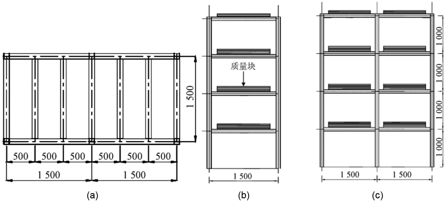
Layout and dimension of test frame (mm): (a) floor plan, (b) side elevation, and (c) elevation.

Installation of mass blocks.
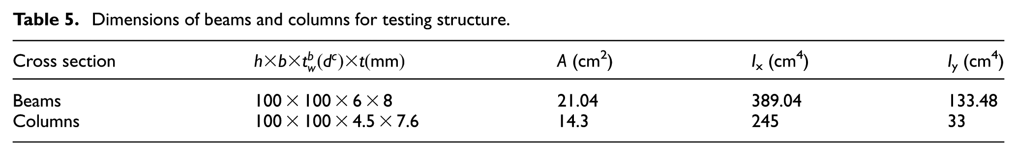
The properties of the beams and columns of the model structure are summarized in Table 5.
Dimensions of beams and columns for testing structure.
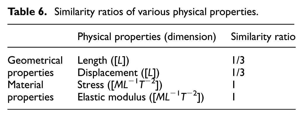
The physical parameters of the experimental model were designed as 1/3 similar theories. The steel frame applied Q235 type of steel that was the same as in the prototype structure. The similitude law of the test steel structure model was designed by the dimensional analysis method. 18 Similar relationships for various physical properties are shown in Table 6.
Similarity ratios of various physical properties.
Design of the VDW
The VDW was designed by the modal strain energy method. The field experimental temperature remained around 23°C (±1°C), and the structural damping ratio was designed to be 15%. In this experiment, the steel frame was assumed to be elastic and the VDW strain was designed 100% at 0.4% story shift. The VDW storage stiffness K′ was 12 kN/cm for damping ratio of 15%. The thickness of the VDW was determined from the maximum damper design strain as 4 mm. The area of the VDW can be determined by A = t K′/2G′, where t is the thickness of each VDW slab and G′ is the storage modulus of NBR. Final dimensions were determined to be 100 mm × 100 mm × 4 mm. Detailed dimensions of the VDW are shown in Figure 7, while Figure 8 shows the bracing connection details.

VDW configuration (mm): (a) dimensions and details of VDW, (b) side elevation of VDW, and (c) front elevation of VDW.

Details of VDW with supporting braces (mm): (a) side elevation, (b) front elevation, and (c) model sketch.
Li and colleagues19–21 newly developed relative displacement and acceleration sensors to identify the damage of shear connectors in composite bridges. To focus on the control effect and response of the VDW, floor accelerations and lateral floor displacements will be mainly measured. As shown in Figure 9, displacement sensors (YHD-50) and accelerometers (CA-YD-1182) were deployed to measure the relative displacement and the accelerations of the steel frame, respectively. The measuring sensors were placed at the center from the first to fourth floors.
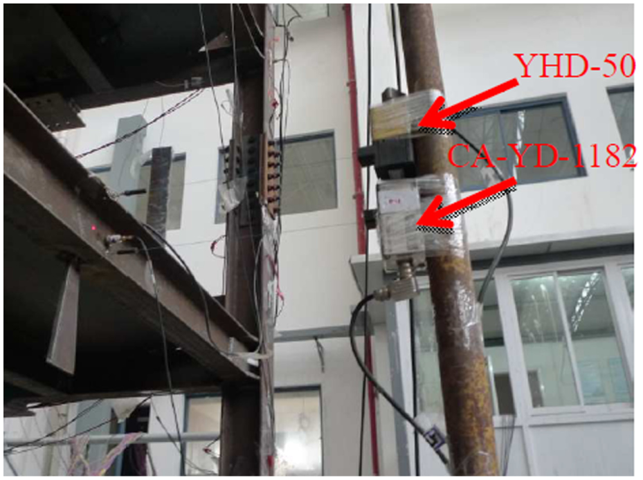
Installation of displacement sensors (YHD-50) and accelerometers (CA-YD-1182).
Experimental results and analysis
Time-scaled El Centro, Taft, 22 and Washington earthquakes with 7 m/s2 acceleration were used as the seismic input for the shaking table test. Detailed information about the earthquakes is shown in Table 7. Figures 10–12 provide the 5% damped acceleration and displacement response spectra for El Centro, Taft, and Washington earthquakes scaled to 7 m/s2, respectively. In the loading process of the uncontrolled frame, the structure exhibited loud frictional sound, large vibration amplitude, and a long static process. In the loading process of the controlled frame, the structure exhibited a short static process.
Detailed information about the El Centro, Taft, and Washington earthquakes.
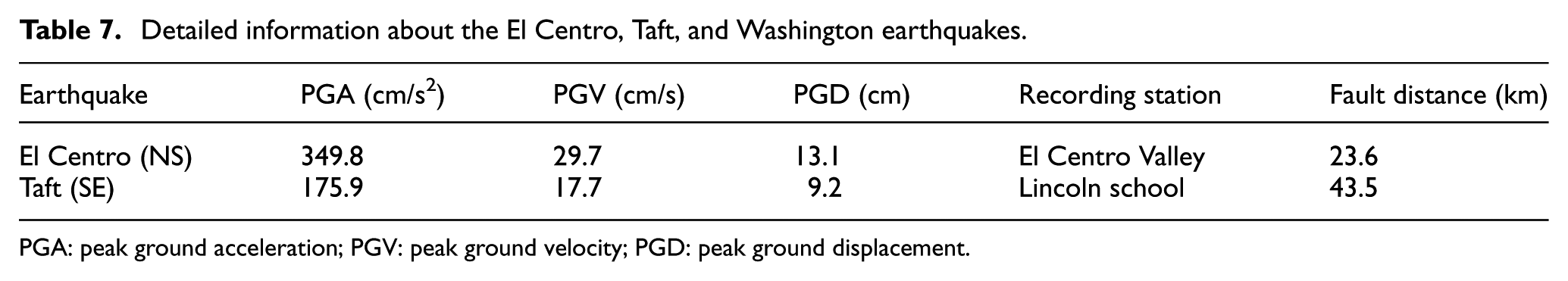
PGA: peak ground acceleration; PGV: peak ground velocity; PGD: peak ground displacement.

Response spectra for El Centro earthquake scaled to 7 m/s2: (a) acceleration response spectra and (b) displacement response spectra.

Response spectra for Taft earthquake scaled to 7 m/s2: (a) acceleration response spectra and (b) displacement response spectra.

Response spectra for Washington earthquake scaled to 7 m/s2: (a) acceleration response spectra and (b) displacement response spectra.
Dynamic characteristics of structure
To identify the dynamic characteristics of the test frame with and without VDW, 0.05 m/s2 white noise excitations were inputted to the shaking table to excite the frame models prior to and after El Centro, Taft, and Washington earthquakes’ input. Table 8 shows the natural frequencies of the frame for different cases. It can be seen that the four frequencies of the controlled structure are 5.00, 14.13, 24.84, and 33.72 Hz. Compared with the uncontrolled structure with frequencies equal to 4.86, 13.59, 24.02, and 36.13 Hz, natural vibration frequencies of all the controlled structures increased due to the fact that the VDW provided supernumerary stiffness.
Structural natural vibration frequencies by white noise scanning.

Structural acceleration response
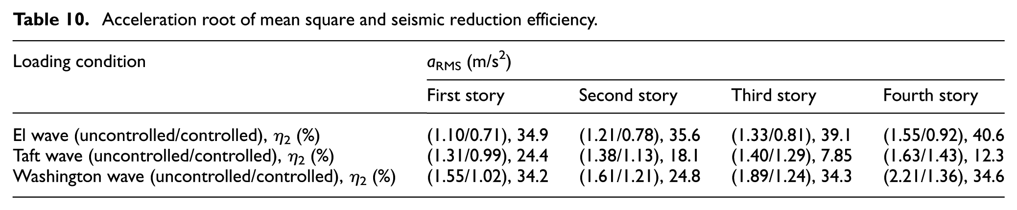
Table 9 provides the maximum acceleration responses and seismic reduction efficiency η1 (η1 is defined as the maximum acceleration difference between the uncontrolled and controlled structures divided by the maximum acceleration of the uncontrolled structure) of three types of earthquake waves under the apg = 7 m/s2 acceleration. Table 10 provides the root mean squares (RMSs) of acceleration responses and seismic reduction efficiency η2 (η2 is defined as the RMS acceleration difference between the uncontrolled and controlled structures divided by the RMS acceleration of the uncontrolled structure) of three types of earthquake waves under the apg = 7 m/s2 acceleration. Figure 13 shows the acceleration time-history response at the first story for the controlled and uncontrolled structures under the condition of apg = 7 m/s2. It can be seen that the VDW provides supernumerary damping for the controlled structure so that the acceleration of each frame story is decreased with a range from 6.61% to 43.9%. The RMS of accelerations significantly decreased with a rate ranging from 7.85% to 40.6%. It can also be indicated that the wall-type brace of VDW is effective in reducing the acceleration responses.
Maximum acceleration responses and seismic reduction efficiency.

Acceleration root of mean square and seismic reduction efficiency.

Acceleration time-history responses: (a) El Centro earthquake, (b) Taft earthquake, and (c) Washington earthquake.
Structural displacement response
Table 11 provides the maximum inter-story displacements from the first to the fourth stories of the frame and the seismic reduction efficiency η3 (η3 is defined as the maximum inter-story displacements difference between the uncontrolled and controlled structures divided by the maximum inter-story displacements of the uncontrolled structure) of three types of earthquake waves under the apg = 7 m/s2 acceleration. Table 12 provides the RMS of acceleration responses and seismic reduction efficiency η4 (η4 is defined as the RMS acceleration difference between the uncontrolled and controlled structures divided by the RMS acceleration of the uncontrolled structure) of three types of earthquake waves under the apg = 7 m/s2 acceleration. Figure 14 shows the displacement time-history response at the midpoint of the first story for the uncontrolled and controlled structures. In general, the structure with VDW has significantly reduced the inter-story displacements compared to that without VDW. Based on the results shown in Tables 9 and 11, the VDW has a better control effect on the midpoint displacement response than on the acceleration response for the first story.
Maximum displacement responses and seismic reduction efficiency.

Displacement root of mean square and seismic reduction efficiency.


Displacement time-history responses: (a) El Centro earthquake, (b) Taft earthquake, and (c) Washington earthquake.
Numerical simulations
To check the accuracy of the analytical model for the steel frame structures with VDW and further verify the analysis method, SAP2000 analysis program for further computation is introduced in this section. Then, the effects of NBR/NSX (70/30) composition are discussed.
Simulations of steel frame with VDW
The element of VDW is simulated by Maxwell element. The layers and thickness of VDW are equal to 2 and 4 mm, respectively. According to equations of ke = (nG′A)/t and ce = (nG″ A)/ωt, the spring stiffness and damping coefficient are determined as 10.5 × 10⁶ N/m and 0.8 N s/m, respectively.
As shown in Figures 15–18, the comparisons of the acceleration time-history response of the first floor of bare frame and the controlled VDW structure under the application of apg = 7 m/s2 El Centro obtained by SAP2000 analysis and experimental are given.
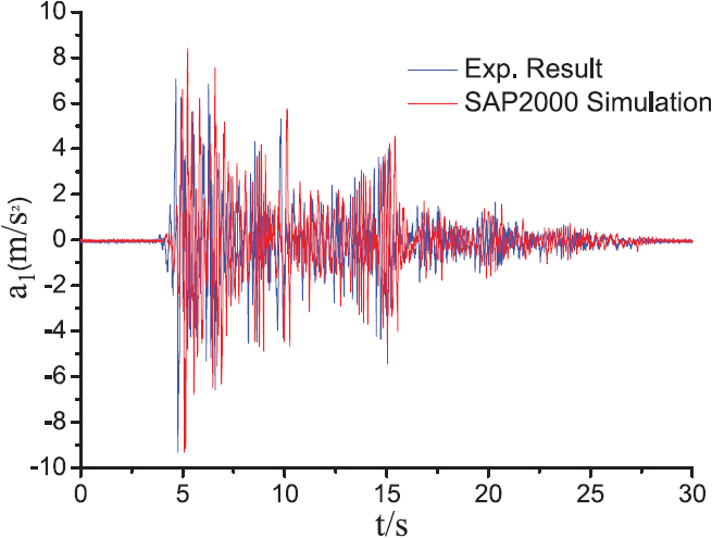
Comparison of acceleration time-history response between test result and simulation result for bare frame.

Comparison of inter-story drift time-history response between test result and simulation result for bare frame.

Comparison of acceleration time-history response between test result and simulation result under controlled type.

Comparison of inter-story drift time-history response between test result and simulation result under controlled type.
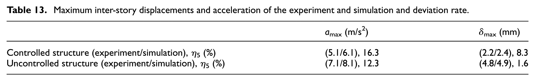
Table 13 provides the maximum inter-story displacements and acceleration of the experiment and simulation and deviation rate η5. The deviation rate η5 is defined as
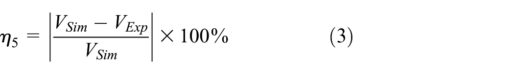
where VExp and VSim denote the values of the experimental and simulated inter-story responses, respectively. It can be seen that the simulated results fit well with the experimental results and the Maxwell model can simulate the characteristic parameters of the VDW changing with excitation frequency and environmental temperature.
Maximum inter-story displacements and acceleration of the experiment and simulation and deviation rate.
Simulations of steel frame with VDW and improved VDW
In order to show the effects of NSX on NBR under earthquake, the improved viscoelastic damping wall (IVDW) made of NBR/NSX (70/30) blends is installed in the steel frame via SAP2000 simulation. The acceleration and inter-story drift response at the first floor are compared to those of the VDW. The layers and thickness of VDW and IVDW are both equal to 2 and 4 mm, respectively. According to equations ke = (nG′ A)/t and ce = (nG″ A)/ωt, the spring stiffness and damping coefficient of VDW and IVDW can be determined, respectively, as shown in Table 14.
Parameters of VDW and IVDW.
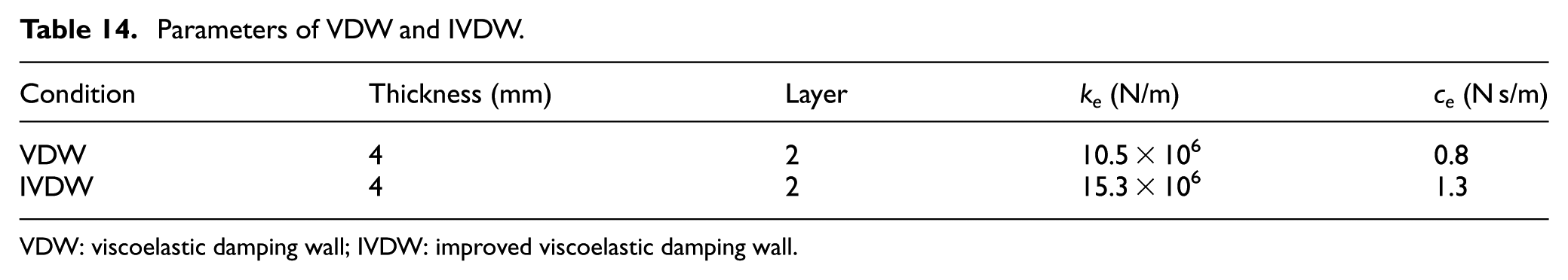
VDW: viscoelastic damping wall; IVDW: improved viscoelastic damping wall.
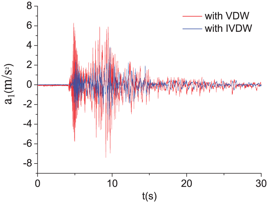
Figures 19–24 depict the comparison chart for VDW and IVDW of the controlled structure under the application of 7 m/s2 El Centro, Taft, and Washington earthquakes. The reduction efficiency η6 (η6 is defined as the maximum difference between the VDW and IVDW divided by the maximum of VDW) can be observed from Table 15. Table 16 shows comparing efficiency η7 (η7 is defined as the RMS difference between the uncontrolled structure and IVDW divided by the RMS of the uncontrolled structure) of IVDW to the uncontrolled case. The reduction efficiency η8 (η8 is defined as the maximum difference between the VDW and IVDW divided by the maximum of VDW) can be observed from Table 17. Table 18 depicts comparing efficiency η9 (η9 is defined as the RMS difference between the uncontrolled structure and IVDW divided by the RMS of the uncontrolled structure) of IVDW to the uncontrolled structure. The simulation results show that under El Centro and Taft earthquakes, the reductions in the peak acceleration and inter-story drift responses by installing IVDW are more significant than by installing VDW. This is because that the NBR/NSX (70/30) blends exhibited higher LA values and storage modulus than those of NBR. Moreover, the reduction range of peak acceleration responses was greater than that of peak inter-story drift responses. These phenomena can be explained by the following reasons. As shown in Table 3, the

Acceleration time-history responses for VDW and IVDW under El Centro earthquake.

Inter-story drift time-history responses for VDW and IVDW under El Centro earthquake.

Acceleration time-history responses for VDW and IVDW under Taft earthquake.

Inter-story drift time-history responses for VDW and IVDW under Taft earthquake.
Acceleration time-history responses for VDW and IVDW under Washington earthquake.

Inter-story drift time-history responses for VDW and IVDW under Washington earthquake.
Acceleration and inter-story drift response maximums (first floor).

VDW: viscoelastic damping wall; IVDW: improved viscoelastic damping wall.
Acceleration and inter-story drift response maximums (first floor).

VDW: viscoelastic damping wall; IVDW: improved viscoelastic damping wall.
Comparing efficiency of IVDW to uncontrolled case (first floor).
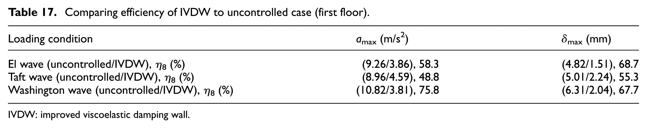
IVDW: improved viscoelastic damping wall.
Acceleration and inter-story drift response maximums (first floor).
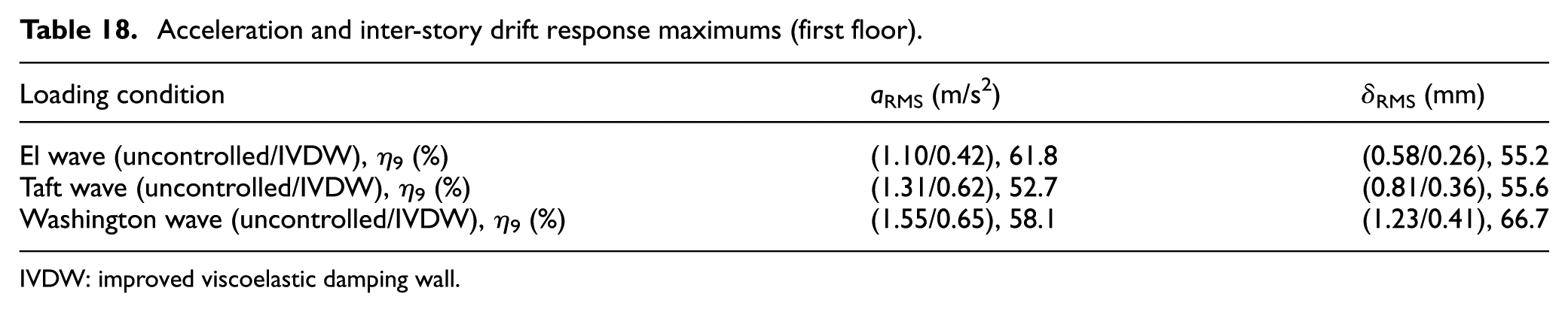
IVDW: improved viscoelastic damping wall.
Conclusion
In this study, NSX fillers with different contents ratios were mixed with NBR. It was found that 30-phr NSX could significantly improve the damping properties of 70-phr NBR to have a larger
To verify the effectiveness of NBR/NSX (70/30) under earthquake, shaking table tests on a four-story steel frame incorporated with VDW were designed and the numerical simulations were performed subjected to apg = 7 m/s2. The results showed that the wall-type brace of VDW was effective in reducing the acceleration and displacement responses of the steel frame. The maximum acceleration of each story of the structure significantly decreased with a rate ranging from 6.61% to 43.9%. From the second to the fourth stories under 7 m/s2 El Centro earthquakes, VDW showed a better effect in displacement response control than in acceleration response control. The SAP2000 simulation results showed good agreement with the experimental results. With IVDW, under El Centro and Taft earthquakes, the reductions in the peak acceleration and inter-story drift responses by installing IVDW were more significant than by installing VDW. Because the improvement level of
Footnotes
Academic Editor: Jun Li
Declaration of conflicting interests
The author(s) declared no potential conflicts of interest with respect to the research, authorship, and/or publication of this article.
Funding
The author(s) disclosed receipt of the following financial support for the research, authorship, and/or publication of this article: The authors are grateful for partial financial support from the National Science Foundation of China (grant nos 51278104 and 51578151) and from the Key Projects of Application Development Plan in Chongqing (project no. cstc2014yykfB30003).