
Abstract
A design for the fail-safe mechanism of a guide vane in a Francis-type hydro turbine is proposed and analyzed. The mechanism that is based on a shear pin as a sacrificial component was designed to remain simple. Unlike the requirements of conventional designs, a shear pin must be able to withstand static and dynamic loads but must fail under a certain overload that could damage a guide vane. An accurate load determination and selection of the shear pin material were demonstrated. The static load for various opening angles of the guide vane were calculated using the computational fluid dynamics Fluent and finite element method Ansys programs. Furthermore, simulations for overload and dynamic load due to the waterhammer phenomenon were also conducted. The results of load calculations were used to select an appropriate shear pin material. Quasi-static shear tests were performed for two shear pins of aluminum alloy Al2024 subjected to different aging treatments (i.e. artificial and natural aging). The test results indicated that the Al2024 treated by natural aging is an appropriate material for a shear pin designed to function as a fail-safe mechanism for the guide vanes of a Francis-type hydro turbine.
Introduction
Fail-safe mechanisms have been designed for various mechanical systems to reduce losses in terms of cost, time, and human life and to reduce environmental damage.1–3 A fail-safe mechanism should be simply implemented in a system and be assured to function properly. In mechanical systems, shear pins are widely used for the fail-safe mechanism. For example, shear pins are installed on gear trains, aircraft mounting engines, 4 valves, 5 couplings, 6 and flocculators. 7 The most challenging problem in analyzing shear pins is the requirement to simultaneously fulfill two constraints in their design. A shear pin must be able to withstand certain operational loads but fail when an overload condition occurs.
The failure of a shear pin is intended to avoid heavy damage to the system caused by operational error. The design requirement of shear pins is unique because it differs from the conventional design requirement to only avoid failure under specific loads. 8 Moreover, the loads imposed on shear pins in a mechanical system depend on the shear pin position. An exact determination of both static and dynamic loadings and proper material selection for shear pins are required. The improper analysis and design of shear pins for fail-safe mechanisms might result in heavy losses.
Failures of a fail-safe mechanism were reported frequently by a hydropower company (GREAT Co., Ltd.) in which the shear pin was not fail during the overload condition. In particular, a guide vane used in a Francis-typed hydro turbine was broken prior to a shear pin failure because of a foreign object entering the water flow. The material used for the shear pin, which is aluminum subjected to artificial aging, is supposed to be unsuitable for protecting the guide vane.
This article aims to design and analyze a fail-safe mechanism using a shear pin for the guide vane. The robust design of a fail-safe mechanism for sustainability of a hydro plant is demonstrated. The guide vane must be reliable for several reasons such as:
The function of the guide vane is vital to controlling water flow before it enters the hydro turbine. 9 Uncontrolled water flow due to malfunction of the guide vane can potentially result in severe damage to other components, such as the turbine and penstock.
Guide vanes are expensive because of their complex shape.
The installation of guide vanes is relatively complicated and time-intensive. 10
Hydro plants usually operate to supply electricity to remote areas, which means their maintenance and repair will be relatively difficult.
In this study, we focus on the load determination for both the guide vane and the shear pin. These analyses can be accurately calculated using commercial engineering software such as computational fluid dynamics (CFD) software and finite element method (FEM) software.4,11,12 We used the CFD Fluent and FEM Ansys programs to calculate the loads corresponding to the opening angles of the guide vane. In addition, the dynamic load imposed on the shear pins by the waterhammer phenomenon was analyzed. Moreover, single-notched shear pins made of aluminum and subjected to different aging treatments, that is, artificial aging and natural aging, were tested to determine the most appropriate material to be used as the shear pin.
Shear pin fail-safe mechanism
A fail-safe mechanism requires a simple and reliable design to ensure that it functions properly. Figure 1(a) shows a schematic of the movement of guide vanes in a Francis-type hydro turbine. Notably, the number of guide vanes depends on the hydro turbine size. In this study, 16 guide vanes used for a mini-scale turbine were analyzed. The guide vanes are numbered from 1 to 16 in counterclockwise order. The guide vanes rotate under torque, which is controlled by hydraulic pressure on the system.

(a) Schematic fail-safe mechanism for guide vanes using hydraulic as driving force and (b) shear pin dimension with unit of mm.
A shear pin was installed in the arm rod of each guide vane. The shear pin was designed as a sacrificial component that would break under heavy load. The broken shear pin will release load transfer, hence avoiding damage to the guide vane. This mechanism can reduce the cost and time required for repair because a shear pin is relatively cheaper than a guide vane. Moreover, the installation of a new shear pin to replace the broken one does not require overall disassembly of the hydro turbine. Figure 1(b) shows the dimension of the shear pin. Note that necking diameter of the shear pin has small tolerance, which indicates that it should be carefully manufactured.
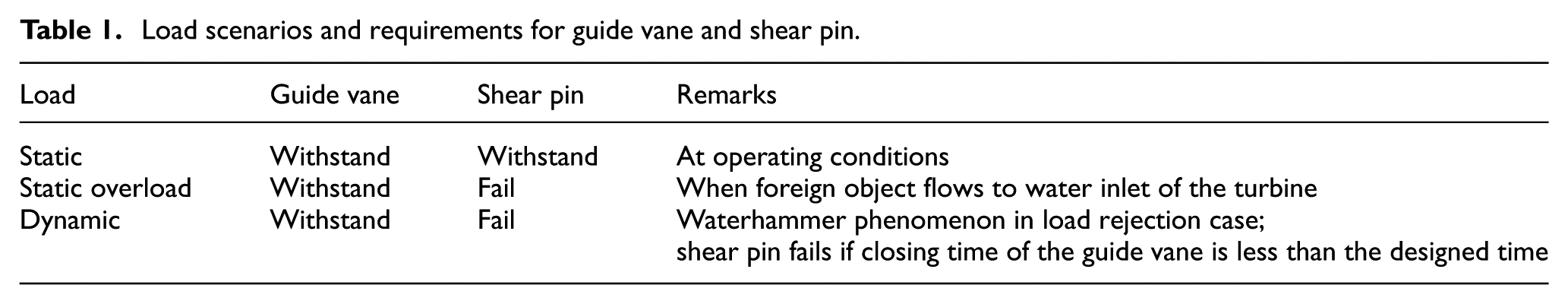
The following three categories of loads influencing both the guide vane and the shear pin were investigated: the static operating load, static overload, and dynamic load. A static operating load occurs when the turbine is generating electricity under specific conditions. The load originates from water pressure imposed onto the guide vanes. A static overload occurs when a foreign object impedes the rotational movement of the guide vane. It might occur as a consequence of a problem or failure in the filtration system of the water inlet. A dynamic load occurs because of waterhammer. Generally, waterhammer occurs when the fluid flowing through the penstock is forced to suddenly stop or change direction. 13 Specifically, it occurs when the guide vanes close as soon as possible to avoid a sudden increase in the rotation speed of the hydro turbine due to disconnection of electric power. 14 The guide vane must be able to withstand all three load scenarios, whereas a shear pin must withstand static operational load but fail under static overload or dynamic load. The details of the load scenarios and requirements for guide vanes and shear pins are shown in Table 1. Investigation of the various loads imposed onto guide vanes is the main consideration in the design of their fail-safe mechanism.
Load scenarios and requirements for guide vane and shear pin.
Load analysis of guide vanes
Static load case
A guide vane and shear pin must endure their opening angle when the turbine is in operation and producing electric power. We modeled the case of static operating load using the Fluent-CFD software. This modeling was intended to determine the static torques that act on the guide vanes at various opening angles. With guide vane no. 1 used as reference for the opening angle, guide vanes were analyzed at opening angles of 15°, 30°, 45°, 60°, and 75° with respect to the horizontal line (x-axis). Notably, an angle of 15° means the guide vanes are fully opened, whereas an angle of 75° means the guide vanes are totally closed.
The k-epsilon standard flow model of the Fluent-CFD software was selected on the basis of its advantages. This model describes the full flow of fluid but with a relatively short computation time. In addition, the k-epsilon model is also suitable for field conditions of water flow.15,16 A two-dimensional model of chasing turbine, static vane, and guide vane was created for a steady-state condition. Moreover, a segregated implicit solver was selected. The segregated implicit solver calculates the Reynolds-averaged Navier–Stokes (RANS) equations in stages and solves the equations separately. 17
Figure 2 shows a typical result of the CFD Fluent model describing the pressure contour acting in a chasing turbine for a guide vane in the case of an opening angle of 30°. A water discharging rate of 2.3 m3 s−1 was applied in the water inlet with a pipe of 0.8-m diameter. The largest torque due to pressure and the friction force of the water was received by guide vane no. 13 of the turbine at an opening angle of 30°. A maximum torque of 649.9 N m in a clockwise direction was observed. These results were obtained because guide vane no. 13 is positioned in front of the water inlet and is therefore directly facing high water pressure. The details of the torque in each guide vane are shown in Figure 3. A negative sign of torque indicates torque applied in the clockwise direction. All guide vanes and shear pins must be able to withstand these torques.

Pressure contour acting in the chasing turbine. An opening angle of guide vanes is 30°.

Torque acting in guide vanes for several opening angles of guide vanes.
Static overload case
For static overload analysis, a foreign object, such as a stone or a wooden rod, is considered to flow into the water inlet and inhibit the movement of the guide vane. The presence of this object prevents the guide vane from completely closing. However, the guide vane is nonetheless continuously forced to close. The resulting static overload could result in failure and possibly permanent deformation of the guide vane. The shear pin is designed to fail to release the load before the guide vane fails.
The static overload model was conducted using the FEM Ansys program integrated into the Autodesk Inventor 2010 CAD software. The base material of the guide vane is martensitic stainless steel with a yield strength (σ yield ) of 551 MPa. Fixed and pinned constraints were applied for certain guide vane surfaces. A pressure of 0.46 MPa, which is equivalent to the water pressure under operating conditions, was also applied to the guide vane. A foreign object was represented by an incident load imposing the guide vane edge. This edge is in farthest position to rotation axis of the guide vane. The edge position was selected in order to generate a highest torque with minimum incident load, which is a worst case of static overload analysis.
Figure 4 shows the FEM modeling result for static overload case. The guide vane was fail indicated by safety factor of 1 when the incident load of 12 kN was applied. The von Mises failure criterion was employed in the analysis. The guide vane failure was predicted to occur in the top of the guide of the vane shaft. The maximum torque imposed by the guide vane of 1135.37 N m in a clockwise direction was recorded on the FEM modeling result.

Guide vane modeling for overload case.
Dynamic load case
The waterhammer phenomenon causes the water flow pressure to abruptly change. 18 The resulting high pressure can initiate the failure of both the guide vane and the penstock. In the electrical load rejection case, the waterhammer effect can be reduced by extending the closing time of the guide vane which will reduce water-flow-speed alteration in the penstock. The relationship between the pressure alteration and water-flow-speed alteration can be expressed as a differential equation proposed by Joukowsky (see Ghidaoui et al. 19 , Eq. 1) as follows

where p is the water pressure, C is the water flow speed during opening or closing of the guide vane, and a is the speed of pressure waves that move along the penstock. The speed of the pressure waves is calculated using equation (2)
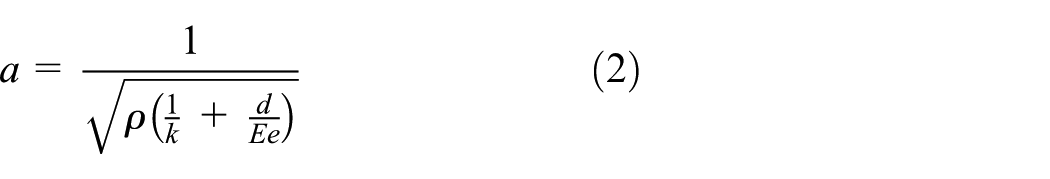
where k is the bulk modulus of water, E is the modulus of elasticity of the pipe, d is the pipe inner diameter, e is the pipe thickness, and ρ is the specific mass of the water. Note that the longer closing time can cause an uncontrollable increase in the speed and unbalance the rotor turbine. The appropriate closing time should be selected with consideration of these constraints.
The maximum head of the turbine during a certain closing time can also be obtained from the Allievi graphs with appropriate nondimensional parameters. 19 The parameters are γ, Z, and θ, which are expressed as shown in equations (3)–(5), respectively
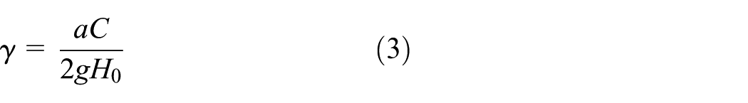
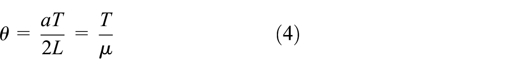

where g is gravitational acceleration, H0 is the initial head, L is the pipe length, T is the closure time, µ is the critical time, and Hmax is the maximum head.
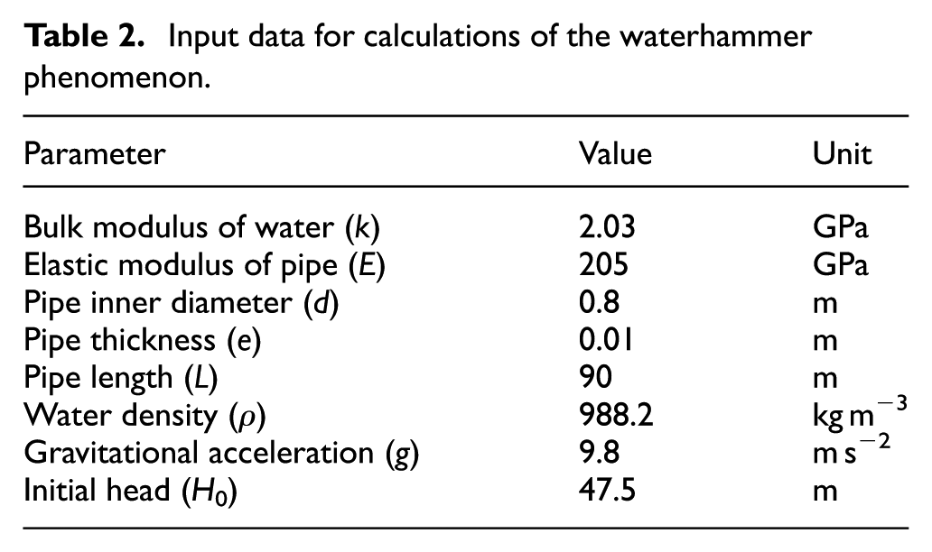
Table 2 shows the parameters required for calculation of the waterhammer phenomenon, as obtained from GREAT Co., Ltd. Figure 5 shows the curves of head rise corresponding to closing time. Notably, a short closing time of the guide vane leads to a high head rise, which means high pressure occurs. The closing time must be carefully selected to avoid operational error that could damage both the penstock and the guide vane.
Input data for calculations of the waterhammer phenomenon.

Head alteration versus closing time of the guide vane.
Penstock pressure increases during the closing process of the guide vane. A rapid alteration of the pressure and a high maximum pressure can cause a dynamic loading, which might result in failures in the penstock and the guide vane. The type of the load can be determined through analysis of its strain rate. 20 The strain rate can be calculated using equation (6)
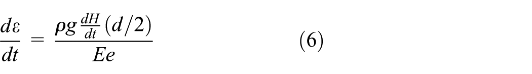
where dH/dt is the rate of head alteration. Equation (7) is used to determine the safety factor based on von Mises theory, where σt, σa, and σr are the principle stresses for the penstock. The results from the calculations of the waterhammer effect on the penstock are shown in Table 3

Notably, a low strain rate occurred in the penstock for each designed closing time, even though the dynamic load from the waterhammer effect was imposed. The low strain rate indicates that a quasi-static analysis is sufficient. Moreover, the safety factor of the penstock is relatively high. We used the CFD Fluent software to calculate the torque of guide vane during the closing time. Dynamic head values of five opening angles, that is, 15°, 30°, 45°, 60°, and 75° were used as input data to determine the torque of the guide vane. The closing process of the guide vane was assumed to occur at a constant speed. Figure 6 shows the results of the modeling for guide vane no. 13 which imposes highest torque.
The results of calculations of the strain rate and safety factor based on von Mises criteria.


Torque in a guide vane no. 13 for several closing times.
Material selection of shear pin
The concept of a fail-safe mechanism is to sacrifice the shear pin to save the guide vane in the event of unexpected conditions. The static load scenarios for shear pin failure are described in Table 1. To satisfy the requirements, the boundaries of an allowable ultimate shear strength of the shear pin (τu) should be properly investigated. The boundaries consist of a lower limit and an upper limit of τu. The lower limit of τu was obtained by calculating the static operating load case. The shear pin must be able to withstand the shear stress due to load transfer from the guide vane under a static operating load. By contrast, the shear pin must fail before the shear stress exceeds the upper limit of τu. The upper limit of τu was obtained from calculations of the static overload case when the guide vane begins to fail or plastically deform.
Upper and lower limits of τu for a static load
A free body diagram of the shear pin and guide vane is shown in Figure 7. Shear stress in the shear pin was transferred from the guide-vane torque. The shear stress was simply calculated using equation (8)

where Fs is shear force, A is the cross-sectional area of the shear pin, R is the length between the center of the guide vane and the center of the shear pin (90 mm), α is the force angle, and r is the designed shear-pin radius. The force angle α changes according to the opening or closing position angle of the guide vane. A force angle of 0° was used to obtain maximum shear stress in the shear pin in the shear stress calculations.

Free body diagram of a guide vane and shear pin.
On the basis of the guide vane torque results from the static operating load case, we calculated the shear stress in the shear pins using equation (6). The calculation results are plotted in Figure 8. Guide vane no. 13, which is subjected to a maximum torque of 647.9 N m in the clockwise direction (Figure 3), exhibits the highest shear stress in its shear pin (143.22 MPa). Therefore, this shear stress value becomes the lower limit of τu. It is reasonable because the guide vane and its shear pin were directly exposed by water inlet which causes highest water pressure. The upper limit of τu was determined in the same manner as the lower limit of τu using the maximum torque from the static overload case of 1135.37 N m (in the clockwise direction). Hence, the upper limit τu is 250.97 MPa. On the basis of these results, the allowable τu due to the static loading is defined as the dark area in Figure 8.
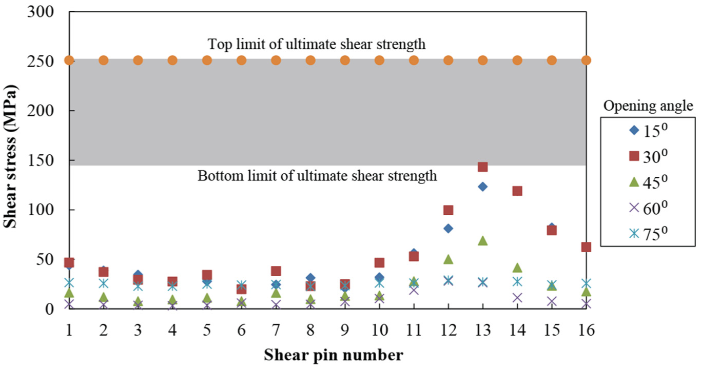
Allowable τu due to static load.
Designed closing time of guide vane
On the basis of the guide vane torque results from the dynamic load case, we again calculated the shear stresses in the shear pins using equation (8). We then determined a new allowable τu by combining the analysis results for static operating load, overload, and dynamic loads due to the waterhammer effect. The dynamic load analysis only focuses on the shear pin no. 13 because it imposes the highest shear stress during normal operation. Figure 9 shows the waterhammer-induced changes in shear stress on the shear pin no. 13 for various closing times. Notably, shear stress in the shear pin increases dramatically when the closing time of the guide vane is 2 s. By contrast, for closing times of 4, 7, and 10 s, the shear stress changes only slightly.

The allowable τu after combining three different load cases.
The increase in speed of the turbine rotor and the pressure rise in the penstock are the two constraints that should be considered in determining the closing time of a guide vane in the electric power rejection case. To avoid an increase in speed, the closing time of the guide vane must be short. In this case, 2 s of closing time is considered as the suitable option. Unfortunately, the short closing time will cause small band of shear stress, which means the shear pin should be selected very strictly. A slower closing time is also required to prevent the pressure rise. In this case, 10 s of closing time appears to be more appropriate.
After careful consideration of the aspects of both speed and pressure increases, 4 s of closing time was determined to be the best closing time that balances the increases in both turbine speed and penstock pressure. The lower limit of τu is changed to 165.07 MPa and is indicated by a dashed line in Figure 9. Thus, to save the guide vane, the shear pin will fail if the closing time is less than 4 s, as specified in Table 1. Note that on the short closing time case, only shear pin no. 13 fails and causes guide vane no. 13 to lose its control and leave water flow to the turbine. It reduces the pressure rise but the turbine speed will not be out of control because the water flow is considerably small, which is 1/16 of total water flow.
Experimental validation
We conducted an experimental study to determine the suitable shear pin material for use as the sacrificial component. The shear pin must have a τu in the range of the allowable τu values. A simple direct shear test was designed to conduct the validation test using a tensile testing machine equipped with a special shear-test fixture.
Two types of specimens were subjected to different aging treatments and subsequently tested: aluminum alloy Al2024 with artificial aging (heated at 210°C for 5 h) and aluminum alloy Al2024 with natural aging (left at room temperature). Three samples were tested for each type of specimen to observe the statistical variation and consistency of the test procedure. The results of shear strength tests are shown in Figure 10. On the basis of the experimental tests, Al2024 with natural aging treatment is suitable for use as shear pins because it exhibits an average shear strength of 186 MPa, which is slightly higher than the lower τu of 165 MPa. The τu of the artificially aged Al2024 approaches the τu upper limit, which possibly cause the breakage of guide vane during overload condition.

Shear strengths of Al2024 shear pins subjected to artificial aging and natural aging treatments.
Conclusion
A design of the fail-safe mechanism for a guide vane of a hydro turbine was studied and analyzed under various loading scenarios. The loading calculations for the guide vane and shear pin were conducted using finite element software (CFD Fluent and FEM Ansys) to assure accuracy of the shear pin material selection. According to calculations for static load and overload conditions, the allowable τu values are between 143.22 and 250.97 MPa. In the case of a dynamic load from the waterhammer phenomenon, the lower limit of the allowable τu increases slightly to 165.07 MPa. This condition occurs when the closing time of the guide vane is 4 s. Validation experiments indicated that Al2024 subjected to a natural aging treatment is a suitable shear pin material, with an average τu of 186 MPa. This study focused on a mini-scale Francis-type hydro turbine with 16 guide vanes. However, an identical procedure for the design and analysis of the fail-safe mechanism could be applied to a Francis-type hydro turbine of any scale. In addition, a grading design method for shear pin as a sacrificed material of fail-safe mechanism might be interesting as a future work.
Footnotes
Acknowledgements
The authors would like to thank GREAT Co., Ltd., a hydro turbine company, for providing the shear pin material, technical design, and valuable discussions.
Academic Editor: Shun-Peng Zhu
Declaration of conflicting interests
The author(s) declared no potential conflicts of interest with respect to the research, authorship, and/or publication of this article.
Funding
The author(s) received no financial support for the research, authorship, and/or publication of this article.