
Abstract
A rotating actuator in the active mass damper system for structural vibration control is proposed in this article. Different from the linear actuator in the traditional active mass damper system, a rotating actuator is developed to suppress structural vibration. With the introduction of rotational movement and external excitations, nonlinearity and uncertainty are considered in the system. Using the Lagrange equations, the mathematical model of the nonlinear structure–active mass damper system with uncertainty is derived. Regarding the uncertainty in the model, a hierarchical sliding mode controller is designed based on Lyapunov stability theory. Numerical and experimental analyses are conducted to prove the effectiveness of the control algorithm and the reliability of the control device.
Keywords
Introduction
Active mass damper (AMD) control system has been widely studied in the structural vibration control of civil structures.1–3 The system owns more potential than tuned mass damper (TMD) systems because of its superior effectiveness and larger spectral bandwidth.4,5 The first active control experiment was conducted by Aizawa et al. 6 in 1987, in which AMD was installed on the top floor of a four-story structure. In 1988, the 1:4 bench-scale experiment of six-story structure was completed in the American National Earthquake Engineering Research Center by Soong et al. 7 Ou and colleagues8,9 studied the feasibility of application of AMD systems on the offshore platforms, and the active control of ice-induced vibration was studied on the 1:10 bench-scale structure. Additionally, control designs considering the nonlinearity of structures have been invested.10,11 Stewart and Lackner 12 studied the effect of interaction between the actuator and target structure. Control algorithms used in AMD system for structural vibration control are mostly developed based on the modern control theory, which are appropriately modified according to the properties of civil structures. The frequently used methods include linear quadratic regulator (LQR), 13 independent modal optimal control, 14 pole assignment control, 15 optimal pulse control, 16 and H2 and H∞ norm optimal control.17,18
In the traditional AMD system for structural vibration control, hydraulic system and motor servo system are mostly adopted as actuators. However, there exist some problems which are difficult to solve in these systems. For hydraulic system, the problems are structural complexity, expensive maintenance, large space occupation and low efficiency of energy utilization. In motor servo system, motor torque is transferred to the structure through mechanical parts, like ball screws. As a result, extra inertia and friction of mechanical contact slow down the response of the control system, which affects the control efficiency. For the purpose of enhancing the performance of actuators, some researches have been conducted such as the design of swing-style AMD 19 and the introduction of electromagnetic devices with semi-active control property. 20 Moreover, Zhang and colleagues4,21 proposed a kind of electromagnetic mass damper system, which can impose electromagnetic force on the structure directly to make the mechanical contact unnecessary. Nevertheless, such devices may not work well when they reach maximum extension of their stroke. Exceeding physical limits of the actuators may trigger nonlinearity consequentially 22 and impair the control performance of the system or even lead to device damage. Therefore, limited stroke should be considered in designing controllers for AMD system. Venanzi et al. 23 proposed the enhanced skyhook algorithm approach for AMD system by modulating the control force based on a nonlinear smooth function of the ratio between actuator’s force and saturation limit. They also put forward a nonlinear control strategy, in which the control force is given by the sum of a linear function of the state of the system and a nonlinear dissipative force that becomes effective in the proximity of the physical limit of the actuator. 24 Besides, a general approach was proposed by Materazzi and Ubertini 25 based on the tool of the state-dependent Riccati equation, in which physical limitations are considered. To sum up, limited mass stroke make the controller designing for AMD system complicated.
To solve the problem of limited mass stroke of AMD system, a rotating actuator for AMD system is proposed in this article. Instead of rectilinear motion in the traditional AMD, inertial mass with rotational movement is driven by a rotating actuator. Regarding this device, no physical limitations are needed to impose on the inertial mass. The outline of the rest of article is as follows. First, the mathematical model of the proposed system is derived. Second, based on the model, the hierarchical sliding mode controller is designed and the stability of the control system is analyzed. Finally, the numerical and experimental results are presented and studied.
Mathematical model
Structure–AMD system with rotating actuator is shown in Figure 1, which consists of a one-floor structure and an AMD with rotating actuator on the top. The structure has mass M, stiffness coefficient K, and damping coefficient C. The rotating mass is m, which is driven by the motor torque N. The rotating radius is R, and the rotating angle is θ. The moment of inertia of the mass with respect to its barycenter is J. The structure has linear motion in the horizontal direction, and its displacement is x. The displacement of the structure in the vertical direction is not taken into consideration in this article because it is negligible with respect to x.
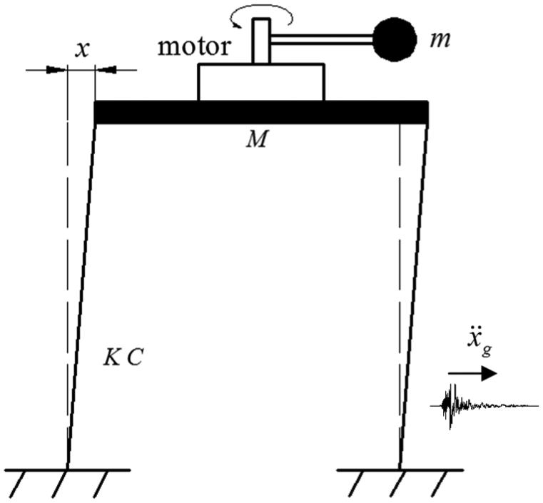
Structure–AMD system with rotating actuator.
The Lagrange equations are adopted to derive the model of the entire system. The Lagrange equations can be expressed as

where L is the Lagrangian of system of particles, qn are generalized coordinates, n is the degree of freedom, and Qn are generalized forces. According to the Lagrange equations, the dynamics of the whole system should be

where
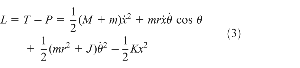
where T and P are the kinetic energy and potential energy of the system, respectively. By substituting the Lagrangian into equation (2), the dynamics of the whole system can be obtained as follows

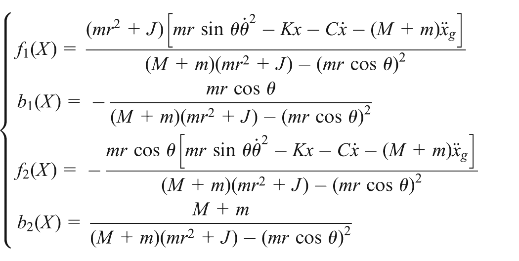
For the convenience of controller design, the dynamical model with uncertainty can be rewritten as follows
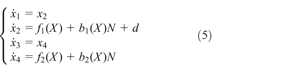
where
Hierarchical sliding mode controller
The frequently used linear control methods such as LQR and linear quadratic Gaussian (LQG) for active control of the civil structures are not suitable for the structure–AMD system with the rotating actuator because of the existence of nonlinearity and uncertainty in equation (5). Thus, the sliding mode control algorithm is adopted to design the controller because of its robustness to suppress the uncertainty of disturbance. The system has more independent state variables (x and θ) than control input (N), which makes it an underactuated system. To solve the problem of underactuation, a hierarchical sliding mode control (HSMC) method is adopted to design the controller. 26
Two groups of state variables (x1, x2) and (x3, x4) can be treated as two subsystems of the entire system. For the two subsystems, a pair of sliding surfaces are constructed as the first-level surfaces

where c1 and c2 are positive constants. Apparently, if the two groups of state variables can reach the first-level surfaces, x and θ will approach zero exponentially.
Using the equivalent control method, when the system is on the first-level surfaces, the equivalent control law of the subsystems can be obtained as

To ensure that each subsystem follows its own sliding surface, the total control law must include some portion of the equivalent control law of each subsystem. The total control is defined as follows

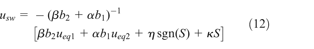
where usw is the switch control part of sliding controller. Then, the second-level sliding surface is constructed as follows

where α and β are positive constants. The switch control can be derived using Lyapunov stability theory. The Lyapunov energy function of structure–AMD system can be selected as

Differentiating V(t) with respect to time gives

Let

It can be obtained
Thus, equation (11) can be rewritten as

Therefore, the second-level sliding surface is stable and the final control input is
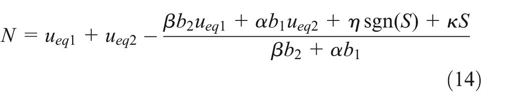
The stability of both the first and second sliding surfaces has been proved by Wang et al. 26 The existence of sign function in equation (14) will cause chattering phenomenon in the control input N. To decrease the adverse effect of chattering on control effectiveness, the boundary layer method is introduced to eliminate the chattering in N. This method is to replace the sign function sgn(S) in equation (14) with sat(S), which is a linear function with saturation
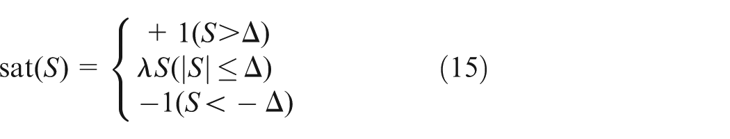
where Δ and λ are positive constants. In this way, the control input N becomes continuous when S varies within the range of (−Δ, Δ). Replacing sgn(S) with sat(S) in equation (14), the control input N with chattering elimination can be obtained.
Numerical and experimental analyses
In order to verify the effectiveness of the AMD system with the rotating actuator for structural vibration control, the experimental platform is constructed as shown in Figure 2. dSPACE (RS1104) system is used for the control system. The control torque N is provided by the Maxon EC flat motor, and Nemicon OVW2-1024-2MD encoder is adopted to measure the rotating angle of the rotating mass. The displacement of the target structure is measured with the laser displacement sensor.

Experimental platform of structure–AMD system with rotating actuator: (a) target structure and the AMD with rotating actuator and (b) dSPACE control board and motor driver circuit.
Parameter identification
It is necessary to identify the parameters of the target structure before carrying out the control tests with AMD. The parameters like structure mass, rotational inertia mass, and radius of rotation can be obtained easily without parameter estimation. The stiffness coefficient and damping coefficient of the structure need to be identified.
The displacement-based sinusoidal sweep excitation on the target structure is used to get the fundamental frequency. The excitation amplitude is 1 cm, the frequency range is 2–12 Hz, and the linear sweep speed is 0.4 Hz/s. The excitation is applied by a shaking table. Figure 3(a) shows the time history of displacement. The fundamental frequency of the structure can be found through frequency spectral analysis. As shown in Figure 3(b), the fundamental frequency f = 0.8545 Hz, and the corresponding circular frequency ωD = 2πf = 5.3689 rad/s.

Experimental results with sinusoidal sweep excitation: (a) displacement response with sweep excitation and (b) frequency spectral analysis.
Free vibration test is conducted to compute the damping ratio of the structure, and the result of free vibration test is shown in Figure 4.

Time history of displacement in free vibration test.
Processing the data in Figure 4 with the following formula

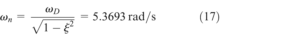
The damping ratio is calculated as 0.0117. Ai/Ai+1 are the ratios of successive maximum peaks. Therefore, the undamped vibration frequency is
The stiffness coefficient is

and the damping coefficient is

Through parameter identification, we can get the parameters of the structure, which are presented in Table 1.
Structural parameters of the experimental model.

Numerical analysis
The numerical simulations are conducted by MATLAB/Simulink software to validate the effectiveness of AMD with the rotating actuator. The control effect of AMD is analyzed with the simulation results as shown in Table 2. Different excitations including initial displacement and earthquake excitation are both considered.
Numerical analysis: peak and RMS values of structural displacement.

AMD: active mass damper; RMS: root-mean-square.
The control effect is defined as
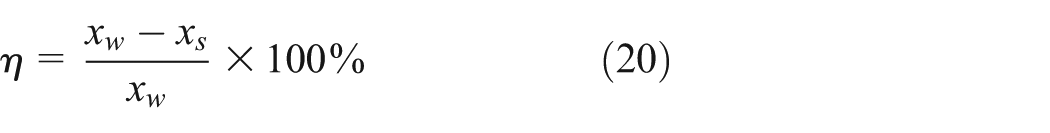
where xw and xs are the structural displacements without and with control, respectively.
The response of the structure under initial displacement is discussed first. The parameters of HSMC controller are obtained through parameter optimization, which are a1 = 1/150, a2 = 30, α = 15, β = 1/10, η = κ = 5, Δ = 10, and γ = 10 is the upper bound of d. The corresponding simulation results are shown in Figure 5.
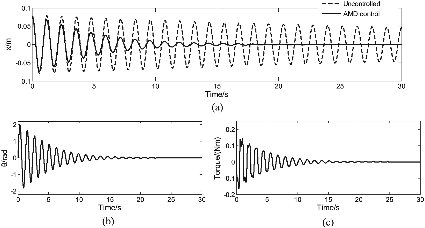
Simulation results of AMD–structure with initial conditions
For comparison, Figure 5(a) shows different responses of the structural displacement in uncontrolled case and AMD control case. The decaying of the structural displacement is faster with AMD control force applied to the system than the case without control. For quantitatively analyzing, the criterion ts is introduced to denote the time consumed to bring down the structural displacement to 10% of its initial value. Specifically, ts is 156 s in the uncontrolled case, while it is 11 s under AMD control. Furthermore, the control effect ηRMS is 61% with respect to the root-mean-square (RMS) value of displacement. Besides the structural displacement, the rotating angle of inertia mass can be stabilized at the equilibrium point.
Second, the simulation of the AMD with the rotating actuator is conducted to suppress the earthquake-induced vibration. El Centro earthquake wave is adopted as the earthquake excitation in the simulation. The earthquake time history is shown in Figure 6. In the following experimental part, the earthquake excitation is generated by the shaking table when experimental tests are carried out.

Time history of El Centro earthquake wave.
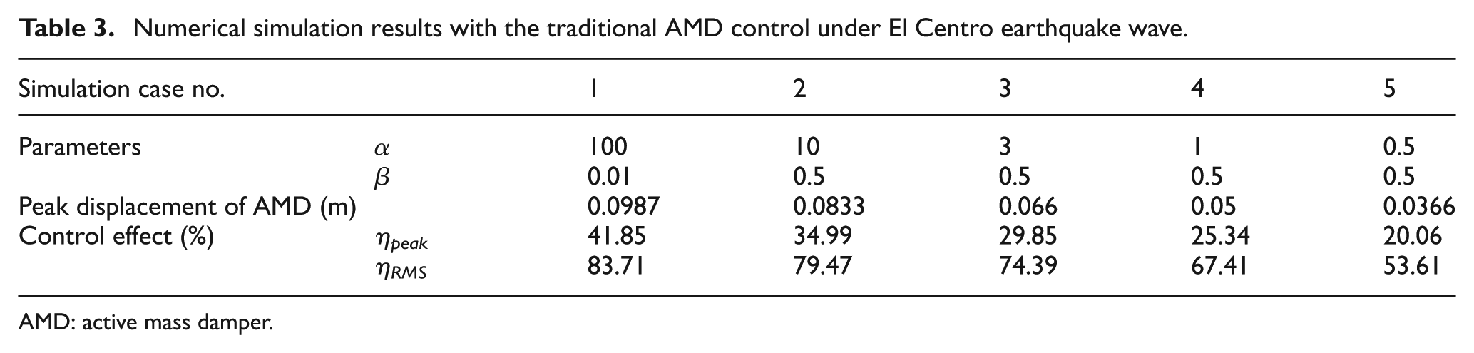
As shown in Figure 7, earthquake-induced vibration is suppressed when AMD control force is applied to the structure. By quantitatively analysis, the control effect ηpeak is 23.54% with respect to the peak value of dispacement, and ηRMS is 71.1% with respect to RMS value. It can be observed that AMD with the rotating actuator is effective to control the structural vibration under earthquake excitation. In order to compare with the traditional AMD control system based on the translational motion, numerical study is conducted on the same structure used in this article. LQR is adopted to control the actuator. The numerical simulation results are shown in Table 3. The control parameters Q and R are determined as

where M and K are the structural mass and stiffness coefficient, respectively, and I is the unit matrix.
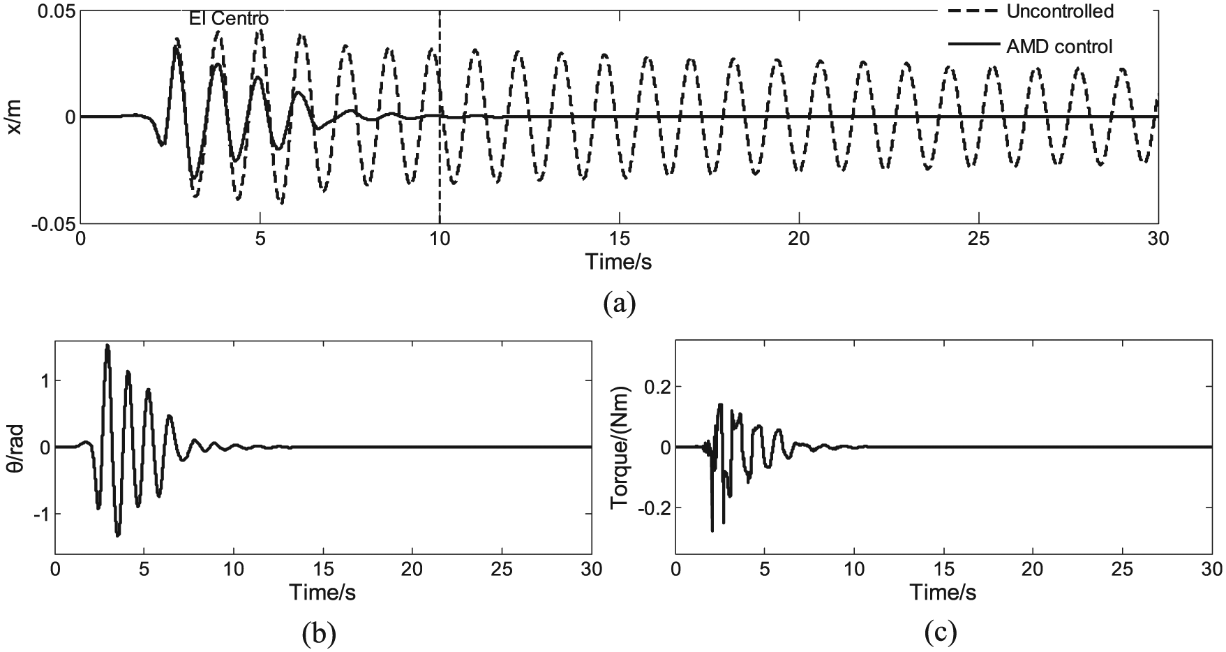
Simulation results of AMD–structure under El Centro earthquake wave: (a) structural displacement response, (b) angle of rotating mass under AMD control, and (c) control torque.
Numerical simulation results with the traditional AMD control under El Centro earthquake wave.
AMD: active mass damper.
From these results, it can be observed that the traditional AMD control can achieve better control effect than the proposed control device. However, when the peak displacement of the traditional AMD system decreases, the control effect will also decrease and become even worse than the proposed control device. This is also one of the advantages of the proposed device which has circular movement to solve the problem of limited mass stroke of the traditional AMD system. Therefore, in the case of limit space for the motion of AMD, the proposed device will obtain better control effect.
Experimental analysis
Control tests of structure–AMD system with initial displacement and earthquake excitation are conducted on the experimental platform. The peak and RMS value of structural displacement are shown in Table 4. Figures 8 and 9 show the corresponding experimental results under two different cases.
Experimental analysis: peak and RMS values of structural displacement.
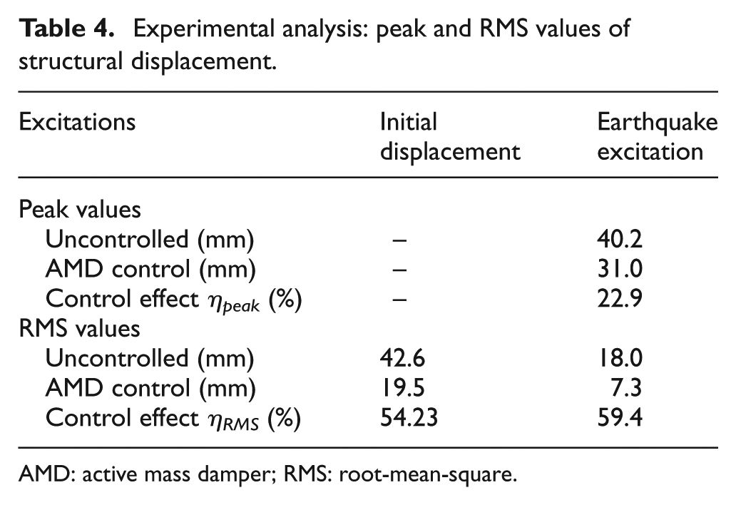
AMD: active mass damper; RMS: root-mean-square.
Experimental results of AMD–structure with initial conditions

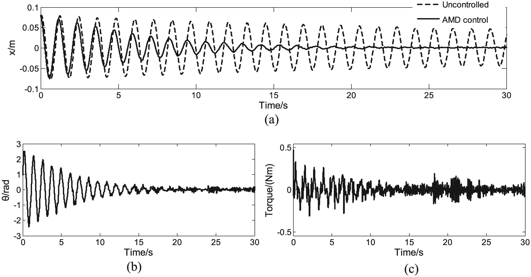
Experimental results of AMD–structure under El Centro earthquake wave: (a) structural displacement response, (b) angle of rotating mass under AMD control, and (c) control torque.
Figure 8(a) shows the comparison results of structural response between the uncontrolled case and AMD control case. In the uncontrolled case, it takes 140 s to bring the structural displacement down to 10% of the initial value. In contrast, it only takes 14 s when the control force is applied on the structure. Regarding the RMS of displacement, the control effect is 54.23%.
Figure 9(a) shows the structural response under earthquake excitation. The El Centro earthquake wave is considered as earthquake excitation in these tests, whose time history is shown in Figure 6. More specifically, the peak reduction and RMS reduction in the displacement are ηpeak = 22.9% and ηRMS = 59.4%, respectively, with AMD control. Through the comparison between different cases, it concludes that the AMD system with the rotating actuator is effective to suppress structural vibration under different excitations.
Conclusion
A rotating actuator in AMD system for structural vibration control is proposed in this article. Its modeling and controller design are discussed. The numerical and experimental results validate the effectiveness of the proposed AMD system to suppress the structural vibration considering uncertainty and nonlinearity. Moreover, the inertial mass driven by rotating actuator has circular movement which solves the problem of limited mass stroke. However, because of the complex vibration properties of civil structures, the rotating actuator has not been studied sufficiently. The application of AMD with rotating actuator in structural vibration control needs further research.
Footnotes
Academic Editor: Nasim Ullah
Declaration of conflicting interests
The author(s) declared no potential conflicts of interest with respect to the research, authorship, and/or publication of this article.
Funding
The author(s) disclosed receipt of the following financial support for the research, authorship, and/or publication of this article: This work was supported, in part, by the National Science Foundation of China under Award No. 51378093 and No. 91315301.