
Abstract
In the spline rolling process with round dies, additional kinematic compensation is an essential mechanism for improving the division of teeth and pitch accuracy as well as surface quality. The motion characteristic between the die and workpiece under varied center distance in the spline rolling process was investigated. Mathematical models of the instantaneous center of rotation, transmission ratio, and centrodes in the rolling process were established. The models were used to analyze the rolling process of the involute spline with circular dedendum, and the results indicated that (1) with the reduction in the center distance, the instantaneous center moves toward workpiece, and the transmission ratio increases at first and then decreases; (2) the variations in the instantaneous center and transmission ratio are discontinuous, presenting an interruption when the involute flank begins to be formed; (3) the change in transmission ratio at the forming stage of the workpiece with the involute flank can be negligible; and (4) the centrode of the workpiece is an Archimedes line whose polar radius reduces, and the centrode of the rolling die is similar to Archimedes line when the workpiece is with the involute flank.
Keywords
Introduction
The rolling process has been widely used to manufacture spline or short-toothed gears due to its proven advantage of efficient utilization of material, short process time, high strength, and wear resistance of rolled parts.1–3 However, the motion in the rolling process of spline is very complex, where the workpiece is driven by the rolling die, and the rolling die has a rotation combining feed-in motion, and the center distance between the die and workpiece changes continuously in the process. The forming qualities, such as division of teeth, pitch accuracy, and surface quality, are prone to error because the motion between the workpiece and dies is not coordinated. Thus, it is necessary to explore the motion characteristic between the die and workpiece in the rolling process.
Much research is focused on mechanics analysis, 3 processing experiment, 4 parts performance, 5 and numerical simulation. 6 Taking into consideration the frictional moment, Zhang et al. 7 modeled the rotatory condition at the initial stage to guarantee precise division of teeth. The rotatory condition reflects the relationship among the diameter of the billet before rolling, the outside diameter of die, decrement (depending on feed-in and rotating speeds of die), and coefficient of friction, but the change of the center distance was not considered. Neugebauer et al.1,2 presented that the rolling circle changes in the rolling process, and the workpiece and die should be forced for synchronizated rotation in order to roll higher tooth profiles. The synchronization is realized by speed-control of the workpiece (an additional kinematic compensation), and the revolution of the workpiece in the rolling process is determined by the rolling circle diameter, while the revolution of die1,8 or the revolution of the workpiece multiplied by rolling circle diameter is a constant. 2 However, the determination of the rolling circle diameter in the rolling process was not mentioned in the relevant literatures.
For gear mesh, a mathematical model was developed to modify the tooth profile of gear pairs under a certain shaft displacement or deflection by Dooner and Santana. 9 Tsai et al. 10 studied the influence of center distance error on the stress of flank in planetary gear mechanism. The effects of center distance variation on the meshing stiffness of a gear pair also have been researched.11,12 Zhao et al. 13 investigated the center distance modification for the machining of worm drives. Considering certain assembly errors, Wang et al. 14 studied the tooth profile and meshing for double-roller enveloping hourglass worm. However, it appears that there are not sufficient reports in the literature on motion characteristic under the condition of continuously changed center distance.
In this study, the motion characteristic between the die and workpiece in the spline rolling process was investigated, where the center distance changes continuously. The tooth profile (fw) of the spline/workpiece is the conjugate curve of the tooth profile (fd) of the rolling die. In the final rolling position, where the die does not have feed-in motion, the conjugate curve of fd is the desired tooth shape of the spline/workpiece, and thus the expected tooth profile can be determined by the tooth profile of the die. According to two known tooth profiles, mathematical models of the instantaneous center of rotation, transmission ratio, and the centrodes of workpiece and die in the spline rolling process with varying center distance have been established. Thus, the motion characteristic in the rolling process can be obtained, and this provides a basis for process active control of the spline rolling process to ensure rolling successfully and to improve forming quality. The relative calculation procedure has been compiled by MATLAB.
Description of spline rolling process
The spline rolling process with round dies is based on the principle of cross rolling, which can be presented as follows: two spline rolling dies with the same tooth profiles synchronously rotate in the same direction, and the workpiece rotates in the opposite direction, and one rolling die or two rolling dies feed-in under constant speed or constant force, as shown in Figure 1.

Spline rolling process with round dies.
The rolling process can be divided into four stages according to decrement or be divided into two stages by taking into consideration of forming tooth profile, 15 as shown in Figure 2. The rolling process with two round dies was taken as example in Figure 2. The decrement is the difference between the root radius of the workpiece before the spline rolling die contact with the workpiece and the root radius of the workpiece after the rolling die’s separation from the workpiece, which depends on feed-in and rotating speeds of the rolling die.

Forming stages divided by diffident rules (two round dies).
According to decrement, the spline rolling process can be divided into four forming stages as described in Figure 2. The decrement increases from 0 to a constant at the first rolling stage, and is the constant at the second rolling stage, and decreases from the constant to 0 at the third rolling stage, and is zero at the fourth rolling stage. The center distance between the die and workpiece changes continuously at the first and second stages. According to the tooth profile, the rolling process can be divided into two forming stages, such as the divide-tooth stage and form-tooth stage. The number of teeth is determined at the divide-tooth stage, and the flank of workpiece has been formed at the form-tooth stage. It can be seen from Figure 2 that the forming time (or rotation angle of workpiece) of the divide-tooth stage is the same as that of the first rolling stage, and the form-tooth stage corresponds to the second, third, and fourth stages.
In the rolling process of the involute spline, if the relative slip between the workpiece and the rolling die is neglected, the angular velocity of the workpiece or transmission ratio is stable at the form-tooth stage as reported from previous research. 15 However, in the rolling process of the involute spline with circular dedendum, it was found in this study that this only occurs in cases of the involute flank of the workpiece being formed. At the initial forming stage, without the involute flank of the workpiece being formed, the workpiece only has circular dedendum; after a certain amount of feed-in of the die, the involute flank of the workpiece is formed. 3 The involute flank of the workpiece may be formed at the stage of tooth formation as shown in Figure 2, but it may be formed at the divide-tooth stage if the feed-in speed of the die increases. The workpiece with different curves has an influence on the motion characteristic. The forming stages considering the formation of the involute flank were used in this study.
Zhang et al. 7 presented that at the divide-tooth stage, the rotation of the workpiece is mainly driven by frictional moment; at the form-tooth stage, flank of the workpiece has been formed, so the motion between the workpiece and rolling die can be regarded as meshing motion between two tooth profiles. Thus, friction effect on motion is considered at the divide-tooth stage and friction effect on deformation is considered at the form-tooth stage. An additional kinematic compensation is added in the rolling process only taking meshing motion into consideration in the study.1,2,8 So the friction effect is also not considered in the analysis of motion characteristic in this study.
Mathematical models of motion characteristic
Coordinate system
Three rectangular coordinate systems, that is, Oxy,

Coordinate systems and tooth curves in the spline rolling process.
fd is a known tooth profile of the rolling die and fw is an unknown tooth profile of the spline/workpiece. Two tooth profiles contact and are tangent to point M, and line MP is the common normal line at point M. The common normal line MP intersects line
Tooth profile fw in final rolling position
The desired tooth profile fw is the conjugate curve of the tooth profile fd in the final rolling position where the rolling die stops the feed-in and only rotates. In the final rolling position, the center distance is certain and there is no variation, and the transmission ratio i also becomes constant. The tooth profile of the spline/workpiece in the final rolling position can be obtained using theories of conjugate curves and envelope curve. Based on the theories, the tooth profile of the workpiece in the spline rolling process under the certain center distance and transmission ratio was modeled in Zhang et al. 16
In the coordinate system

where h is the parameter of parametric equation.
In this study, the standard homogeneous coordinates have been adopted in order to easily synthesize the rotation transformation and translation transformation. The family of curves

where

where
The tooth profile

Letting
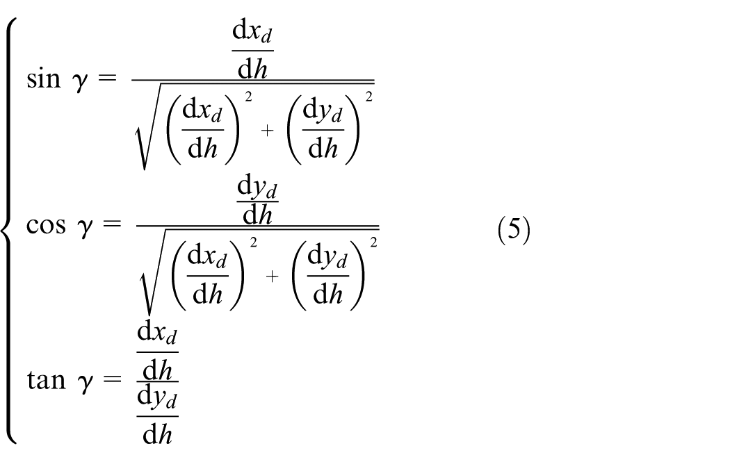
Substituting equation (5) and the partial derivatives of

The tooth profile of the spline/workpiece in the final rolling position is composed of equations (2) and (6).
Transmission ratio, instantaneous center, and centrodes
Under center distance a, the tooth profile (

where

where v is the feed-in speed of rolling die,
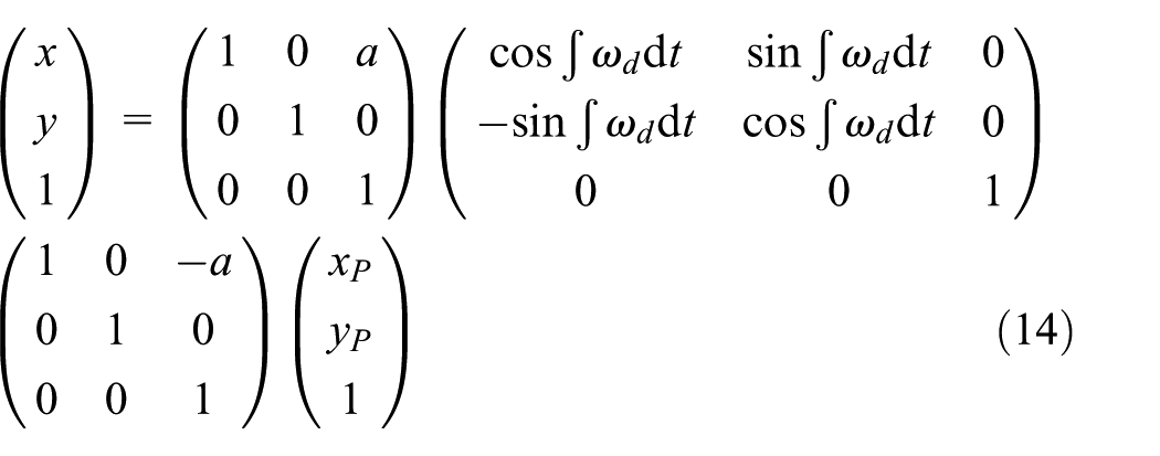
The coordinate system
The tooth profile

Substituting the expressions of
According to the meshing equation (equation (10)) in plane meshing, the common normal line of the tooth profiles at point M should pass the instantaneous center point P at this time 17

where
In the coordinate system Oxy, the common normal line at point M can be expressed as follows
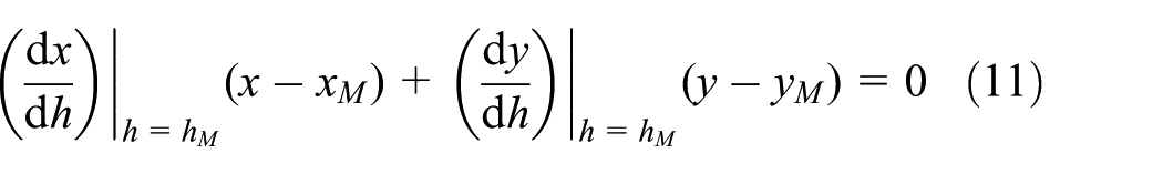
In the coordinate system Oxy, the line

The intersection P is the instantaneous center of rotation, and thus the transmission ratio i under center distance a can be expressed as follows17,18

The angular velocity of the rolling die is
Then, the centrode of the workpiece can be expressed as follows

Application for rolling process of involute spline with circular dedendum
In general, the spline cold rolling process has been used to form circular dedendum spline, where one knuckle curve connects two involute flanks to dedendum circle. Correspondingly, a knuckle curve connects two flanks to addendum circle of the rolling die. The discussion in this section is based on these profiles. The spur-involute spline is discussed in this section, and the basic parameters used in this section are listed in Table 1.
Basic parameters for involute.

Tooth profiles
In the rolling process for the involute spline with circular dedendum, the tooth profile (

where
In the final rolling position, taking

where
According to equation (17), the

Substituting the differentiation of equation (18) into equation (5), then the following expression would be obtained

that is

Then, the involute flank
In the final rolling position, the coordinate of center (
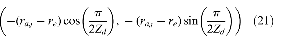
Then,
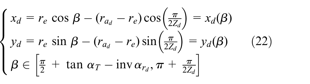
Substituting the differentiation of equation (22) into equation (5), then the following expression would be obtained

that is

Then, the circular dedendum
The above calculations were carried out under MATLAB software environment, and Figure 4 illustrates the tooth profiles of the die and workpiece in the final rolling position, where coordinate system Oxy is adopted.
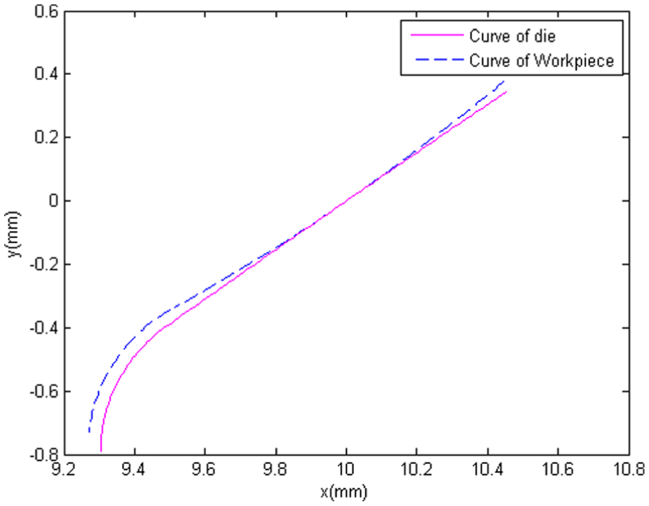
Tooth curves of the die and workpiece in the final rolling position.
Models for rolling process of circular dedendum spline
At the initial forming stage, the involute flank of the workpiece is not formed; after a certain amount of feed-in of the rolling die, the involute flank of the workpiece is formed. 3 At the forming stage where the workpiece only has circular dedendum, a circular arc meshing motion occurs; with the decrease in center distance, the involute flank of the workpiece has been formed, and then involute meshing motion occurs. The different meshing motions are based on different expressions of tooth curves, and thus the models of motion characteristics are also different.
With the increase in the amount of feed-in of the rolling die, the center distance between the die and the workpiece decreases, and the tooth height of the workpiece increases. Thus, there is a critical center distance
Under center distance a, dedendum circle radius of workpiece is

where
The involute flank section of the workpiece is similar to the modified gear, and thus the expressions of

where
Under center distance a, the tooth profile of the rolling die contacts with and is tangent to tooth profile

Workpiece only with circular dedendum
At the initial forming stage where the workpiece only has circular dedendum, the coordinate of contact point is

where there are three unknowns with three equations, so the unknowns including

where

When the workpiece only has circular dedendum, the instantaneous center P in the coordinate system Oxy can be expressed as follows

Then, at center distance a, the transmission ratio
Workpiece with involute flank
At the forming stage where the workpiece is with involute and circular dedendum, the coordinate of contact point is

where there are three unknowns with three equations, so the unknowns including
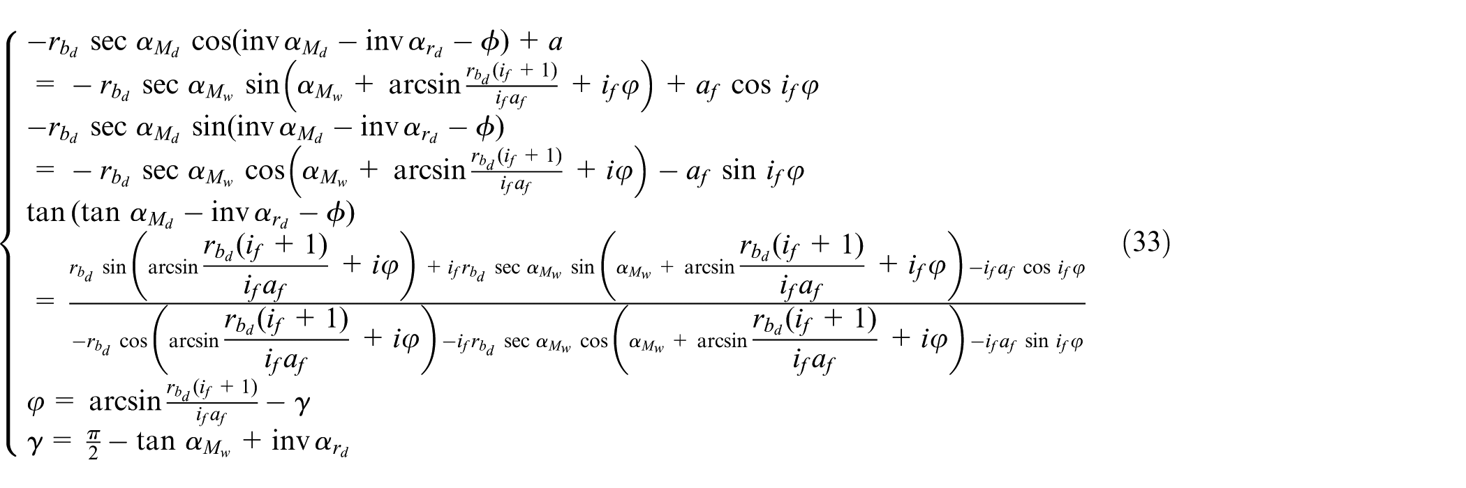
When the workpiece is formed with the involute flank, the instantaneous center P in the coordinate system Oxy can be expressed as follows

Then, the transmission ratio
Results and discussion
Under MATLAB software environment, a calculation program was developed to obtain the relevant data. Figure 5 illustrates the contact point and instantaneous center at different forming stages where the workpiece has different curves.
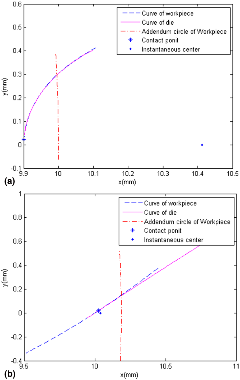
Contact point and instantaneous center at different stages: (a) workpiece only with circular dedendum and (b) workpiece with involute flank.
When the workpiece is formed only with circular dedendum, the contact point is far from the instantaneous center, and the instantaneous center is generally outside of addendum circle of the workpiece. Conversely, when the workpiece with the involute flank, the contact point is close to the instantaneous center, and the instantaneous center is generally inside of addendum circle of the workpiece. Because of this, the change in the instantaneous center at former stage is larger than that at latter stage, as shown in Figure 6.

x Axial coordinate of instantaneous center in rolling process.
In the forming process, the changes in the instantaneous center and transmission ratio are shown in Figures 6 and 7, respectively. There is a notable difference for two forming stages. With the decrease in center distance, the instantaneous center moves along negative x-axis and the position of the instantaneous center remains the same after the rolling die stops feed-in in the radial direction.

Transmission ratio in rolling process.
At the stage where the workpiece is only with circular dedendum, the changes of the instantaneous center and transmission ratio are notable, and the x axial coordinate of the instantaneous center reduces and the transmission increases about 1.3701%.
However, at the stage where the workpiece is formed with the involute flank, the instantaneous center varies slowly, and the transmission ratio has a slight decrease which is about −0.0007%. The change of transmission ratio at this stage is consistent with the transmission principle of involute gearing.
The different curve meshing is the main reason for a remarkable difference of the change in the instantaneous center or transmission ratio at the two forming stages. Under the parameters used in Figure 7, the difference of the transmission ratio is about 3.0211% when the workpiece only with circular dedendum turns into the workpiece with the involute flank.
Figure 8 illustrates the centrodes for the rolling die and the workpiece in the rolling process, and it can be found from the figure that the centrodes are not closed in the changing process of the center distance. Before rolling die stops feed-in in the radial direction, the centrode of the workpiece is an Archimedes line where the polar radius reduces. The centrode is determined by the instantaneous center. The position of the instantaneous center has a notable change when the workpiece only with circular dedendum turns into the workpiece with the involute flank, so the centrode also has a notable change at this moment, as shown in Figure 8(c).
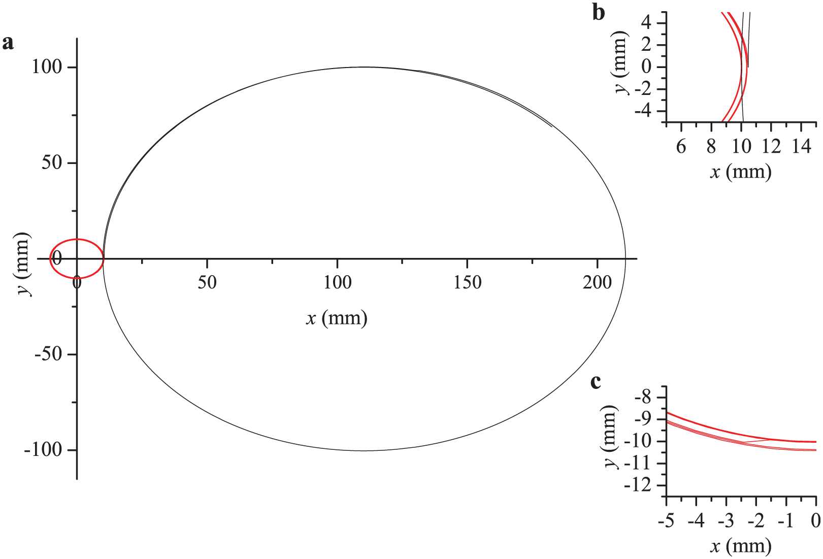
Centrodes in the spline rolling process: (a) centrodes of rolling die and workpiece, (b) enlarging area at initial stage, and (c) enlarging area for workpiece.
The polar radius of the centrode for the rolling die almost remains unchanged at the stage where the workpiece is only with circular dedendum, and the centrode for the rolling die is similar to Archimedes line at the forming stage of the workpiece with the involute flank, where the polar radius reduces with the decrease in center distance, as shown in Figure 9. The rotary center of the rolling die moves along negative x-axis with the decrease in center distance. Thus, the later centrode for the rolling die may be outside of the initial centrode, as shown in Figure 8(b). When the workpiece only with circular dedendum turns into the workpiece with the involute flank, the polar radius of the centrode of the rolling die increases. However, rotary center of the rolling die moves toward workpiece and the radius of the rolling die is much larger than the radius of the workpiece, and then the change of centrode at this moment is not as sharp as that for the workpiece.

Polar radius of centrode and rotary center for rolling die.
In order to keep the synchronization rotation between the workpiece and die, an additional kinematic compensation is implemented for the workpiece over the process. The angular velocity of the workpiece over the whole rolling process was determined by the changing transmission ratio and the angular velocity of the rolling die, as shown in Figure 10.

Kinematic compensation for workpiece in the rolling process.
Conclusion
Based on the principle of plane meshing and the processing characteristic of spline rolling, mathematical models of instantaneous center, transmission ratio, and centrodes in the spline rolling process under continuously varied center distance have been developed. Application of the developed models to investigate the rolling process of the involute spline with circular dedendum has been carried out, and the following conclusions can be drawn:
With the feed-in of the rolling die in the radial direction, the center distance between the die and workpiece decreases, and the instantaneous center moves along negative x-axis. The position of the instantaneous center varies sharply at the stage where the workpiece is only with circular dedendum.
The transmission ratio increases at first and then decreases with the decrease in center distance. The transmission ratio increases when the workpiece is only with circular dedendum, and the decrease in the transmission ratio when the workpiece is with the involute flank can be neglected, and there is an interruption between two stages.
The centrode of the workpiece is an Archimedes line, where the polar radius is reducing. The polar radius of the centrode of the rolling die almost remains unchanged at the stage where the workpiece is only with circular dedendum, and the polar radius is reducing with the decrease in center distance after that stage.
Footnotes
Appendix 1
Appendix 2
Academic Editor: David R Salgado
Declaration of conflicting interests
The author(s) declared no potential conflicts of interest with respect to the research, authorship, and/or publication of this article.
Funding
The author(s) disclosed receipt of the following financial support for the research, authorship, and/or publication of this article: The authors would like to gratefully acknowledge the supports of the National Natural Science Foundation of China (grant no. 51305334), National Natural Science Foundation of China for key program (grant no. 51335009), China Postdoctoral Science Foundation (grant no. 2014T70913), Shaanxi Province Natural Science Foundation of China (grant no. 2014JQ7273), and Science and Technology Planning Project of Suzhou, China (grant no. SYG201447).