
Abstract
We propose a bi-directional electrohydrodynamic pump developed for transporting dielectric liquid, where the electrodes are symmetrically configured but the applied voltage is non-symmetric. The underlying principle for liquid transport comes from the so-called Onsager effect, which states that the ion concentration is increased as the electric field is increased. Multi-physics software is used to perform numerical simulation for the fluid flow, the electric potential, and the transport of ion concentrations for two kinds of electrode patterns. A flow-visualization experiment is also conducted to verify the physical models and numerical methods employed. It is found that significant reduction of the ion recombination constant is required to get matching of the experimental and simulation results. We demonstrate through a parametric study that there is an optimum distance between two large grounded electrodes for producing a maximum pumping velocity at the diameter of two small electrodes fixed at 0.3 mm. The effect of the size of large grounded electrodes on the pumping performance is also studied in terms of streamlines, electric field, and charge distribution. A general account is also given of the basic ideas of electrode arrangement for the enhancement of pumping.
Introduction
How to pump fluids in the transport system of mini- and micro-scales has become a very important issue. In a lab-on-chip or micro-total analysis system (
Recently, pumping of dielectric liquid with low permittivity is suggested as a new method in particular for cooling of micro-electronic components.12–16 It is free of noise, vibration, bubble generation, and electrode degradation. The underlying principle for the pumping of dielectric liquid comes from the electrohydrodynamic (EHD) flow caused by the Onsager effect. When a certain amount of surfactant is added to a dielectric liquid containing unknown impurities, free ions are created in the form of reverse micelles, the concentration of which increases with the local electric field intensity, leading to the creation of charge (the Onsager effect); for more detailed explanation on the fundamentals of EHD flows and related literature, refer to Suh. 17
Initial studies on EHD pumps driven by the Seyed-Yagoobi group (see the review article 18 and references therein) were motivated by the need to enhance heat transfer in pool boiling and heat pipes, where working fluids are characterized by relatively low permittivity. Recently, they demonstrated the feasibility of applying the EHD pump to heat exchangers under a zero- or micro-gravity environment. 19 Their numerical model for the ion transport includes ion dissociation and recombination, but the Onsager effect has not been considered and the fluid flow is assumed to be driven only by the counter-charge in the dissociation layer (DSL). On the contrary, some fundamental studies on the EHD flows in dielectric fluid have neglected the effect of thin DSLs near the electrodes. 20
A variety of parameters are involved in the performance of the EHD pump, such as shape, arrangement and size of electrodes, applied electric field, and various fluid properties. Jeong and Seyed-Yagoobi21,22 employed a needle-type electrode as the anode and a ring-type electrode as the cathode (also used in Pearson and Seyed-Yagoobi 18 ). Later, a combination of a ring-type and a perforated electrode was used.23,24 In their studies, however, the contribution of the bulk-driven flow to the EHD pumping was not considered. The combination of saw-tooth and planar electrodes employed in Seo et al. 12 and Kim et al. 15 also carries a similar concept as to the enhancement of pumping performance. Recently, in view of its easy fabrication, EHD pump with planar electrodes has been studied.25,26 Even a symmetric pattern of the electrode arrangement is shown to produce a unidirectional pumping, which is attributed to the mismatch of mobility for positive and negative ions. 26 The needle-type or perforated or planar electrode somehow involves unavoidable geometrical singularity, which is a disadvantage in developing a mathematical model for the ion or charge creation and transport. Circular electrodes are free from such singularity. In Hojjati et al., 27 a series of symmetrically arranged circular cylinders of equal size were used to pump dielectric liquid in an open circulating channel. It was demonstrated that mismatch of ion mobility between cations and anions can yield a unidirectional flow. Very recently, three identical circular electrodes were used in a straight channel to demonstrate both experimentally and numerically that unidirectional pumping can be achieved if the electrodes are asymmetrically arranged. 28 However, the effects of various parameters, not least the geometrical factor, are yet to be explored.
Effect of the external field intensity on the EHD pumping velocity (or pumping flow rate) reported in the literature is found to have a common pattern regardless of the data source. The pumping velocity remains at a low level for small applied-field intensity. After a turning point, however, it increases in a linear fashion with the field intensity.12,15,18,26,27 Shown in Gharraei et al. 26 and Hojjati et al. 27 is the existence of a second turning point beyond which the flow rate tends to a saturated value. No plausible explanation for such variation exists yet. On the other hand, the asymptotic analysis of Suh et al. 29 predicts that the bulk-driven flow velocity and the DSL-driven flow velocity increase with field intensity to the cubic and fourth power, respectively, of the field intensity. Since the DSL-driven flow is counter-active to the bulk-driven flow, it may happen that the former overtakes the latter at high electric field so that the rate of increase in the pumping velocity monotonically decreases with the field intensity.
Effect of other fluid properties, such as ion concentration, ion-recombination constant, and mobility on the EHD pumping, has not been treated yet. The concept proposed in Suh et al. 29 and Suh and Baek, 30 together with the corresponding formula for the velocity, that the EHD flow field is determined from the competition between the bulk-driven and DSL-driven flow should be useful in exploring the qualitative and quantitative features of EHD pumps in terms of parameter variation.
In this study, we propose a bi-directional EHD pump with a simple arrangement of electrodes of a circular cylinder. The feasibility of dual-direction pumping has been demonstrated in, for example, Lemke et al. 31 and Chee et al., 16 but these studies required mechanical actuators and valves, fabrication of which may not be so easy on a small scale. Use of induced-charge electro-osmosis via biased direct current (DC) combined with alternating current (AC) voltage is proposed in Islam and Reyna 32 for a bi-directional pump. In that study, however, deionized (DI) water is used as the pumping medium and thus, the mechanism of the pumping is of course different from the present study. We in this study propose a bi-directional EHD pump composed of circular-cylindrical electrodes in a circulating channel of annular shape and explore the effect of key geometrical parameters, that is, electrode arrangement and size, on the pumping velocity. The rest of this article is organized as follows. Section “Geometrical configuration and flow-visualization experiment” describes the geometrical configuration of the electrodes employed in the design of our proposed bi-directional pump and the experimental methods used for flow visualization. Section “Numerical analysis” presents the governing equations for the fluid flow and ion transport and the numerical methods for solving them. In particular, we address how the parameters associated with the ion transport are set for the best matching between the experimental and numerical simulation results. In section “Basic idea on the principle and development of EHD pump,” basic ideas to be applied for developing new EHD pumps or for enhancement of their performance are explained, which are also useful in understanding the numerical results as well as the experimental data presented in section “Numerical and experimental results and discussion” for two kinds of electrode patterns. Finally, we summarize important findings of the study in section “Conclusion.”
Geometrical configuration and flow-visualization experiment
Figure 1 shows the experimental arrangement for visualization of EHD flow of the dielectric liquid dodecane (No. 297879; Sigma-Aldrich) inside an annular channel having several cylindrical electrodes symmetrically arranged so as to make the bi-directional pumping possible. The surfactant Span80 (No. 85548; Sigma-Aldrich) was added to the liquid in 0.5 wt% in order to control the concentrations of the free ions. For flow visualization, we also mixed in the liquid a small amount of nylon fluorescence particles with the average diameter of 7

Schematic diagram of the experimental arrangement and two kinds of electrode patterns used for visualization of the EHD flows inside a annular channel: (a) experimental apparatus: two kinds of electrode pattern with (b) four (pattern A) and (c) seven (pattern B) electrodes, where the filled circles indicate the anode; (d) top view of the annular channel used as a bi-directional pump, where the diamond shape described by dash-dot lines around the electrodes indicates the boundary of image frames the camera has taken for the streamline patterns and the line denoted by the coordinate s in the upper side indicates the section at which the velocity data are calculated from the PIV technique.
Tungsten wires are inserted through drilled holes into the top and bottom plates to be used as electrodes. The flow rate and the direction of liquid pumping within the channel mainly depends on the pattern of electrode arrangement as well as the way electrical potentials are applied on multiple electrodes. In this study, we consider two kinds of electrode patterns, A and B, as shown in Figure 1(b) and (c). The pattern A consists of two small electrodes, one on the left-hand side (LHS) as the anode and the other as the cathode, and two large electrodes, both as the cathode. The diameter of the small electrodes (e.g. PC and GC for pattern A; see Figure 1(b)) is fixed at
Before doing the main experiment, we washed the channel and electrodes by immersing them three times in water mixed with a detergent and then in pure water, after which they were dried. Electrodes were inserted into pre-drilled holes and the electric wires were connected. The whole apparatus was then put on a larger container and the liquid was poured. The DC voltage was applied using a high-voltage power supply (Model 610E; TREK Inc.). As soon as a DC voltage difference
Numerical analysis
Governing equations
Equations governing the steady flow in the annular channel read


where
Electric potential V is determined by the Poisson equation

where
The ion concentrations are determined by the Nernst–Planck equations

where

In addition,

where

In this numerical simulation, we use for simplicity the two-term expansion, that is, RHS of equation (7), in evaluation of the Onsager function. As usual, the recombination constant

with the reduction factor
Numerical methods
We used the multi-physics code COMSOL to numerically solve the system of equations (1) through (4). Solving the given multi-physics problem using other kinds of program, including the in-house code, may not be practically relevant, because so many variables involved in the formulation would definitely tend to cause the numerical instability, which is not thought to be easily resolved. Even with COMSOL, we underwent significant trial-and-errors to overcome such numerical instability, part of which has been explained in our previous studies.29,30
When the original form of the ion transport equations, that is, equation (4), has been used in the numerical simulation, it is found to cause a numerical instability.
30
Thus, following our previous study,
30
in order to overcome such instability problem, we set the concentrations
The triangular and tetra meshes are used for the two-dimensional (2D) and three-dimensional (3D) calculations, respectively. Very fine grids are built near the electrodes in such way the thin DSLs can be well captured. No-slip and impermeable conditions are applied as the velocity boundary conditions on the channel walls and electrode surfaces. The anodes are applied with a constant DC voltage
Parameter setting
There are several geometric parameters associated with the electrode arrangement. In order to make the bi-directional pumping possible, we must keep the symmetry of the electrode pattern. Thus, we have three parameters to be considered as shown in Figure 1(b) and (c): the diameter of large electrodes, D; the gap between large electrodes, H; and the gap between small electrodes, W. We fix the diameter of the small electrodes at
There are also several parameters related to the material properties to be specified for the calculation. Following our previous studies,29,30 we determine the relative permittivity, ionic radius, and zero-field concentration for the dielectric liquid, that is, dodecane mixed with Span80 in the 0.5 wt%, as
The reduction factor for the recombination constant,

Effect of the reduction factor
Basic idea on the principle and development of EHD pump
Before presenting the experimental and numerical results, we address the fundamental mechanism of EHD pumping, which can be utilized in development of new EHD pumps or their enhancement. First, we must be able to estimate the charge distribution in the bulk. Following the asymptotic analysis,
29
under the assumption of equal mobility and small values of the dimensionless parameters,

where

Schematic of electric field lines (thin solid lines with open arrows), net-charge distribution (circles with + and − signs), and forces (filled arrows) acting on the charges around a pair of electrodes of different sizes illustrating the mechanism of EHD pumping from the smaller to larger electrode. Also shown are the local unit vector set
Next, we must be able to estimate the fluid flow and EHD pumping from the charge and electric field distributions. The Coulomb force density, the driving term in the momentum equation (2),
The dominant parameter affecting the increase in the pumping capacity is of course the electric field. However, under the assumption of fixed level of electric field, the pumping capacity depends on how the electrodes are spatially arranged. When we endeavor to enhance the pumping capacity under a fixed potential
On the other hand, DSLs near electrodes exert adverse influence on the pumping effect because much more concentrated counter-ion concentrations in the thin DSL give slip velocity opposing the bulk-driven flow. The effect of DSL-driven flow is increased as the recombination constant
Numerical and experimental results and discussion
Parametric study with electrode pattern A
We conducted the grid-dependence test to get a suitable mesh system. For this, we performed 2D simulation with the electrode pattern A at the parameter set,
Figure 4 shows the numerical results of U as a function of the gap between the large electrodes, H, for various diameters of large electrodes, D = 0.3, 0.7, 1.5, 2.0, 2.5, and 3.0 mm. We find that at a fixed value of D, the mean velocity initially increases with H showing a maximum value at a critical value of H, ranging from 2.5 to 3 mm, and then decreases with H after that. Obviously, when H is smaller, the flow passage between the large and small ground electrodes should be more narrowed leading to increase in the viscous friction and decrease in the flow rate. On the contrary, when the gap is too large, the effect of large electrodes on the electric field will become weaker and the electric field tends to be symmetric yielding decreased net flow along the channel. So, we can expect the existence of a critical value of H at which the mean velocity becomes maximized.
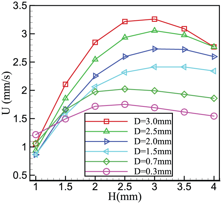
Variation in the mean velocity with H obtained from 2D numerical simulation for the pattern A at W = 0.6 mm with six values of the large electrode diameter, D = 0.3, 0.7, 1.5, 2.0, 2.5, and 3.0 mm.
Figure 4 also reveals that the maximum mean velocity increases with D. This can be understood with the aid of the discussion given in section “Basic idea on the principle and development of EHD pump.”Figure 5 shows comparison of two streamline patterns obtained at D = 0.3 mm and D = 3 mm. We can see that for the case with D = 0.3 mm, many streamlines recirculate around GB and GT, and those streamlines contributing to the pumping are less compared with D = 3 mm. A more fundamental reason for this can be given with the aid of the contours of ion-concentration difference,

Streamlines around electrodes obtained numerically at

Contour lines of the concentration difference (solid lines),
We next investigate the effect of W on the mean velocity. The numerical results obtained at two values of D are presented in Figure 7 as a function of H. The plots also reveal that the mean velocity is maximized at a critical value of H, ranging from 2.5 to 4.0 mm. The mean velocity is shown to monotonically increase as W is decreased for both diameters, which is simply attributed to the higher field at closer distance between PC and GC leading to larger charge density, larger Coulomb force, and stronger EHD flow.

Variation in the mean velocity with H obtained from 2D numerical simulation for the pattern A at (a)
Figure 8 shows the monotonic increase in the mean velocity with decrease in W for a fixed set of D and H. Figure 8 also presents the pump efficiency defined as
where Q is the flow rate per unit depth of the channel and

Here,
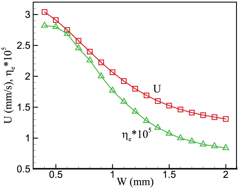
Mean velocity U and pumping efficiency
Figure 9 depicts the dependence of the mean velocity on the applied voltage obtained numerically at D = 3 mm, H = 3 mm, and W = 0.6 mm. At low voltage, the mean velocity is shown to increase with the field intensity like
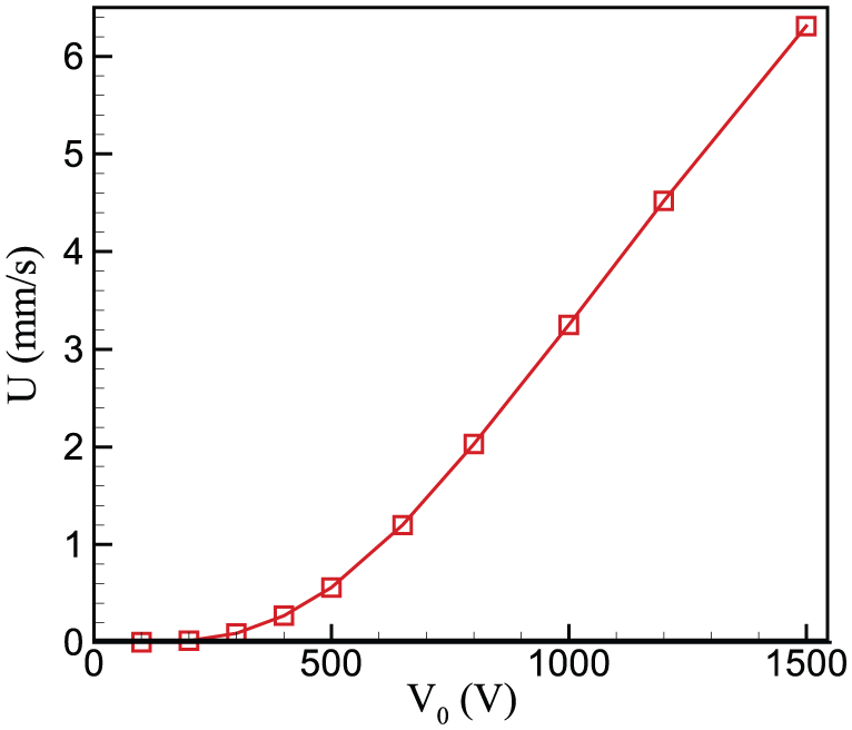
Mean velocity U versus applied voltage
Comparison between the experimental and numerical solutions with electrode pattern A
A visualization experiment was conducted for the pattern A at H = 3 mm and W = 0.6 mm with D = 0.3, 1, and 2 mm. Figure 10 shows the distribution of the stream-wise velocity component obtained along the channel section denoted by the coordinate s exhibited in Figure 1(d). The experimental data are obtained from the conventional PIV technique applied to the trace of particles of the average diameter 7

Numerical and experimental results of the stream-wise velocity distribution along the coordinate s (indicated in Figure 1(d)) obtained at H = 3 mm and W = 0.6 mm for the electrode pattern A with D = 0.3, 1, and 2 mm. (a) D = 0.3 mm, βL = 0.026; (b) D = 1 mm, βL = 0.024; and (c) D = 2 mm, βL = 0.024.
Comparison of the fully developed velocity profiles between the experimental and numerical results at the channel section far away from the electrodes is not enough for complete verification of the numerical simulation because even erroneous physical models applied to the EHD pumping can yield a matched fully developed velocity profile, which is parabolic regardless of the physics occurring in the region of the electrodes. Thus, we visualized the streamline patterns around the electrodes as shown in Figure 11 to verify the numerical results. Overall, the numerical streamlines well follow the experimental results. The converging and diverging patterns of the streamlines in the upstream and downstream, respectively, of the electrodes PC and GC and the vortical flows around the electrodes GT and GB are well captured by the numerical simulations, implying that the physical models for ion dissociation and recombination and the simulation methods are qualitatively correct.

Comparison between the experimental (LHS) and numerical (RHS) streamlines obtained at W = 0.6 mm and H = 3 mm for (a) D = 0.3 mm, (b) 1 mm, and (c) 2 mm (with its magnified view in (d)) around the electrodes of pattern A. The frame taken for showing these plots is indicated by dash-dot lines in Figure 1(d).
We have seen that the rate of ion recombination should be taken usually much smaller than that proposed by Langevin for the enhanced comparison between the experimental and numerical results. The same trend has also been observed in our previous studies on the more fundamental problems.29,30 As suggested in Suh and Baek, 30 however, the reason for the relevance of such reduction of recombination constant should be explored based on statistical and physico-chemical knowledge apart from the scope of mechanical engineering.
Experimental and numerical results with electrode pattern B
The numerical results with the pattern B (Figure 12) also reveal that the mean velocity is maximized at a critical value of H, except for the case with D = 0.3 mm showing a monotonic increase in U with H. Figure 12 also shows increase in U with D, like the case with the pattern A. Most importantly, the magnitude of the mean velocity is more than double that of the pattern A at an equal parameter set; for instance, we get U = 2.01 mm/s with pattern A at D = 0.7 mm and H = 2.5 mm, whereas we get U = 4.91 mm/s with pattern B at the same parameter set, the latter being 2.44 times the former. This suggests that simply building a series of electrode pattern across the channel can enhance the pumping performance.

Variation in the mean velocity with H obtained from 2D numerical simulation for the pattern B at W = 0.6 mm with three values of the large electrode diameter, D = 0.3, 0.7, and 1 mm.
Experiment for the pattern B was conducted only for the case with D = 1 mm. Figure 13 presents the distribution of stream-wise velocity component along the s-direction depicted in Figure 1(d). The numerical result is very close to the parabolic shape, but the experimental profile is somewhat asymmetric with respect to the centerline of the channel showing a slightly larger magnitude on the outer side (s > 5 mm) than on the inner side (s < 5 mm) of the channel. Maximum deviation of the numerical velocity from the experimental one amounts to 28% near s = 5 mm. Such a discrepancy should be of course decreased at a lower value of

Numerical and experimental results of the stream-wise velocity distribution along the coordinate s (indicated in Figure 1(d)) obtained at D = 1 mm, H = 3 mm, and W = 0.6 mm for the electrode pattern B. Here, the numerical results are obtained with
Shown in Figure 14 are the experimental and numerical streamline patterns for the electrode pattern B. Here too, the numerical results well predict the experimental ones, such as the diverging and converging structure of the fluid streams and the vortical-flow pattern around the electrodes. In particular, the recirculating flow around the large grounded electrode located at the center is significantly weaker than the ones around the other two near the channel walls, which is mainly responsible for the significant increase in the pumping velocity compared with the pattern A.

Comparison between the experimental (LHS) and numerical (RHS) streamlines obtained at D = 1 mm, W = 0.6 mm, and H = 3 mm around the electrodes of pattern B. The frame taken for showing this plot is indicated by dash-dot lines in Figure 1(d).
Conclusion
We propose in this study a two-way EHD pump with simple arrangement of circular-cylindrical electrodes. The pumping velocity is obtained with 2D numerical simulations at various sets of geometrical parameters. The numerical results are in good agreement with the experimental ones in terms of the streamline patterns around the electrodes, which turned out to be basically of a 2D character. In the numerical simulations, the recombination constant must be lowered significantly from that of the Langevin’s formula for the qualitative matching between the two, but there is a limit due to the numerical instability. We address the basic concepts to be considered regarding the electrode arrangement so as to achieve higher pumping flow rate. It is shown that under the restriction of symmetrical electrode pattern required for the bi-directional pumping, there exists an optimum distance between the large grounded electrodes that provides a maximum flow rate. Increased size of the large electrodes is shown to enhance the pumping effect because the level as well as the influential range of the Coulomb force created near those electrodes opposing the EHD pumping is decreased with the electrode size. Decreasing the gap between a pair of small electrodes on the other hand results in monotonic increase in the mean velocity simply due to the increase in field intensity leading to the increased Coulomb force. The pumping efficiency remains very low since the annular channel considered in this study requires a very low level of pressure difference across the region of the electrode pattern for the fluid circulation. Numerical and experimental streamlines are also in good agreement with each other for the electrode pattern B. The flow rate with the pattern B turned out to increase more significantly than expected compared with the pattern A, because the recirculating flow around the central large electrode is much weaker than the other two near the channel walls.
Footnotes
Appendix 1
Acknowledgements
The first version of this article has been read by Professor M. Duffy.
Academic Editor: Bo Yu
Declaration of conflicting interests
The author(s) declared no potential conflicts of interest with respect to the research, authorship, and/or publication of this article.
Funding
The author(s) disclosed receipt of the following financial support for the research, authorship, and/or publication of this article: This work was supported by the Human Resources Development of the Korea Institute of Energy Technology Evaluation and Planning (KETEP) grant funded by the Korean government Ministry of Knowledge Economy (No. 20134010200550).