
Abstract
Recently, an offshore support vessel is being widely used to install an offshore structure such as a subsea equipment which is laid on its deck. The lifting operation which is one of the installation operations includes lifting off, lifting in the air, splash zone crossing, deep submerging, and finally landing of the structure with an offshore support vessel crane. There are some major considerations during this operation. Especially, when lifting off the structure, if operating conditions such as ocean environmental loads and hoisting (or lowering) speed are bad, the excess of tension of wire ropes of the crane and the collision between the offshore support vessel and the structure can be occurred due to the relative motion between them. To solve this problem, this study performs the lifting simulation while the offshore support vessel installs the structure. The simulation includes the calculation of dynamic responses of the offshore support vessel and the equipment, including the wire tension and the collision detection. To check the applicability of the simulation, it is applied to some lifting steps by varying operating conditions. As a result, it is confirmed that the conditions affect the operability of those steps.
Keywords
Introduction
The particular characteristics of an offshore structure are not like those of an onshore or near-shore structure. Therefore, it cannot be constructed in its operating site and is being built in shipyard, transferred, transported to the site, and finally deployed at there. There are various methods to transfer, transport, and deploy it.
The transfer operation is to move the offshore structure from shipyard to means of transport such as a transport barge. The major methods for the transfer operation are the loading out method, the floating out method, and the lifting off method. The loading out method is to move an offshore structure onto a transport barge in the longitudinal or transverse direction of the barge. And the floating out method is to bring an offshore structure such as a jacket and a load tower fabricated in a dry dock afloat and to float it out from the fabrication site like the launching of a ship. Finally, the lifting off method is to lift off offshore structures such as an offshore module and a deck structure and to move it with an offshore support vessel (OSV) crane.
The transport operation is to transport the structure to its operating site with the means of transport. The major methods for the transport operation are the barge towing method, the self-floating towing method, and the self-propelled carrier transporting method. The barge towing method is to transport the structure which rests on the deck of a transport barge by several tugs. The self-floating towing method is to support the structure with not a transport barge but its own buoyancy and to push or pull it by tugs. And, the self-propelled carrier transporting method is to transport the structure which rests on the deck of a transport barge or an OSV with the propulsion of the transport barge or the OSV.
Finally, the deploy operation is to deploy the structure at its operating site. The major methods for the deploy operation are the floating over method, the launching method, and the lifting method. Both the floating over method and the launching method take the advantage of ballasting of a transport barge when deploying the structure. Especially, the launching method obtains the slope of the transport barge by ballasting and pulls the structure forward while the float over method mates the structure onto a fixed structure by changing the draft of the transport barge. In the case of the lifting method, the offshore structure is lifted and moved by an OSV crane. These methods for transfer, transport, and deploy operations are selected depending on some considerations such as the circumstances and characteristics of the structure to be installed. Also, each method has its own considerations during the operation.
As mentioned above, an offshore structure is transported to the actual operating site after constructed on shore. The transported structure is deployed in the way of something such as float over, launching, and lifting. Among them, the lifting method is usually carried out by an OSV and it consists of five steps, 1 as shown in Figure 1. There are some major considerations on each step in the lifting method. In the step of lifting off (Figure 1 (1)), an OSV lifts off the structure which is laid on the deck or the adjacent transport barge with its own crane. At this moment, there should be no collision between the structure and others resulting from the relative motion among them. In the step of lifting in the air (Figure 1 (2)), the lifted structure is moved to the specified position in the air. At this time, the severe and undesirable pendulum motion should be avoided, because it is very important to control the structure exactly. In the step of splash zone crossing (Figure 1 (3)), the structure penetrates the water surface. The varying buoyancy force and slamming impact force exerted on the structure should be considered in this step. In the step of deep submerging (Figure 1 (4)) in which the structure submerges deeply, the motion of the lifted structure, in response to wave-induced motion of the OSV crane tip, is important because of the possibility of resonance. In the last step of landing (Figure 1 (5)), the structure should be landed exactly and there should not be large impact which could cause damage to the structure.

Five steps of the lifting method by the OSV.
If we can simulate each step in the aspect of the above major considerations, the validity or operability of the given or planned operating condition can be verified. Thus, the physics-based simulation based on multibody system dynamics is performed for the former three steps (lifting off, lifting in the air, and splash zone crossing) of the lifting method in this study. Through the simulation, the tension acting on wire ropes of an OSV crane and the collision between the OSV and the structure are analyzed. At this time, various operating conditions such as ocean environmental loads and hoisting (or lowering) speed are applied to the simulation.
Related studies
There are some studies related to the simulation in the field of ship production. Cha et al. 2 proposed an integrated simulation framework for shipbuilding production. The proposed simulation framework provides an environment for developing various simulation systems for shipbuilding process planning. It consists of a simulation kernel, basic simulation component, and application-specific simulation component. Cha et al. 3 performed dynamic response simulation of a heavy cargo suspended by a floating crane. The dynamic equations of motions of the floating crane and the heavy cargo were considered by coupled equations, because the floating crane and the heavy cargo are connected by wire ropes and provide a force and a moment for each other. Also, the nonlinear hydrostatic force, the linearized hydrodynamic force, the wire rope force, and the mooring force were considered as external forces. And, they estimated the motion of the floating crane and the heavy cargo, and also calculated the tension acting on the wire ropes between the two. Ha et al. 4 developed a multibody system dynamics simulator for the process simulation of ships and offshore structures. The developed simulator consists of six components: the multibody system dynamics kernel, the force calculation kernel, the numerical analysis kernel, the hybrid simulation kernel, the scenario management kernel, and the collision detection kernel. They applied the simulator to various cases of the process simulation of the ships and the offshore structures.
There are also some studies related to the simulation in the field of offshore engineering, especially the lifting method for the deploy operation. Masoud 5 applied delayed-position feedback together with the luff-and-slew angle actuation to a crane vessel in order to control pendulum motion of a lifted structure in the air. And the effectiveness of this method was demonstrated with a fully nonlinear three-dimensional simulation and with an experiment on a 1/24 scale model. Boe and Nestegard 6 developed dynamic response equations of the lifted structure in deep water and described how these equations can be applied in order to establish limiting sea-states for the operation. Wu 7 analyzed dynamic responses of a template suspended by a floating crane through splash zone. He carried out dynamic and static analysis using the Simulation and Engineering Analysis of Marine Operations and Floating Systems (SIMA) which is a commercial program developed by MARINTEK. Ku and Roh 8 performed dynamic response simulation of an offshore wind turbine suspended by the floating crane. For this, they supposed that the motion of the floating crane and the wind turbine has 14 degrees of freedom, and considered the interactions among them by constraints. In addition, hydrostatic and hydrodynamic forces were considered as external forces acting on the floating crane. Through the simulation, they estimated the motion of the floating crane and the offshore wind turbine, and also calculated the tension acting on the wire ropes between the two. Vorhölter et al. 9 performed a time-domain analysis of typical lifting operations for the offshore wind industry. Three different vessels and two different load variations of the lifting operations were considered in the analyses. For this, they supposed that the motion of the vessel and the lifted structure has 8 degrees of freedom. And, they took not multibody system dynamics analysis but quasi-static analysis to analyze dynamic motion of the vessel and the structure. Through the analysis, dynamic motion of the vessel and the structure was derived, but wire tension and collision were not calculated.
Table 1 shows the summary of related studies about the lifting method for the deploy operation and the comparison of them with this study. As shown in Table 1, the studies mentioned above did not cover dynamic responses such as wire tension and collision, and various operating conditions such as ocean environmental loads and hoisting (or lowering) speed all for the steps of the lifting method. Thus, this study performs the physics-based simulation of the steps of lifting off, lifting in the air, and splash zone crossing while the OSV deploys the structure by the lifting method. The simulation includes the calculation of the dynamic responses of the OSV and the structure, including the wire tension and the collision detection between them.
Summary of related studies and comparison with this study.

O: Covered, X: Not covered.
Methodologies for lifting simulation
In this section, some methodologies that are required to perform the lifting simulation are described. Basically, the Newton’s second law might be applied to describe the motion of the OSV and the offshore structure.
Multibody system dynamics
A vessel-mounted crane can be regarded as a multibody system which consists of interconnected rigid bodies with joints and springs-like wire ropes. Thus, the equations of motion based on multibody system dynamics are required to analyze the motion of a crane system including the lifted object (e.g. offshore structure to be lifted by the OSV crane). In this section, the equations of motion based on the multibody system dynamics are explained. 10
The relative motion that is permitted between bodies in the multibody system is often constrained by connections between those bodies. Therefore, Newton’s equation of motion for the multibody system can be stated as follows

The vectors in equation (1) are represented in terms of the Cartesian coordinates.
The position vector

Differentiating equation (2) yields the velocity relation

where the velocity transformation matrix
Differentiating equation (3) yields the acceleration

Substituting equation (4) into equation (1), we can obtain the following equation

Multiplying both sides of equation (5) by

The constraint reaction forces are perpendicular to the path along which the bodies are constrained to move. This says that the constraint reaction force

where
Hydrodynamic force calculation
The lifting operation is carried out in offshore. Thus, hydrodynamic force would be exerted on an OSV and should be added to external forces of the equations of motion based on the multibody system dynamics. The hydrodynamic force can be divided into two parts, as shown in equation (8); the wave exciting force exerted by the incident wave and the diffraction wave, and the radiation force from the wave generated by the motion of the OSV itself


Calculation procedure of the hydrodynamic force.
Varying buoyancy force and slamming impact force
In the step of splash zone crossing, the buoyancy of an offshore structure is changed as it enters the water and a slamming impact force acts on the structure when it crosses the water surface, as shown in Figure 3. The buoyancy is related to the submerged volume of the structure by Archimedes’ principle. If the water surface changes, the submerged volume changes, as well. This leads to the change in buoyancy. In the simulation of the step of splash zone crossing, the water surface changes as the structure crosses the splash zone. Hence, the change in buoyancy should be considered. Also, the slamming impact force, that is, the impulsive force which frequently exerts on the structure due to the breaking wave, should be considered in the splash zone of structure. These two forces could be calculated by simplified methods presented in equations (9) and (10) 12


where

Varying buoyancy force and slamming impact force in the step of splash zone crossing.
Wire tension calculation
To lift an offshore structure by a vessel-mounted crane, the offshore structure and the crane should be connected by wire ropes. When the offshore structure is lifted, these wire ropes are extended and exert tension. On the other hand, when these wire ropes are not extended, they are loosened and exert no force. Thus, they could be modeled as incompressible springs which exert force only when extended. And the force by the incompressible springs is added to one of the external forces of the equations of motion based on the multibody system dynamics. The modeling of the incompressible spring force is shown in Figure 4.

Modeling of the incompressible spring force.
Collision detection
Collision is the major consideration in the lifting operation, especially in the step of lifting off. In the simulation of the step of lifting off, it should be checked by calculating the position of objects whether the objects collide with each other or not. And then, if the objects collide with each other, their motions should be changed. This study introduces collision detection13,14 to change the motions of the collided objects through changing the velocities of the collided objects. In this section, the process of collision detection in the case of two-dimensional (2D) collision is explained, as shown in Figure 5.

Configuration of the objects A and B colliding each other.
The collision detection handles collision by changing the velocity of the objects which collide before and after collision. First, to check whether some objects collide or not, the penetration depth is defined. The penetration depth means how much the objects which collide penetrate each other before collision process. The step to determine the penetration depth is “Collision check.” Also, in this step, the normal vector (
In the “Collision response” step, the linear velocity and angular velocity are changed by following equations (11) and (12)
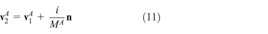

where subscripts 1 and 2 mean before and after collision, respectively. MA means the mass of the object A, IA means the moment of inertia of the object A, i means the magnitude of impulse by collision, and “·” operator means perpendicular dot product which means the magnitude of cross products of two vectors.
Equations (11) and (12) show how the collision affects pre-collision velocity of the object A. The equations for the object B are the same when i is replaced with −i. These equations can be obtained from Newton’s law of motion. According to Newton’s law of motion, the impulse is same with the change of momentum as following equation (13)

where
Dividing both sides of equation (13) by MA yields

The direction of

Transposing
Now, i in equations (11) and (12) can be obtained from Newton’s law of restitution. Newton’s law of restitution can be expressed as equation (16)

where e means coefficient of restitution.
And equation (16) can be expressed as equation (17) by substituting

where

Substituting equations (11) and (12) into equation (18) yields

By doing so for object B, equation (20) can be derived

Substituting equations (19) and (20) into equation (17) and transposing terms out about i yields
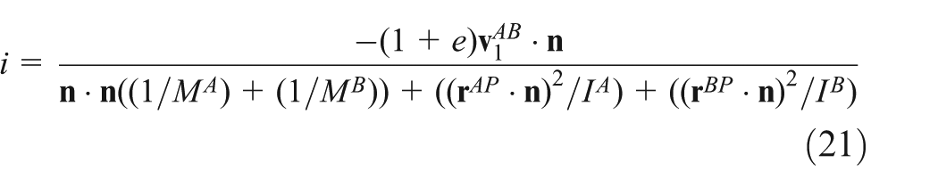
Finally, i can be obtained from equation (21). And the collision detection can be made using equations (11) and (12).
Lifting simulation of the offshore supply vessel
Problem definition
We developed an in-house program based on multibody system dynamics and the program was used for this simulation. With the use of this program, the dynamic responses of the OSV and the equipment, including the wire tension and collision detection can be calculated. This program was validated through various examples in our previous studies.4,15,16 Similar to these examples, this study simulated three steps (lifting off, lifting in the air, and splash zone crossing) of the lifting method. Through the simulation, the calculation of the dynamic responses of the OSV and the lifted structure (e.g. subsea equipment), including the wire tension and the collision detection between the OSV and the structure, was performed. Also, various operating conditions such as ocean environmental loads (wave height, wave period, and heading angle) and hoisting (or lowering) speed were applied to the simulation. Before the simulation, actual models of the OSV and the subsea equipment (simply, equipment) were idealized as simplified models, as shown in Figure 6. The configuration and specifications of them are shown in Figure 7 and Table 2, respectively.

Actual and simplified models for the simulation: (a) actual models and (b) simplified models.

Configuration of the simplified models for the simulation.
Specification of the OSV and the subsea equipment for the simulation.

OSV: offshore support vessel.
Simulation of the step of lifting off
In the simulation of the step of lifting off (Figure 1 (1)), the OSV lifted off the equipment which was laid on the deck with its own crane. Through this simulation, wire tension acting on wire ropes of the OSV crane was calculated according to ocean environmental loads and hoisting speed of the equipment. In addition, the possibility of collision was also checked because the possibility of collision is the major consideration on the step of lifting off. The simulation was performed for 200 s.
Variation of wave height
Table 3 shows the simulation results in which the wave height varies from 0.5 to 1.5 m, the wave period is 9.0 s, the heading angle is 0° (following sea), and the hoisting speed of the equipment is 0.1 m/s. In this table, a dynamic amplification factor (DAF) means a value of maximum dynamic load divided by static load. This static load means the weight of the equipment in the air. If there is no collision, it is “X” and otherwise, it is “O.” As shown in this table, the DAF was the highest in Case A03. There is no collision when the wave height is 0.5 and 1.0 m, but there is collision when the wave height is 1.5 m. Figures 8 and 9 show the simulation results of Cases A01 and A03, respectively. These figures show the change of wire tension as time goes. The lower graph is the magnified view of the moment when the equipment just starts to be lifted off in the upper graph in each figure. There is an abnormal point in the change of wire tension of Case A03 in which there is collision. This point is marked as the red circle in the lower graph of Figure 9. On the other hand, an abnormal point is not found in Case A01 in which there is no collision.
Simulation results by the variation of wave height in the step of lifting off.


Simulation results of Case A01 in the step of lifting off.
Simulation results of Case A03 in the step of lifting off.
Variation of hoisting speed
Table 4 shows the simulation results in which the wave height is 1.0 m, the wave period is 9.0 s, the heading angle is 0°, and the hoisting speed of the equipment varies from 0.02 to 0.06 m/s. As shown in this table, the DAF is the highest in Case A06. There is no collision when the hoisting speed is 0.06, but there is collision when the hoisting speed is 0.02 and 0.04 m/s. Figures 10 and 11 show the simulation results of Cases A04 and A06, respectively. These figures show the change of wire tension as time goes. The lower graph is the magnified view of the moment when the equipment just starts to be lifted off in the upper graph in each figure. There are abnormal points in the change of wire tension of Case A04 in which there is collision. On the other hand, an abnormal point is not found in Case A06 in which there is no collision and whose DAF is the highest.
Simulation results by the variation of hoisting speed in the step of lifting off.


Simulation results of Case A04 in the step of lifting off.

Simulation results of Case A06 in the step of lifting off.
Variation of wave period
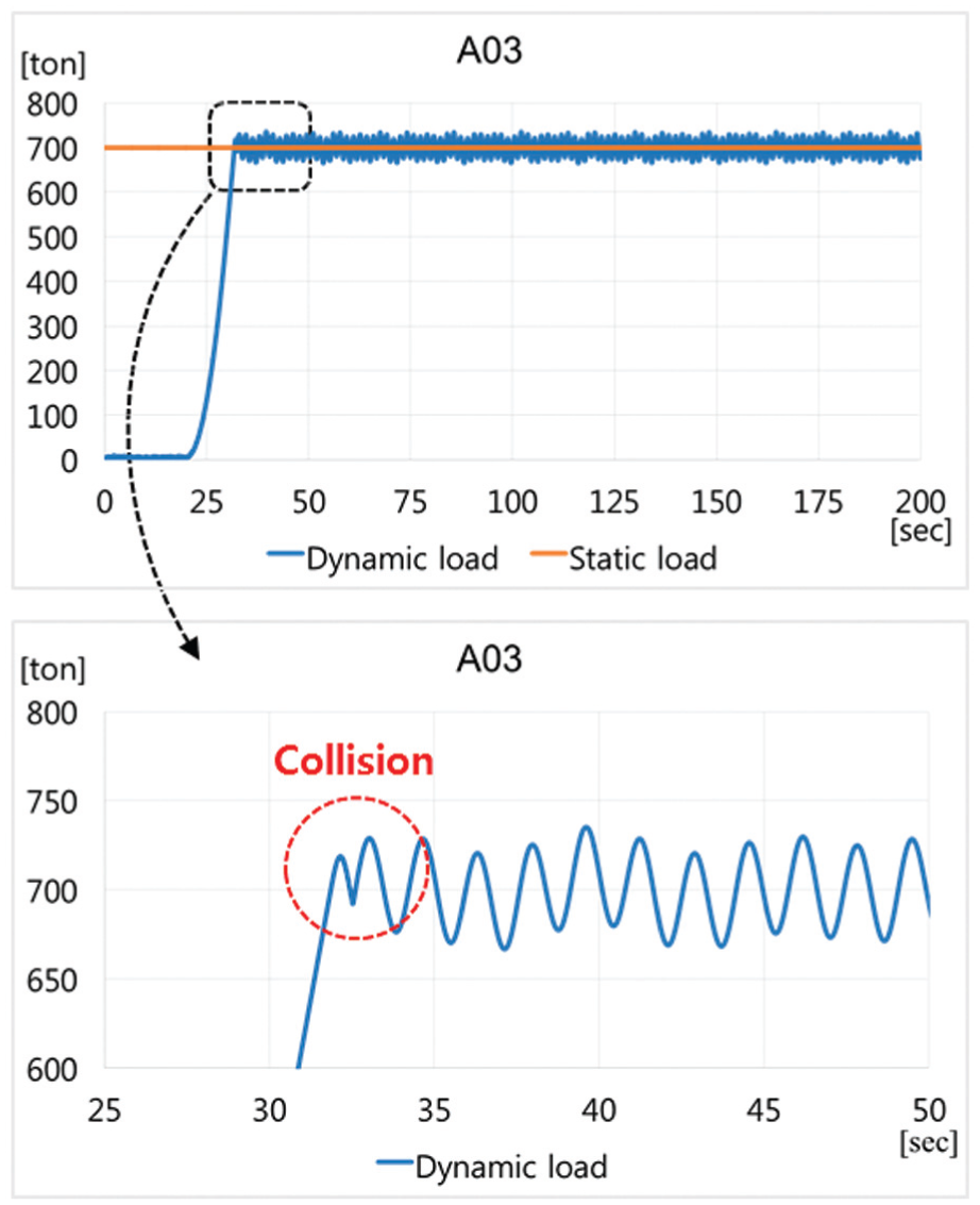
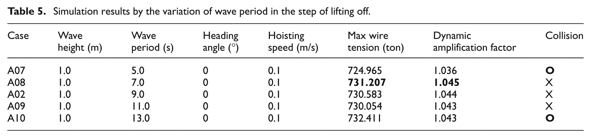
Table 5 shows the simulation results in which the wave height is 1.0 m, the wave period varies from 5.0 to 13.0 s, the heading angle is 0°, and the hoisting speed of the equipment is 0.1 m/s. As shown in this table, the DAF is the highest in Case A08. There is no collision when the wave period is 7.0, 9.0, and 11.0 s, but there is collision when the wave period is 5.0 and 13.0 s. Figures 12 and 13 show the simulation results of Cases A08 and A10, respectively. These figures show the change of wire tension as time goes. The lower graph is the magnified view of the moment when the equipment just starts to be lifted off in the upper graph in each figure. There are abnormal points in the change of wire tension of Case A10 in which there is collision. On the other hand, an abnormal point is not found in Case A08 in which there is no collision and whose DAF is the highest.
Simulation results by the variation of wave period in the step of lifting off.

Simulation results of Case A08 in the step of lifting off.

Simulation results of Case A10 in the step of lifting off.
Simulation of the step of lifting in the air
In the simulation of the step of lifting in the air (Figure 1 (2)), the OSV lifts the equipment in the air. Through this simulation, the pendulum motion of the equipment was checked according to various ocean environmental loads, because the pendulum motion is the major consideration on the step of lifting in the air. The simulation was performed for 150 s. Table 6 shows the simulation results for some operating conditions. In this table, the maximum traveling distance means the maximum value of the traveling distance of the equipment from its initial position. As shown in this table, the DAF is the highest in Case B04 and the maximum traveling distance of the equipment is also in Case B04. Figure 14 shows the simulation results of Case B04. The upper graph shows the change of wire tension as time goes and the lower graph shows the change of traveling distance of the equipment as time goes. The maximum traveling distance in Case B04 is marked as a red circle in the lower graph.
Simulation results by the variation of ocean environmental loads in the step of lifting in the air.


Simulation results of Case B04 in the step of lifting off.
Simulation of the step of splash zone crossing
In the simulation of the step of splash zone crossing (Figure 1 (3)), the equipment penetrates the water surface. Through this simulation, varying buoyancy force was calculated according to the position of the equipment during lowering and the slamming impact force was also calculated according to the lowering speed of the equipment. When calculating the slamming impact force, the slamming coefficient is very important. DNV-RP-C205 17 presented that for a smooth circular cylinder, the slamming coefficient can be taken as 5.15. Since the bottom of the equipment is cylinder shaped, this value was taken as the slamming coefficient in this simulation. This slamming impact force acts on the equipment once at the moment when the equipment penetrates the water surface in this simulation. That is, the slamming impact force acts for very short duration. However, it is not easy to get the duration. Thus, we assumed that the slamming impact force acts for the unit time of simulation (i.e. 0.01 s) in this simulation. In addition, wire tension acting on wire ropes of the OSV crane was calculated by considering these forces. The simulation was performed for 150 s. Table 7 shows the simulation results in which the lowering speed of the equipment varies from 0.25 to 2.0 m/s. Figure 15 shows the simulation results of Case 01. The upper graph shows the vertical position of the equipment as time goes and the lower graph shows the change of wire tension as time goes. In the lower graph, the wire tension changes and the aspect of the change of wire tension varies as the position of the equipment varies. The moments when the aspect of the change of wire tension varies are marked as Positions A, B, and C in the figure. Position A is when the equipment crossing the splash zone. As shown in Table 7, the faster lowering speed is, the shorter time to splash zone, the larger slamming impact force, and the larger change of wire tension when crossing are. Figures 16 and 17 show the change of wire tension when the equipment crosses the splash zone in Case C01 and Case C04, respectively. As shown in these two figures, we could check that the faster lowering speed is, the larger change of wire tension and the more rapid change of wire tension are. It can be seen that this is the effect of the slamming impact force and the varying buoyancy force. Especially, as shown in equation (10), the slamming impact force depends on the slamming impact velocity which is related to the lowering speed of the equipment.
Simulation results by the variation of lowering speed in the step of splash zone crossing.


Simulation results of Case C01 in the step of splash zone crossing.

Change of wire tension of Case C01 when crossing.
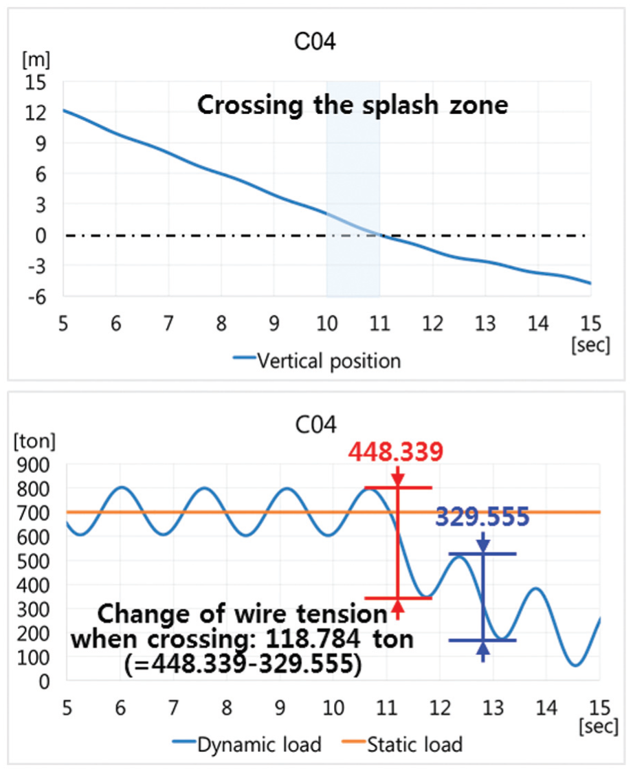
Change of wire tension of Case C04 when crossing.
Conclusion and future works
The lifting simulation when the OSV installs the offshore structure such as subsea equipment was performed in this study by varying operating conditions. Especially, when lifting off the structure, the excess of tension of wire ropes of the OSV crane and the collision between the OSV and the structure were assessed for given operating conditions such as ocean environmental loads and hoisting speed of the structure. That is, dynamic responses such as the motion, the wire tension, and the collision were calculated based on multibody system dynamics in this study. As a result, the maximum amplification factor of 1.050 was from the case in which the wave height is 1.5 m, the wave period is 9.0 s, the heading angle is 0°, and the hoisting speed of the equipment is 0.1 m/s. And there are some cases having the collision between the OSV and the equipment. And when lifting the structure in the air, the pendulum motion of the equipment was checked according to various ocean environmental loads. That is, maximum traveling distance of the structure was calculated with the wire tension. As a result, the maximum traveling distance of 1.960 m was from the case in which the wave height is 1.0 m, the wave period is 6.0 s, and the heading angle is 90°. Finally, when the structure penetrating the water surface, the varying buoyancy force and the slamming impact force were calculated by considering the position and the lowering speed of the equipment. And the wire tension was also calculated by considering these forces. As a result, it can be seen that the faster lowering speed is, the larger slamming impact force and the more rapid varying of buoyancy force are, which leads to the larger change of wire tension and the more rapid change of wire tension. From these simulations for the lifting method, including the steps of lifting off, lifting in the air, splash zone crossing, the operability of the method could be investigated at the given operating condition.
As future works, the improvement of this simulation will be made. First, the validation of simulation results will be made with some experiments or real operation data. And the simulation will be applied to more realistic examples. In addition, the way to quantify the sensitivity of the collisions to different operating conditions will be studied. A more refined method for estimating the slamming impact force will be studied. The simulation for other steps of the lifting operation such as deep submerging and landing will be performed.
Footnotes
Academic Editor: Chuanzeng Zhang
Declaration of conflicting interests
The author(s) declared no potential conflicts of interest with respect to the research, authorship, and/or publication of this article.
Funding
The author(s) disclosed receipt of the following financial support for the research, authorship, and/or publication of this article: This work was partially supported by (1) BK21 Plus, Education & Research Center for Offshore Plant Engineers (COPE) of Seoul National University, Republic of Korea, (2) Research Institute of Marine Systems Engineering of Seoul National University, Republic of Korea, and (3) Engineering Development Research Center (EDRC) funded by the Ministry of Trade, Industry & Energy (MOTIE), Republic of Korea.