
Abstract
Synchronized motion control with high accuracy becomes very essential part in industry. Due to some possible effect such as unknown disturbance or unmatched system model, it is difficult to obtain the precision of synchronous control using the conventional proportional–integral control method with parallel architecture. The adaptive compensator must be employed to eliminate tracking errors. The objective of this research is to propose the modified cross-coupling architecture using single-neuron proportional–integral controller and a synchronous compensator for dual-axis linear actuator. The single-neuron proportional–integral control strategy with delta learning algorithm can adjust the weighting coefficients of controllers to provide the robustness for each single-axis DC linear actuator system. A back-propagation neural network compensator is designed to adaptively reduce position and velocity errors between the two-axis servo systems. Both simulation and experimental results are developed to demonstrate that the synchronous position tracking performances in terms of root mean square error and sum of absolute error can be substantially improved, and the robustness to linear actuator uncertainties can be obtained as well. The proposed coupling strategy which uses the microchip platform and pulse–width modulation control technique is realized and implemented, and the synchronization performances to external disturbance load are illustrated by several experimental results.
Keywords
Introduction
Synchronized motion control of actuator has been applied in various applications such as precision machines, health care, and home appliances. 1 Since the control systems must have some aspects such as robustness, safety, and low-cost in maintenance, they can be obtained by conventional or modern control method that appropriate with the linear actuators. Linear actuators are used in machine tools, industrial machinery, and in many other places where linear motion is required. It is an important problem that the motion of multiple axes linear actuators must be controlled in a synchronous manner.2,3
Architectures of the synchronous motion control method 1 can be classified into four categories: (1) master–slave motion control, (2) cross-coupling technique (or synchronous master motion control), (3) bi-axial cross-coupled technique, and (4) relative dynamic stiffness motion control. In multi-axes synchronization motion control, the system performance depends more on the coordination of multiple motion actuators than on individual motion actuator. 4 A linear quadrature controller and an adaptive controller were used to synthesize the synchronization compensator. However, each axis of multiple motion actuator control has a separate closed-loop control, so that the control loop of one axis receives no information regarding the other. 5 Therefore, the individual actuator system needs a synchronous compensator to coordinate and eliminate different position errors among multiple actuators. The synchronization motion control can use coupling as synchronous compensator, which can be tackled by mechanical or control algorithm to compensate the effect of backlash, friction, and mechanical defects. The parallel synchronous control scheme6,7 is proposed to construct the coupled model for a gantry machine tool. The proportional–integral (PI) synchronous compensator is designed to verify the positioning accuracy. However, conventional control is inappropriate to tackle many problems such as steady-state error, speed changes, and load disturbances. Several advance intelligent control methods,7–9 such as fuzzy method, neural network (NN), and particle swarm optimization (PSO), are proposed. One of the proposed methods is tuning parameters of PI controller using NN. The objectives using NN are stability robustness, good tracking performance, and robustness against plant modeling uncertainty and environmental uncertainty.8–13 New methods for proportional–integral–derivative (PID) controller using single neuron 11 is proposed and tested in speed control system with DC servo motor. Furthermore, the single-neuron proportional–integral (SNPI) controller has properties such as self-learning, self-adaptive, and strong robustness. Moreover, the single neuron is a simple structure and a powerful tool in PI parameter optimization.
Due to the inherent behavior of each single-axis servo actuator, it is difficult to model the complicated nonlinear property of the synchronous error between dual-axis servo systems. For each DC feed actuator, the identification process is the first step to have an approximated system modeling. The adaptive SNPI controller is developed in single servo loop to improve the tracking performance and position accuracy. The proposed modified cross-coupling technique, which uses an additional synchronous controller to reflect the system mismatch and load variations, can eliminate the relative servo position error signal. A back-propagation neural network (BPNN) compensation controller is proposed, and the online learning rule is utilized to reduce the synchronous error between the two actuators. The BPNN regularizes input signals from synchronous position error and velocity error and generates output signal via the NNs, and the output signal as compensated force is fed to controller of each servo systems. The online learning rule minimizes the defined error using delta algorithm to adjust weighting of NN. The simulation and experiment results show that the proposed architecture can outperform parallel architecture in terms of better tracking performances.
This article is organized as follows: dynamic model of DC servo linear actuator is constructed in section “Dynamic model of DC servo linear actuator.” Design of synchronous architecture using NN is described in section “NN-based synchronous compensator.” SNPI controller is stated in section “Adaptive neuron controller.” Section “Simulation and experimental results” provides the simulation and experimental results. Finally, a brief conclusion is given in section “Conclusion.”
Dynamic model of DC servo linear actuator
The electric linear actuators can provide an easy way to mount and operate into an automated process. They offer advantages over mechanical and hydraulic system since their functions are self-contained, rugged, and making them ideal anywhere you want to lift, push, pull, and position a load. The linear actuator is composed of a DC motor, two gears, and ball screw, as shown in Figure 1. A traveler on the ball screw is forced either toward or away from the motor, essentially converting the rotating motion to a linear motion. It is desired to have an application need for synchronous motion for coordinated moves and precise control of position, velocity, and acceleration. The synchronous operations of multiple actuators are widely used in patient lifts or beds, handicap adapted vehicles, conveyor belts, and door controlling.

The mechanism of DC motor and linear actuator system.
Mathematical model of linear actuator is derived by developing equation between the motor and components of the feed drive system. Several researches6,14 on the dynamic model of ball screw stage with DC motor have been conducted. The system block diagram for single-axis DC servo linear actuator is depicted in Figure 2. For the input signal is the reference voltage


where

Block diagram of linear actuator.
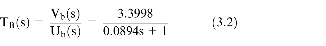
In general, DC motor has a high speed and low torque, but a linear actuator needs high torque with low speed to drive load. To obtain the high torque, precision velocity, and position, the contact mechanism using gear is employed between DC servos and linear actuator. Transfer function of the feed drive system between the voltage command and the actuator velocity

Table 1 shows the specification of DC linear actuator. The control method performed by the actuator is by means of pulse–width modulation (PWM) control driven by an H-bridge module. Since the overall drive system has nonlinear effects such as saturation, dead zone, friction, and backlash effects, it is difficult to identify an accurate electromechanical system model. The MATLAB System Identification Toolbox 15 is used to obtain the approximated system transfer function for each axis. The identification process shown in Figure 3 is applied to construct the transfer function. It is equipped with dsPIC30 microcontroller (MCU), H-bridge drive circuit, digital input–output (I/O) interface card, and a personal computer. The duty cycle of the pulse generated by peripheral interface controller (PIC) MCU is programmable and can be set at 50%, 70%, and 100%. Figure 4(a) and (b) shows time-domain velocity responses with different duty cycles for A- and B-axis actuators, respectively. The input PWM command and output rotation speed data are measured and collected. The properties of linear parametric models and first-order model are selected in the identification toolbox. From the measurement results, it is confirmed that the system models can be obtained. For simplification, the first-order transfer functions can be approximated and used to describe the two-axis system

where
Specification of the DC linear actuator.


System identification architecture.

The velocity measurements for (a) A-axis actuator system and (b) B-axis actuator system, for 100%, 70%, and 50% duty cycle.
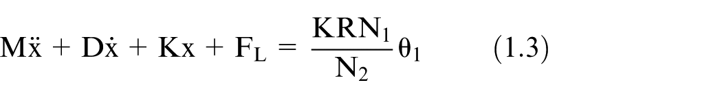
In practical applications, the DC actuator model varies when the drive system operates under different conditions. The mathematical dynamic model in equation (1.3) can be expressed as

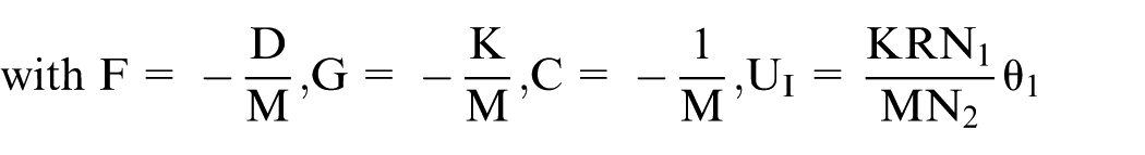
By considering the parameter variations and load disturbance, the system dynamics is considered as
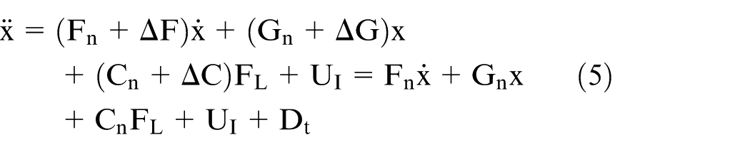

where
NN-based synchronous compensator
The synchronized motion control method can be divided into some categories.1,6 The framework of synchronous master motion control is illustrated in Figure 5. It is also called the parallel synchronous control architecture. In this system, the SNPI controller is utilized in position and velocity feedback loops to perform a precision control of position. It includes the master command generator scheme, and each axis is driven separately and independently. The SNPI controller with the characteristics of adaptive and online adjustment can replace conventional PI controller to improve performance of motion control. Thus, it does not have synchronous compensator between two actuators, and the synchronization error cannot be corrected by each other.
The parallel architecture with SNPI controller.
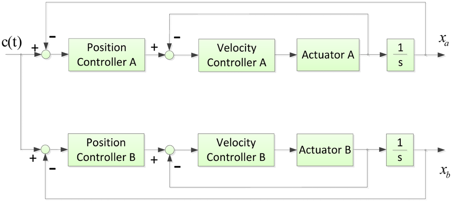
To improve the performance of system, cross coupling1,3,6 has been applied between actuator A and actuator B in SNPI controller methods. In this research, the modified cross-coupling technique is designed as shown in Figure 6. An additional feedback signal generated by the relative position signal between two subsystems is employed. This arrangement can reflect any load variations and system uncertainty presented in both subsystems by the applied extra signal. The synchronous compensator that used an adaptive neuron control is developed in the modified cross-coupling structure to eliminate the synchronization error.

(a) The proposed modified cross-coupling architecture with SNPI and BPNN compensators and (b) the design flowchart of the network learning rate in our proposed system.
A three-layer feedforward NN is implemented in our BPNN controller, as shown in Figure 7. Due to the different position responses of the two axes, the tracking error can be derived by the position error and the velocity error. The two synchronization errors are the input variables of NN and defined as the input vector

where

where

where

where

where

where
where

and


Adaptive back-propagation neural network controller structure.
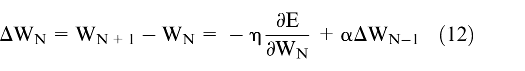
The gradient of
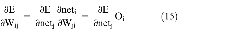
and
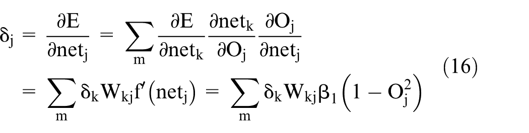
It is difficult to calculate the Jacobian

where
Adaptive neuron controller
P/PI controller and stability analysis
A better control system is developed to provide good characteristics such as stable, simple structures, good tracking performance, and easy to design without the need for heavy computational complexity. One better control structure is to include a velocity loop inside a position loop for position control. Often, the velocity loop uses PI control, and the position loop applies P control structure. It is usually called the P/PI control.17,18 Traditionally, the PI velocity loop is tuned for maximum performance, omitting high-frequency effects due to the feedback velocity signal formed by differentiating a sampled position signal. The design of the controllers for the position loop and velocity loop in S-domain is expressed as


where
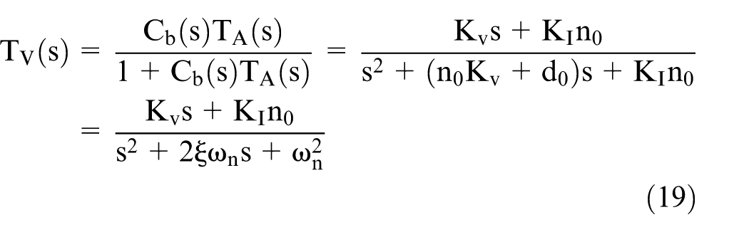
where
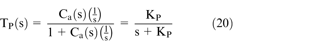
The pole of the position loop is also in the left half plane, so the feedback loop is stable. The stability of the proposed P/PI control method is guaranteed as the P gain and integral gain are >0.
Adaptive single-neuron controller
Figure 8(a) shows the single-axis position control loop. The feedback loop included the position controller and velocity controller in digital form is given by


where

(a) Block diagram of the traditional single-axis position control loop and (b) the proposed structure of SNPI controller.
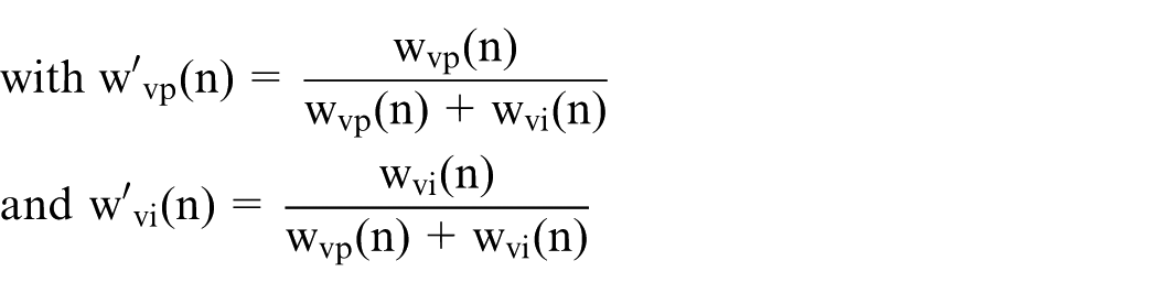
The common structure for high-performance electric motor is to enclose a cascaded velocity loop within a position loop. Using the traditional P/PI control, the control gains are fixed and cannot be changed during the overall control process. The uncertainty, such as parameter variations, varying load, friction, and dead zone, is not taken into consideration. To deal with these uncertainties, adaptive SNPI controller with self-adapting and self-learning abilities is employed to replace the PI controller and improve the tracking performances. The SNPI controller is designed and evaluated to retain the desired performance automatically in many dynamic systems.11,19,20 An adaptive SNPI control system is represented by the block diagram in Figure 8(b). In our architecture, a single-neuron P controller is designed in the position loop, and an SNPI controller is developed in the velocity loop. It offers better learning ability and ensures that the system can track the trajectory under external disturbances. The complete structure of the SNPI controller can be expressed by

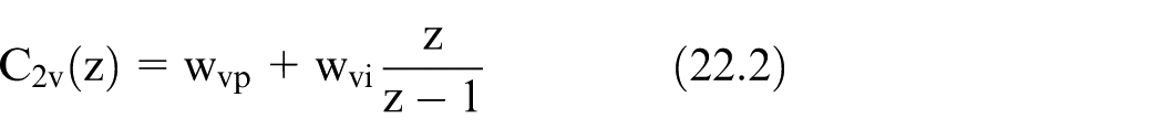
where


where

where


where


where

where
Simulation and experimental results
In this section, simulation results and experimental results are provided to verify the effectiveness of our proposed control methods. In the simulation and experiment, two architectures are conducted to evaluate the performances of the proposed control system. Two architectures, (1) the parallel architecture with SNPI method and (2) the modified cross-coupling architecture with SNPI controller and adaptive BPNN synchronous compensator, are shown in Figures 5 and 6, respectively.
The BPNN compensation architecture for dual-axis linear actuator is simulated to demonstrate the synchronization performance. To measure the control performance of the proposed control system, the root mean square error (RMSE) and sum of absolute error (SAE) for the synchronized tracking are employed. These are defined as follows:
RMSE. The metric adopted to verify the tracking error performance is the RMSE, which makes an excellent general-purpose error metric. This is defined and given by

where
2. SAE. The SAE metric can be the second indicator to decide the control system performance. It is defined as

The control objective is to control the position of the two-axis linear actuator to track the reference position profile with minimum tracking error using the proposed adaptive BPNN compensator under different load conditions.
Simulation results
In the simulation, MATLAB or Simulink toolbox is applied to simulate and design of dual-axis linear actuators. The system models of actuator A and actuator B are obtained from the system identification architecture in Figure 5. The transfer functions are approximated and described in equations (3.1) and (3.2). In BPNN synchronous compensator, the number of node in the hidden layer is selected as 5, the learning rate
The learning rate of the NN is obtained using the optimization of the metrics RMSE and SAE. The synaptic weights of single-neuron P/PI controllers are optimized with respect to the position tracking error for each A-axis and B-axis models. The learning rate parameters of the single-neuron controllers are selected as follows:
A-axis and B-axis

Then, the RMSE and SAE performance metrics are applied for the BPNN compensator optimization. The parameters
The comparisons of simulation results between SNPI controller in parallel architecture and SNPI controller using synchronous compensator under zero disturbance condition can be described in Figure 9(a). The trajectory is a step reference input, and the displacement moves to 200 mm as the time equal to zero. As can be seen, the tracking error of synchronous compensation scheme is lower than that of parallel architecture. Figure 9(b) shows the simulation result of synchronization error under nonzero disturbances. The equivalent load disturbance with
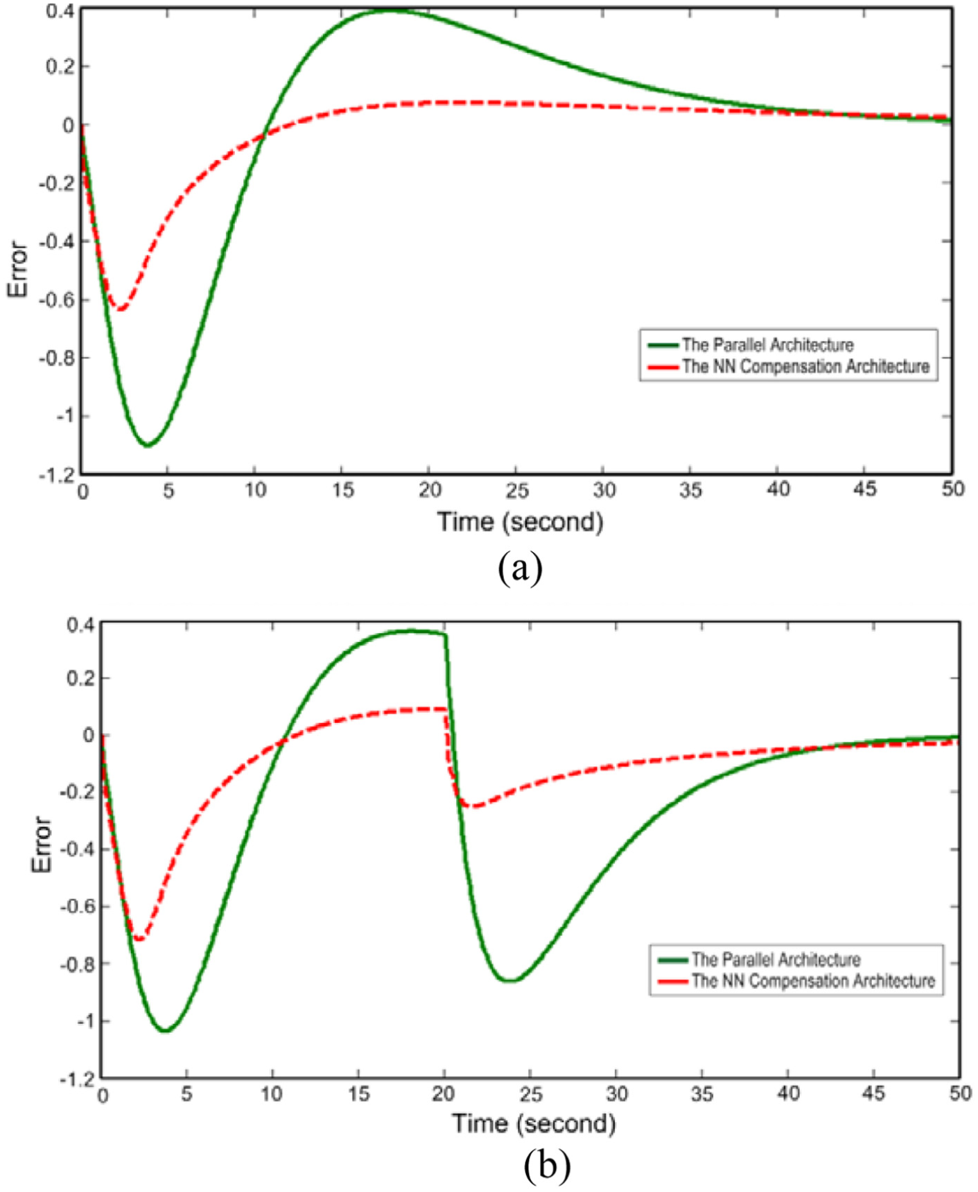
Simulation results of (a) the synchronization error under zero disturbance condition and (b) the synchronization error under the equivalent disturbance

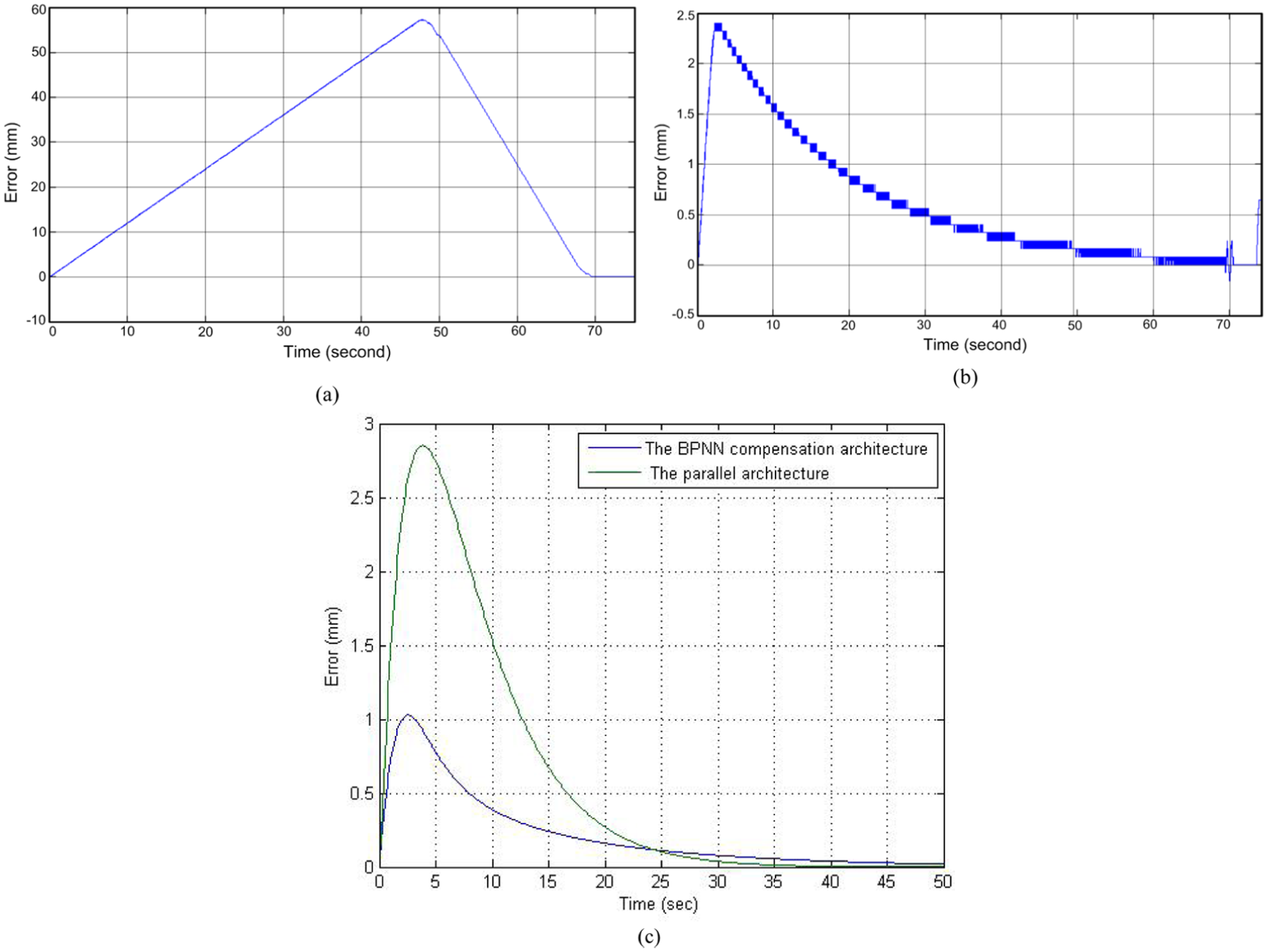
Simulation results of ramp input signal: (a) position response of parallel architecture with nonzero disturbance, (b) position response of the modified cross-coupling BPNN compensation architecture with nonzero disturbance, and (c) the synchronization error comparisons.
Simulation results of synchronization error.

SNPI: single-neuron proportional–integral; BPNN: back-propagation neural network; RMSE: root mean square error; SAE: sum of absolute error.
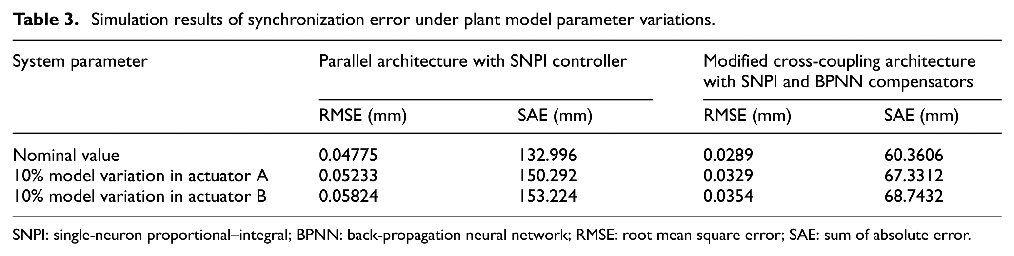
In addition, the effect of the system model variation is considered to present the dynamic response of our proposed method. The 10% parameter difference of the nominal plant model is studied for the A-axis and B-axis actuators, respectively. Table 3 shows the performances of the synchronization errors in terms of RMSE and SAE values. It can be seen that our proposed architecture with SNPI and BPNN compensators achieves the better synchronization capability and outperforms the conventional method. On average, the proposed architecture offers the 0.02037-mm reduction in RMSE and 80.0257-mm reduction in SAE compared with the traditional method.
Simulation results of synchronization error under plant model parameter variations.
SNPI: single-neuron proportional–integral; BPNN: back-propagation neural network; RMSE: root mean square error; SAE: sum of absolute error.
Experimental results
Experiments are performed to verify the results obtained from the simulations. The experimental setup is composed of the dsPIC30f4011 MCU board, the MOSFET driver A3941 module, the two-axis linear actuators, and the development system using personal computer. The experimental setup of dual-axis linear actuators is illustrated in Figure 11. The dsPIC30F device family employs a powerful 16-bit architecture that integrates the control feature of an MCU with the computational capabilities of a digital signal processor (DSP). In the MCU resources, the PWM module, universal asynchronous receiver–transmitter (UART) module, and quadrature encoder interface (QEI) are used in our system. This research demonstrates the tracking performance of SNPI controller and BPNN compensator which are experimentally implemented in dsPIC30F4011 MCU using C language. Figure 12 shows the block diagram of the hardware experiment setup. All the C language codes are developed using MPLAB IDE in the personal computer (PC) Windows environment and then downloaded to the Flash ROM. In the main function, all the parameters and digital I/O initialization, such as UART, PWM, and QEI function, are arranged first. The interrupt service routine (ISR) is designed using 1-ms sample period to connect with QEI for position feedback. The ISR program can compute the tracking position error and velocity error and generate the PWM commands to A3941 module according to the proposed control algorithm. The control algorithm implemented in MCU includes (1) BPNN compensator, (2) single-neuron P controller for the position loop, and (3) SNPI controller for the velocity loop. The A3941 drive module is a full-bridge control circuit which includes the external N-channel power MOSFETs. This application module is specifically designed for automotive applications with high-power inductive motors and brush DC motors. Figure 13 shows the H-bridge circuit using A3941 module. The A3941 can be driven with a single PWM input from the dsPIC MCU, and four low-voltage level digital inputs can provide control for the gate drives. Pulse width modulation high (PWMH) and pulse width modulation low (PWML) pins can be used to control current in the power bridge. PHASE pin can determine the positive direction of load current. Synchronous rectification (SR) pin enables or disables synchronous rectification.

The experimental setup.

Blok diagram of the hardware experiment setup.

The H-bridge circuit using A3941 module.
In the experiments, the C language program is designed in dsPIC30 MCU to demonstrate the performance of dual-axis linear actuators. In BPNN compensator, the number of node in the hidden layer is selected as 5, the learning rate
A-axis and B-axis

In this experiment, the PWM frequency is set as 1 kHz, and the stroke of linear actuators is 200 mm. The sampling frequency is 1 kHz measured from the Hall sensor built in the servo mechanism. The velocity feedback signal is formed by differentiating a sampled position signal. It is obtained and calculated by dsPIC MCU with the sample frequency of 1 kHz. The sampling frequencies for current, velocity, and position loop are designed as 1 kHz, 200 Hz, and 100 Hz, respectively. We have built and tested the speed sensor in the proposed control system. The speed information is calculated by differentiating a sampled position data from Hall sensor. The velocity control loop is tested by downsampling the original sampling frequency of 1 kHz. The minimum speed measurement is 200 Hz in our experiment setup. These designed parameters are developed and tested in our system.
Based on the plant model obtained from system identification, simulation results are conducted and demonstrated in Figure 14(a) and (b) for the parallel architecture and the synchronous compensator architecture, respectively. Figure 14(c) and (d) shows the experimental results of position responses of actuator A and actuator B with these two structures. In this study, the ramp reference input is used to verify the control performance of our proposed method. The desired output position moves from 0 to 220 mm with a maximum velocity of 3.5 mm/s. Figure 15(a) and (b) shows the transient responses of synchronization errors. Clearly, the transient synchronization error of compensation architecture is significantly lower than that of parallel architecture. As can be seen, the synchronous error is always within 1.6 mm for our method. Figure 15(c) shows the simulation results corresponding to the experiment results above. The structure that utilized the approximated plant model from system identification can offer a better reference design for practical system. Using the parameter adjusting mechanism, the adaptive compensator improves the transient and steady-state performance, and the position response error can be reduced well.

(a) Simulation results of position response with the parallel architecture, (b) simulation results of position response with the proposed modified cross-coupling architecture, (c) experimental results of position response with the parallel architecture, and (d) experimental results of position response with the proposed modified cross-coupling architecture.

(a) Experimental results of synchronization error of parallel architecture, (b) experimental results of synchronization error of the modified cross-coupling architecture with BPNN compensator, and (c) simulation results of synchronization error for the parallel architecture and BPNN compensator with zero disturbance.
The simulation and experimental results are provided to further demonstrate the robustness of the proposed control system under the external disturbance. The equivalent external disturbance condition is

(a) Simulation results of position response of the parallel architecture with nonzero disturbance, (b) simulation results of position response of the proposed modified cross-coupling architecture with nonzero disturbance, (c) experimental results of position response of parallel architecture with nonzero disturbance, and (d) experimental results position response of the modified cross-coupling architecture with nonzero disturbance.
Experimental results of (a) synchronization error of parallel architecture with nonzero disturbance, (b) synchronization error of the modified cross-coupling architecture with nonzero disturbance, and (c) the simulation results of synchronization errors for parallel architecture and modified cross-coupling architecture.
Experimental results of synchronization error.

SNPI: single-neuron proportional–integral; BPNN: back-propagation neural network; RMSE: root mean square error; SAE: sum of absolute error.
Conclusion
This article presents the adaptive NN-based synchronization architecture for dual-axis linear actuator system. An integrated model of DC motor drive system including mechanical ball screw subsystem is derived to represent the motion dynamics of control system. The novel single-neuron architecture with simple structure and better approximation property is applied for P/PI controllers to improve the tracking performance of the single-axis position and velocity control loops. The BPNN synchronous compensator can be online trained effectively and adaptively to compensate the synchronization error between the master and slave actuators. An accurate identification process of electrical and mechanical system has been conducted to verify the effectiveness of the proposed architecture in simulation design. The new SNPI controller and BPNN compensator are implemented and built in a dsPIC30 MCU to evaluate the tracking performances. From the theoretical and experiment results, the control performances in terms of RMSE and SAE are well achieved, and synchronization accuracy is much improved. Also, our proposed method with adaptive learning algorithm is a feasible solution in practical implementation.
Footnotes
Academic Editor: Stephen D Prior
Declaration of conflicting interests
The author(s) declared no potential conflicts of interest with respect to the research, authorship, and/or publication of this article.
Funding
The authors would like to thank the Ministry of Science and Technology of the Republic of China, Taiwan, for financially supporting this research under Contract No. MOST 105-2622-E-224-010 -CC3, MOST 104-2622-E-224-016-CC3, and MOST 104-2218-E-224-002.