
Abstract
A new polynomial fitting model based on a neural network is presented to characterize the hysteresis in piezoelectric actuators. As hysteresis is multi-valued mapping, and traditional neural networks can only solve one-to-one mapping, a hysteresis mathematical model is proposed to expand the input of the neural network by converting the multi-valued into one-to-one mapping. Experiments were performed under designed excitation with different driven voltage amplitudes to obtain the parameters of the model using the polynomial fitting method. The simulation results were in good accordance with the measured data and demonstrate the precision with which the model can predict the hysteresis. Based on the proposed model, a single-neuron adaptive proportional–integral–derivative controller combined with a feedforward loop is designed to correct the errors induced by the hysteresis in the piezoelectric actuator. The results demonstrate superior tracking performance, which validates the practicability and effectiveness of the presented approach.
Keywords
Introduction
Piezoelectric (PZT) ceramic actuators are extensively used in ultra-high precision and tracking mechanisms and offer the advantage of simple construction, fast response, rapid dynamic performance, and limited thermal expansion in driven processes. 1 However, the inherent characteristics of these actuators, that is, nonlinearity and hysteresis, adversely affect the tracking precision. An example is found in scanning tunneling microscopes, in which a PZT actuator is often used as a precision moving unit; however, the hysteresis nonlinear characteristic introduces an error into the precision positioning. Hysteresis may even cause system instability in some applications.2–7
Model control for the hysteresis of PZTs has been studied for decades; currently, the main modeling methods are those of Preisach, Prandtl–Ishlinskii (PI), Maxwell, Duhem, and Bouc–Wen and those based on polar coordinates and neural networks (NNs). 8 However, these methods continue to remain problematic in various ways. For example, the Preisach model and feedforward compensation method have been widely applied in open-loop control systems, but the computational cost is enormous and the derivation of the inverse model is relatively complex. 9 The structure of the PI hysteresis model is simpler than that of the Preisach model, but the modeling process is quite complicated as a result of the integrating element.10,11 The Bouc–Wen model has the feature of computational simplicity as only one nonlinear differential equation is demanded; however, the symmetric structure of this model limits its modeling accuracy.12–14
NN techniques have developed rapidly;15–18 research works involving the use of NNs for the modeling/correction of hysteresis have been published.19–22 Deng and Tan 19 created an expanded input field of hysteresis for one-to-one mapping conversion by using a hysteretic operator and then used a NARMAX model to describe the hysteresis in PZT actuators. One new NARMAX model based on a back-propagation (BP) NN was proposed to model the nonlinear hysteresis in PZT actuators, and a linear controller based on adaptive inverse control was designed for the correction of hysteresis in PZT actuators. 16 An adaptive NN-based controller for PZT actuators with unknown hysteresis was proposed. 17 An augmented feedforward multi-layer perceptron (MLP) was applied to describe a complex piecewise continuous undetermined nonlinear phenomenon for solving the differential equation of the Duhem model. Families of black box models based on pseudolinear and NNs were used to identify a PZT actuator for vibration-assisted drilling. 18
This paper proposed a NN modeling based on polynomial fitting to describe the hysteresis behavior of the PZT. Considering the input and output of the polynomial mathematics modeling as the input of NN, one-to-one mapping NN model is consequently established; this method overcomes the complexity of segmentation modeling of the traditional modeling method. Based on this model, single-neuron proportional–integral–derivative (PID) control with feedforward is used, and the maximum hysteresis error (MHE) is reduced from 18.12% to 1.29% with this compound control.
NN modeling of actuator
Hysteresis measurement of PZT actuators
The experimental platform shown in Figure 1 was established to analyze the hysteresis of PZT actuators. The platform was installed on an optical table for vibration isolation. The PZT actuator that was used is model AE0505D16F from Thorlabs. The actuator has a nominal displacement value of 0–17.4 µm under an input voltage of 0–800 V. The actuator is driven by a voltage source with a resolution of 0.01 V from 0 to 150 V. A heterodyne laser interferometer with 0.31 nm resolution (ZYGO-ZMI2000) was used to measure the displacement. The interference signal was acquired by a Zygo ZMI data acquisition system. The real displacement value was recorded and displayed in a LabView interface.
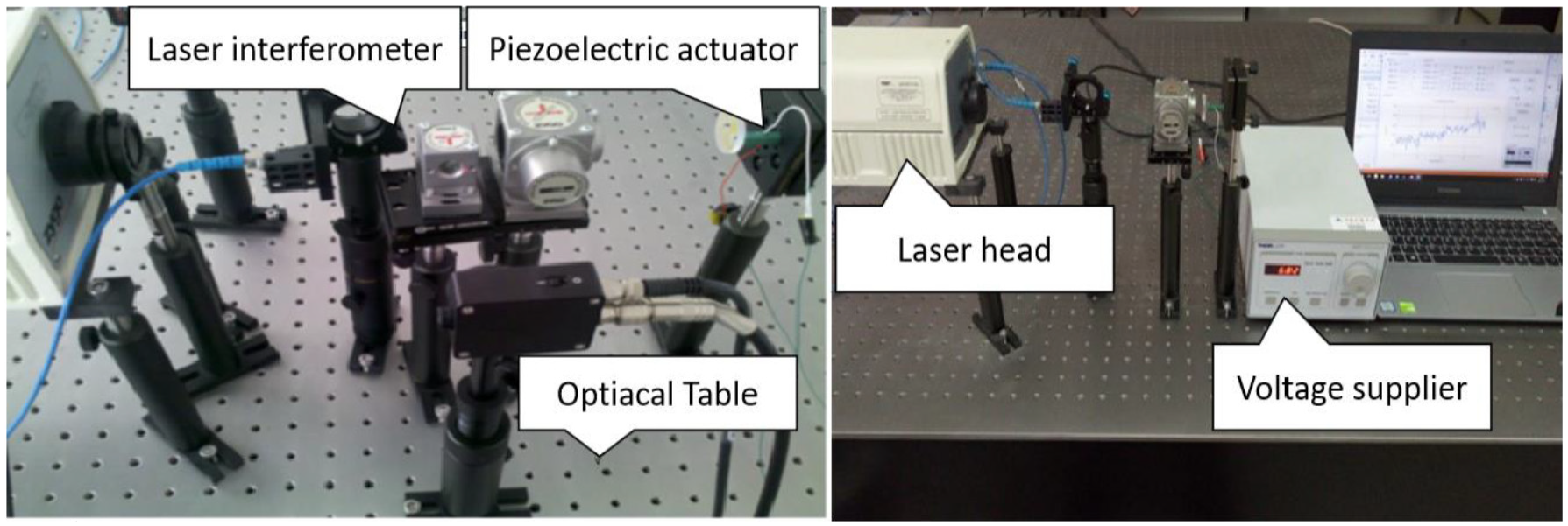
Experimental setup.
The hysteresis behavior of the PZT actuator is measured by driving the actuator by triangular wave voltage with changed amplitude. The approach we followed was to increase the amplitude from 0 to 60 V, after which it was decreased from 60 to 0 V in steps of 1 V. The sequential driven voltage signal has the same frequency and variation as the previous one except that the amplitude is 30 V. The displacement curve shown in Figure 2 is obtained by the LabView data acquisition program. The acquisition is performed every 0.5 s with 60 repetitions under each driven voltage. This is repeated for the next driven voltage until the entire voltage range is covered.
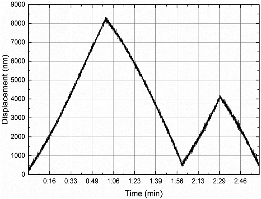
Displacement curve of piezoelectric actuator.
Averaging the displacement value under each driven voltage enables us to obtain voltage–displacement data pairs. Thus, the hysteresis is detected in the PZT actuator (the hysteresis curve is shown in Figure 3). To represent the hysteresis characteristics of the PZT actuators, the definition-MHE is given. The MHEs of major-loop and minor-loop hysteresis nonlinearity are 1049.48 and 367.33 nm, respectively.
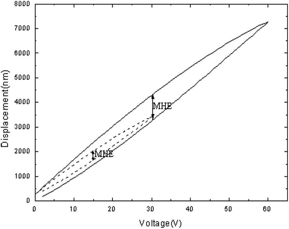
Experimental hysteresis curve in a piezoelectric actuator: the straight and dashed curves are the major loop and minor loop, respectively.
Polynomial fitting NN model of hysteresis
Artificial NNs have the property of self-learning, robustness, associative storage, and fault-tolerance. Classical BP NNs have been extensively used in industry due to their straightforward structure and practicality. A modified BPNN is proposed in this paper to identify the hysteresis of PZT actuators. 23
The inherent hysteresis nonlinearity of a PZT device is a multi-valued mapping relationship, whereas the classical modeling method can only process one-to-one mapping. An expansion input space is needed to model hysteresis in PZT actuators. A polynomial fitting model for hysteresis is constructed by considering the driven voltage u and the output d of polynomial equation as the input of the NN, with the actual displacement d′ being the output.
The equation of an ellipse is used for curve-fitting of the hysteresis.

where u is the driven voltage and d is the actual displacement.
The results for equation (1) are shown in equations (2) and (3), respectively, corresponding to the ascending and the descending curves of the major loop by using Matlab


where
As is shown in Figure 3, the data pairs are obtained by conducting experiments in the range 0–60 and 60–0 V driven voltage. Polynomial fitting is carried out for the major hysteretic loop, thus the undetermined coefficients


As the minor hysteretic loop is quite similar to the major one, the linear recurrence method is used to model the minor hysteretic loop, with equations (6) and (7) being the mathematical approach for the ascending and descending curves of the minor hysteretic loop, respectively
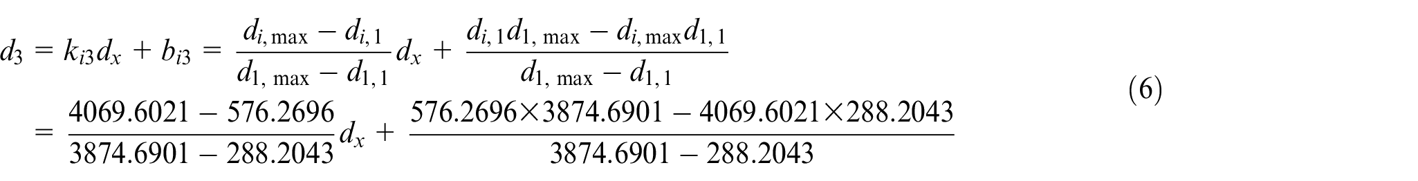
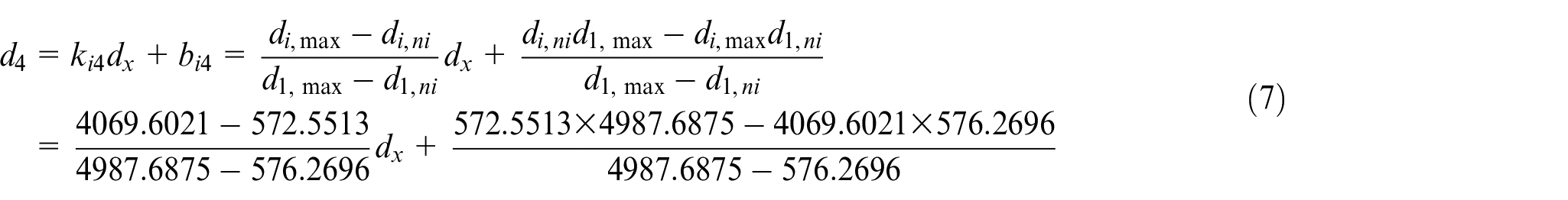
where
The output (d′) and the input (d, u) of the NN model should first be normalized, and then the normalized data should be divided into odd number group and even number group. The odd number group is used to construct hysteresis NN, while even number group is applied to test the generalization capability of the hysteresis NN model. A three-layer BP NN is used, and the structure is shown in Figure 4. We use trial-and-error solution to determine the number of neurons in the hidden layer of BP NN. The error of the training goal is set to 0.002. The number of neurons in the hidden layer was varied from 4 to 7. Eventually, the number was chosen as 6 because it enables the training error to converge to a minimum value of 0.0019.
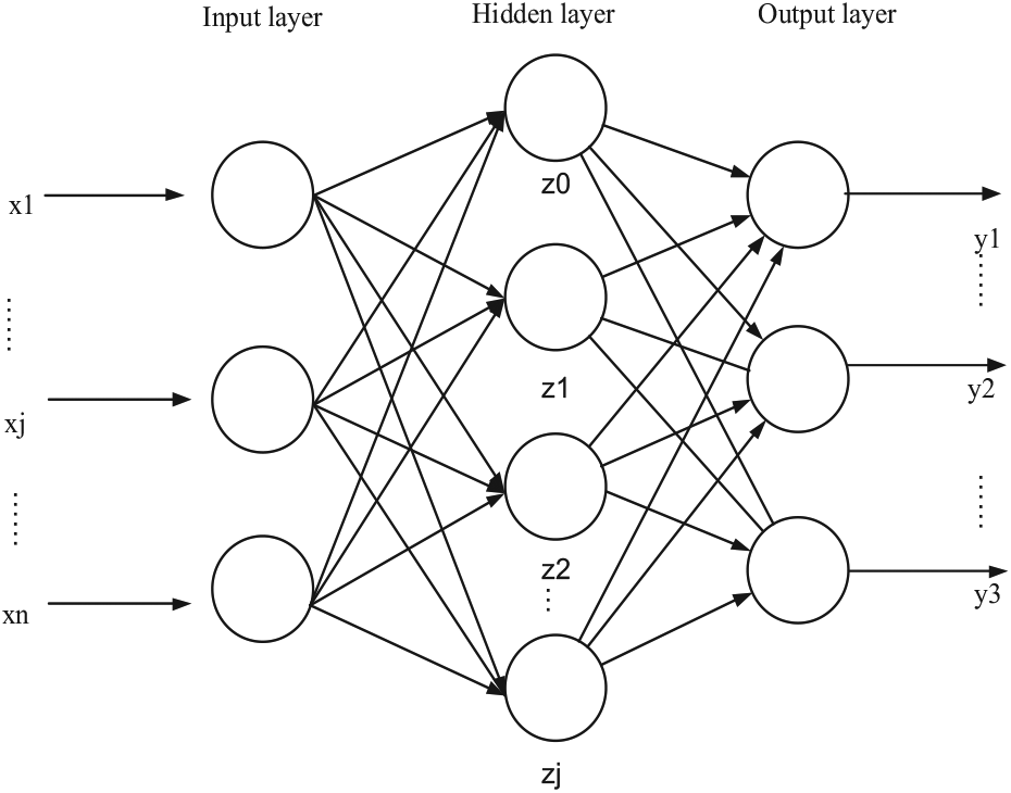
The structure of three-layer BP neural network. 24
Figure 5(a) represents the NN identification results. The identification errors are shown in Figure 5(b). The modeling error is within 300 nm and the average relative error is 1.42%.
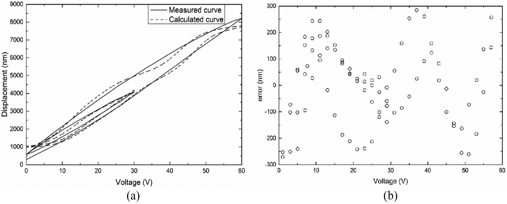
(a) NN identification results and (b) NN identification errors.
The even number group is applied to test the generalization capability of the hysteresis model. Figure 6(a) represents the NN test results. The test errors are shown in Figure 6(b). The error is within 400 nm and the average relative error is 1.45%
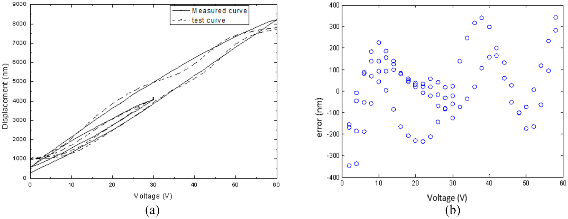
(a) NN test results and (b) NN test errors.
Controller structure design
Combined feedforward and feedback PID control
In respect that the performance of the feedforward controller is limited by the accuracy of the proposed hysteresis model, the PID feedback controller is used. The feedforward output is added to the PID controller output voltage and then sent to the PZT actuator. The diagram of combined feedforward and feedback PID control is shown in Figure 7. The output for the combined controller is
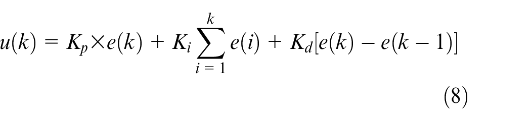
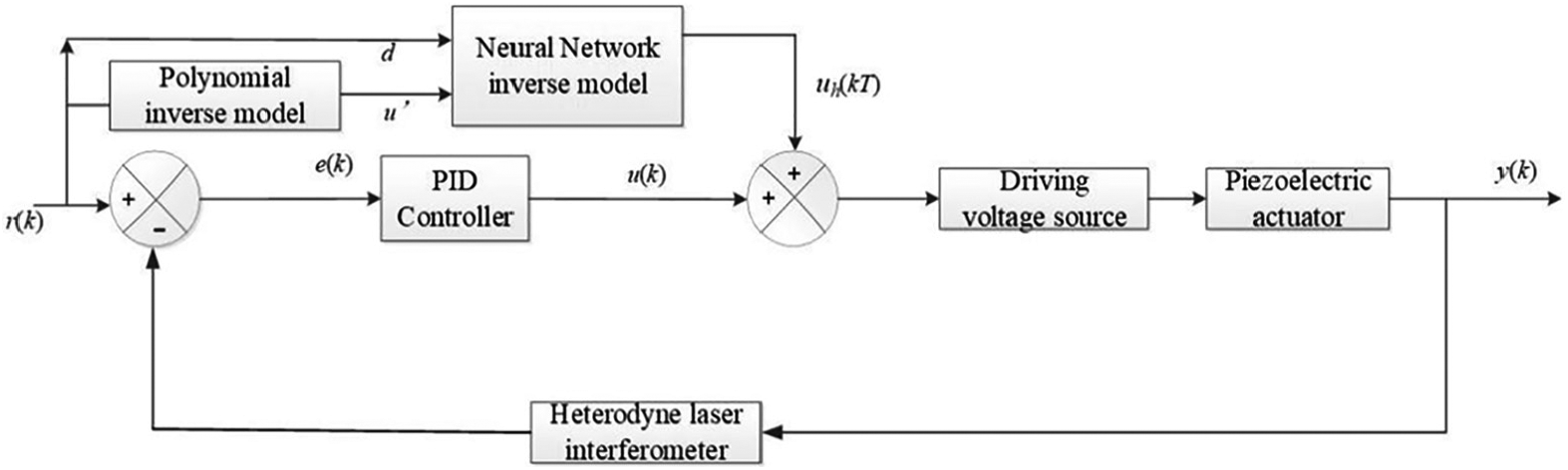
Block diagram of the combined feedforward and feedback PID control.
The NN inverse model is required for feedback control. The hysteresis polynomial mathematical model is expressed by equations (4) and (5) for the main loop and equations (6) and (7) for the minor loop. The NN inverse model is obtained by the inversion calculation of them. Equations (9) and (10) are the hysteresis inverse model for the main loop, and equations (11) and (12) are that for the minor loop


Combined feedforward and single-neuron adaptive PID control
Considering the complexity of the hysteresis of the PZT, the PID parameters are difficult to determine, a single-neuron adaptive PID controller benefits from both the self-adaptive and self-organization of NN and the simplicity and stability of PID controller is designed. The input of the neuron adaptive PID controller is the desired displacement of the PZT actuator, and the output is the driven voltage. The error is obtained from the difference between the actual displacement and the desired displacement and then is fed back to the adaptive algorithm for adjusting the controller.
The control structure of the single-neuron adaptive PID controller combined with feedforward is shown in Figure 8. The three input values of the neurons are
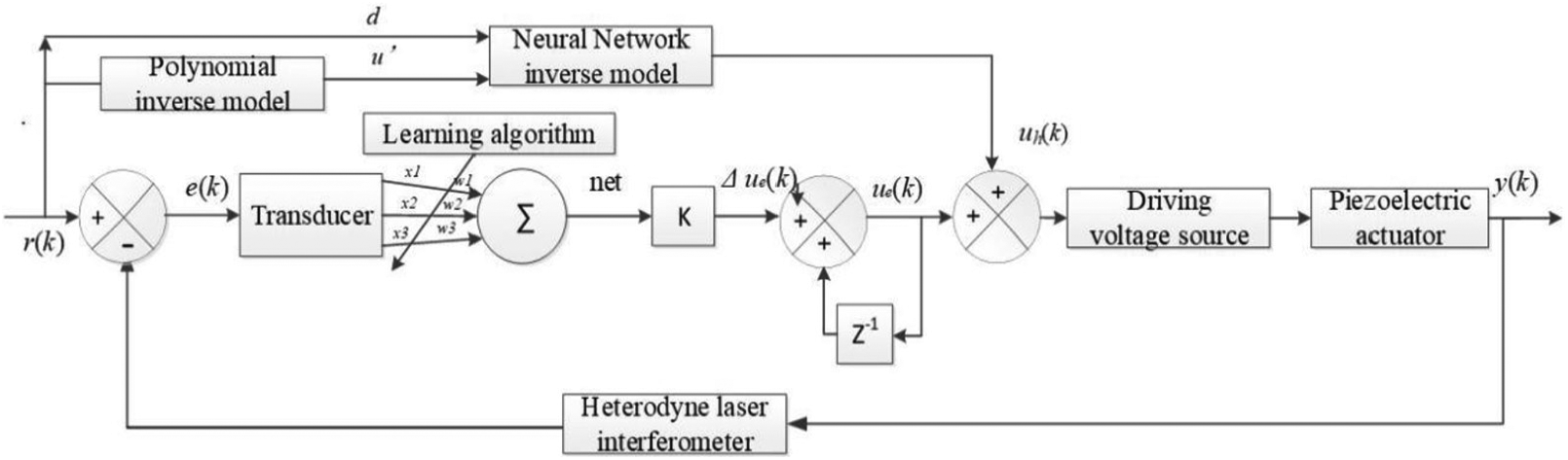
Structure of the combined feedforward and single-neuron adaptive PID control.
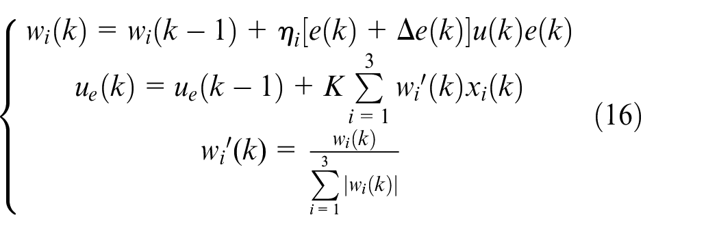
The neuron PID controller uses Hebb’s supervised learning rule. The weight value is adjusted according to the output error, which is shown in equation (13), where

The output of the single-neuron PID controller is
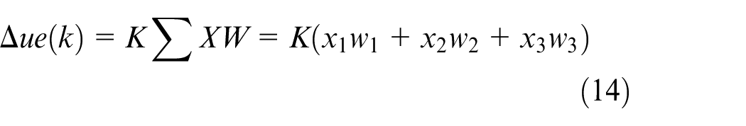
From equations (13) and (14), we know that the inputs of the single-neuron PID controller are connected with the output error

Studies on PID controller online regulation have shown that the weight value, which varies with the environment, is mainly related to
The method whereby the weight value is set is obtained according to the aforementioned derivation, and this method combined with the traditional PID closed loop is used to obtain the single-neuron PID controller.
Experimental procedures and results
The experimental platform that was used to verify the proposed NN model and the developed controller is shown in Figure 1. The driving voltage source that was used is model BPC301 from Thorlabs. The developed control algorithm was realized using C# language. We compare the control performance of the two control method in the following section.
Feedforward and PID feedback compound control
The PZT displacement with feedforward and PID feedback compound control was executed by acquiring the displacement value every 0.5 s with 60 repetitions under each driven voltage. The experimental results are shown in Figure 9. The displacement curves and input–output relation curves are shown in Figure 9(a) and (b).
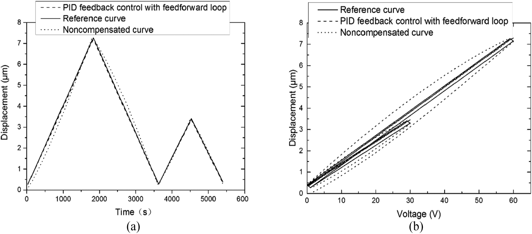
Experimental hysteresis curve with feedforward and PID feedback compound control: (a) displacement curves and (b) input–output relation curves.
We can see from Figure 9 that the nonlinearity of the hysteresis is diminished by this controller. The MHE of the major loop was reduced from 1049.48 to 85.67 nm, whereas that of the minor loop was decreased from 367.33 to 52.65 nm.
Feedforward and single-neuron adaptive PID feedback compound control
The same driven voltage signal was used to test the performance of the single-neuron adaptive PID control with feedforward loop. The experimental results are shown in Figure 10.
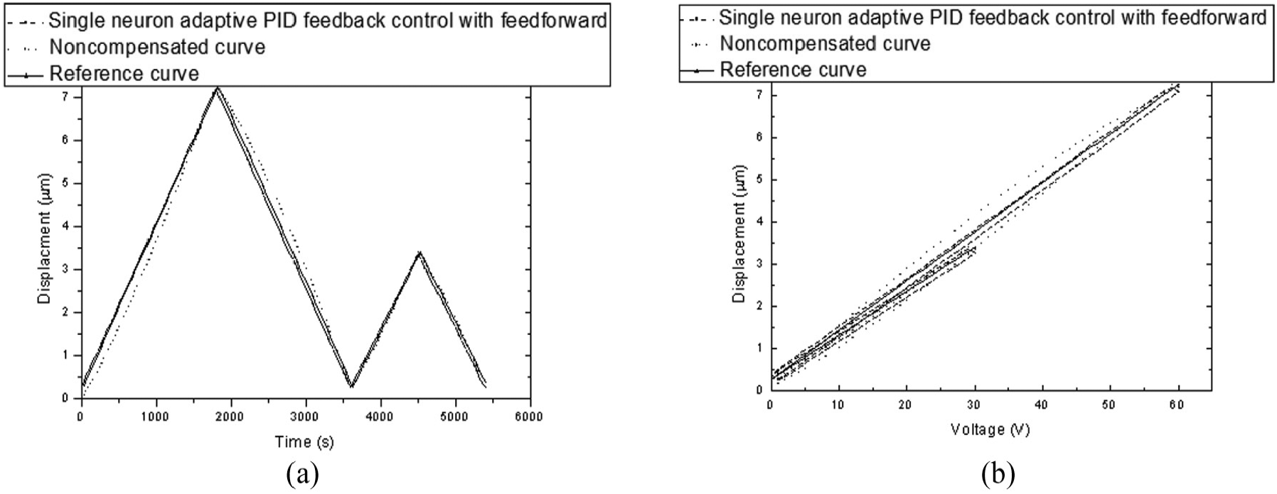
Experimental hysteresis curve with feedforward and single-neuron adaptive PID feedback compound control: (a) displacement curves and (b) input–output relation curves.
The experimental results in Figure 10 indicate that the tracking errors caused by both the major-loop and minor-loop hysteretic nonlinearities are significantly restrained. The MHE of the major loop was reduced to 37.61 nm, whereas that of the minor loop was decreased to 42.46 nm.
The tracking control performance between single neuron adaptive PID feedback tracking with feedforward loop and PID feedback tracking with feedforward loop was further compared by conducting tests using a triangular wave reference signal with an amplitude of 60 V in intervals of 1 V. The acquisition was performed every 0.5 s with 20 repetitions under each driven voltage. Figure 11 shows the tracking results. The maximum tracking error was less than 306.90 nm with single-neuron adaptive PID control, whereas it was less than 333.36 nm with feedback PID control.
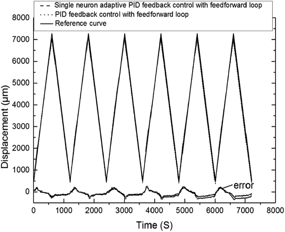
Comparison of two different control loop tracking of a triangle wave.
The results obtained for the comparison of this two different control loop are listed in Table 1.
Comparison of feedforward combined with PID compound control and feedforward combined with single-neuron adaptive PID control.
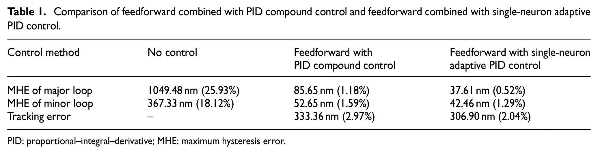
PID: proportional–integral–derivative; MHE: maximum hysteresis error.
It is evident from Table 1 that the tracking accuracy using single-neuron adaptive PID feedback and feedforward compound control is significantly improved.
Finally, an experiment was conducted to demonstrate the step displacement using the single-neuron adaptive PID feedback and feedforward compound control. The driven voltage was increased from 0 to 60 V and then decreased from 60 to 0 V in increments/decrements of 10 V every 10 s. The back and forth displacement of the PZT actuator was measured. As shown in Figure 12, the actuator can return to its initial position correctly with this compound controller. If we note
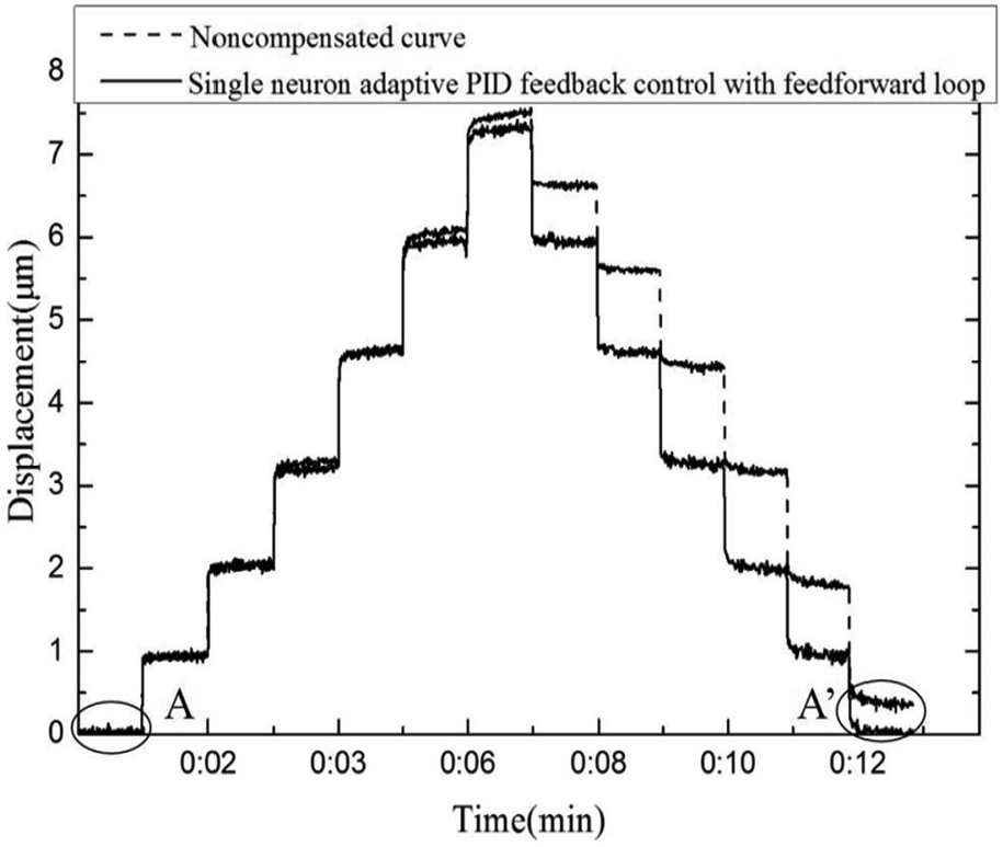
Experimental result of a back and forth displacement.
Conclusion
Our research aimed to develop a method to compensate for the hysteresis phenomenon of a PZT actuator and led us to propose a two-input single-output NN model. The approach we followed was based on a method that enabled us to expand the input space. This method refrains from complexity and time-consuming process of traditional segmentation modeling methods. A prototype platform was developed for the purpose of conducting experimental tests to verify the developed model and control method. The experimental results showed that the MHE of the major loop was reduced to a lower level of 0.52% with single-neuron adaptive PID control with feedforward, compared to 25.93% obtained by the no-control test under the same input frequencies. The results also indicated that the NN model approximates the hysteresis of PZT ceramics accurately, whereas the single-neuron adaptive PID feedback and feedforward compound control is effective for compensating for the hysteresis. The distinctive features of the work are summarized as follows:
Introduction of the polynomial fitting algorithm enabled us to construct an expanded input space to accurately identify the multi-valued hysteresis. One-to-one mapping consequently occurs between the input and output.
The proposed NN model based on polynomial fitting unites the rapidity of polynomial fitting and great computational capability of NNs.
Future studies are planned to consider compensate design for rate-dependent hysteresis.
Footnotes
Funding
The author(s) disclosed receipt of the following financial support for the research, authorship, and/or publication of this article: This work was financially supported by the National Key Research and Development Project (grant no.: 2017YFF0205501) and National Natural Science Foundation of China (grant nos.: 51105348 and 61640314).