
Abstract
This study aims to perform comparative analyses in modeling serrated chip morphologies using traditional finite element and smoothed particles hydrodynamics methods. Although finite element models are being employed in predicting machining performance variables for the last two decades, many drawbacks and limitations exist with the current finite element models. The problems like excessive mesh distortions, high numerical cost of adaptive meshing techniques, and need of geometric chip separation criteria hinder its practical implementation in metal cutting industries. In this study, a mesh free method, namely, smoothed particles hydrodynamics, is implemented for modeling serrated chip morphology while machining AISI H13 hardened tool steel. The smoothed particles hydrodynamics models are compared with the traditional finite element models, and it has been found that the smoothed particles hydrodynamics models have good capabilities in handling large distortions and do not need any geometric or mesh-based chip separation criterion.
Introduction
Modeling of manufacturing operations provides many advantages in the development of discrete products. Accurate and robust models reduce lead time to the market, improve product quality, and minimize product cost. In comparison to other manufacturing processes, modeling of machining (material removal processes) is supposed to be quite challenging due to deformation of material at very high strain rates and free flow of material around the cutting tool. One of the key performance identifiers in machining is the chip morphology. The chip morphology is considered to be the most important because of its effect on cutting forces, temperatures, tool wear, and surface integrity of the workpiece. Researchers have developed various analytical and numerical models to predict chip morphology which are mostly based on the assumption of continuous chip or serrated chip formation. Models which are able to predict the chip morphology transition are rare and a thorough understanding of the basic mechanism is required.
Most of the published work on modeling of machining operation is limited to continuous chip formation due to its stable nature and easiness to implement in a numerical model. Serrated, shear localized, or saw tooth chips contain alternating bands of low and high shear strain. It has been found that intensity of shear bands increases with cutting speed. Usually, there are threshold speeds for a given cutting conditions at which transition occurs from continuous to serrated and from serrated to discontinuous chips.
Komanduri et al., 1 Hou and Komanduri, 2 and Shaw 3 did pioneer work in understanding the mechanism of chip formation while machining high strength alloy steels at high speeds. Experiments were performed on AISI 4340 alloy steel (16–53 HRC) at cutting speeds from 15 to 2500 m/min. Metallurgical examinations revealed two types of chips, that is, continuous and serrated at low and high cutting speeds, respectively. They concluded that speeds at which shear localized chips were formed depended on work material properties.
Both cutting and thrust forces show a cyclic variation due to varying chip load in machining with serrated chips. This leads to chatter and vibration in the system and ultimately leads to undesirable performance characteristics, that is, excessive tool wear and poor surface integrity. With the low stiffness machining system, this problem may become very severe due to self-excited vibrations. This occurs due to coincidence of chip load frequency and natural frequency of the machining system. Tool–workpiece interface temperatures are also higher in comparison to continuous chips, significantly affecting the tool’s performance at high cutting speeds. 2
In view of the above, accurate prediction of the chip morphology along with the performance variables like cutting forces, stress, and temperature distributions is inevitable. Serrated chip formulation in metal cutting has been modeled by many researchers with different numerical and material models. Most of the researchers model serrated chips based on crack formation and propagation based on shear failure criteria while few assumed that shear localization occur mainly due to thermal softening after a particular strain range. The phenomenon is termed as adiabatic shear banding and mainly occurs due to inability of some metal to strain harden at high strain rates. According to Bai and Dodd 4 and other researchers,5,6 both theories are not mutually exclusive and the adiabatic shear bands follow crack formation and propagation. In addition to thermal softening, other phenomena have also been identified like strain softening which occurs due to dynamic recrystallization and recovery and responsible for the formation of saw tooth chips.7–9
Various flow stress models have been utilized with and without failure criteria to model shear localized and saw tooth chip formation. The most widely used is the Johnson and Cook 10 flow stress model which takes into account strain hardening, strain rate hardening, and thermal softening effects. However, this model is unable to simulate serrated chip formation without any failure criterion, and many researchers used additional parameters to simulate adiabatic shear banding by incorporating phenomenon such as strain softening because of dynamic recrystallization and recovery.7–9 Rhim and Oh 7 while simulating serrated chips in AISI 1045 used two flow stress equations based on temperature ranges. According to Rhim and Oh, above half of the melting temperature dynamic recrystallization and recovery occurs and the corresponding flow stress equation was modified to include this effect. Below half of the melting temperature, the standard Johnson–Cook model was employed.
Calamaz et al. 8 used a modified Johnson–Cook model to include the strain rate effects. With this model, the flow stress behaves in a similar manner as given by Johnson–Cook model up to a critical strain value. Beyond this the flow stress starts to decrease and finally becomes constant at higher strain. Sima and Özel 9 also developed some modified Johnson–Cook models to include the strain rate effects. It has been found that the model similar to Calamaz et al. 8 was in good agreement with the experimental results. Both researchers8,9 did not use any damage criterion for the simulation of serrated chips.
Umbrello et al. 11 developed a hardness-based flow stress model for AISI H13 to model the workpiece machining with different initial hardness. The effect of changing hardness on cutting forces and chip segmentation was well captured by this model. The study utilized Cockcroft and Latham’s criterion to model crack formation and propagation to simulate serrated chips. Ceretti et al. 12 modified a general purpose finite element (FE) code DEFORM 2D to model segmented chips in AISI 1045. The cracks in the chips were simulated by element deletion method based on a critical damage value. Hua and Shivpuri 13 also applied the same methodology to simulate serrated chips in titanium alloys at various speeds.
Xie et al. 14 developed a flow localization parameter that was able to predict the onset of shear localization in metal cutting. The simulation was done using an implicit 2D code and a node de-bond method was utilized to separate the chip from the workpiece. The model was able to predict cutting forces, stress, and strain distribution. However, temperatures on the tool and workpiece are not presented. In contrast, Ng and Aspinwall 15 used element deletion technique with Johnson–Cook shear failure criteria to simulate serrated chip formation in hardened steel. Another FE model was developed for continuous chip formation without any shear failure criteria. A comparative study had been presented by analyzing stress and temperature distributions in both types of chip formation. Arrazola et al. 16 modeled serrated chips in AISI 4140 based on adiabatic shear banding phenomenon and did not consider any failure criteria. FE model was built using arbitrary Lagrangian–Eulerian (ALE) approach and chip formation was modeled by deformation of the mesh only. However, these types of models are unable to obtain correct chip morphology in contrast to models based on Lagrangian approach.
In contrast to mesh-based FE models, research on mesh free method for serrated chip simulation is very limited. Mesh free method, in particular smoothed particles hydrodynamics (SPH), offers various advantages over conventional FE models. At first, it does not need any mesh-based chip separation criterion like element deletion or node splitting that is required in FE models. Second, there is no mesh distortion and no need for any adaptive meshing. Highly deformed and serrated chips can easily be simulated with this mesh free method. In addition, this method does not need a predefined parting line and hence tool penetration with different edge preparation can easily be modeled.
In this mesh free method, material properties and field variables are evaluated at SPH particle locations. The particles movement depends on material deformation. 17 This makes SPH method most suitable for high deformation processes as there is no excessive mesh tangling and distortion like in FE models. Mesh-based methods consider connectivity between nodes to form spatial derivatives. In contrast, SPH method uses kernel approximation which is based on disordered interpolation points without any consideration of neighbor’s points to form spatial derivatives. Details about the SPH formulation can be found in various texts like Liu and Liu. 18
Limido et al. 19 utilized LS-Dyna SPH code to model continuous chip formation in aluminum alloy and serrated chip formation in hardened steel. The model predicted chip morphology and cutting forces with errors around 10%–30%. The SPH models are built without any friction criterion which is not a correct approach, as the chip contact length and chip morphology are heavily dependent on the selected friction criterion. Madaj and Píška 20 modeled orthogonal machining of Aluminum A2024-T351 alloy using published experimental results. Serrated chips were simulated and the effects of Johnson–Cook damage model parameters and SPH density on cutting forces, chip morphology, plastic strain, and strain rates were discussed. Xi et al. 17 used SPH to model thermally assisted machining of Ti6Al4V alloy. The influence of initial workpiece temperature on chip formation and cutting forces was investigated. The model was able to simulate serrated chips at different speeds. However, the model seems to be developed with the default numerical formulation for SPH that gives rise to very high tool–chip contact length and unrealistic chip flow. Calamaz et al. 21 developed 2D SPH models to investigate the effects of worn tool on cutting forces and chip morphologies while machining Ti6Al4V alloy using tungsten carbide tool. Two models one with the new tool and one with the worn tools were developed. The models utilized no friction and the cutting speed is set to 10 times of real cutting speed. These assumptions give rise to errors of around 25%. However, the models are able to predict reasonable variations of cutting and feed forces due to worn tools. Heisel et al. 22 developed SPH model to simulate orthogonal machining of AISI 1045 steel. The study was based on the effects of various input parameters of SPH solver on cutting forces and chip compression ratios. The study suggested optimum input parameters after developing an objective function and optimization runs.
This article describes mesh-based Lagrangian and mesh free SPH models to simulate chip morphology transition in high strength alloy steel AISI H13 at high cutting speed regimes. Previous studies focused on model on a particular chip morphology, that is, continuous or serrated only. The developed models in this study predict chip morphology transitions. Also the SPH models developed are giving more realistic chip shape compared to the previous developed models which give very high shear angle. It has been shown that the standard Johnson–Cook model with suitable Johnson–Cook damage parameters can be used quite satisfactorily to model serrated chips in AISI H13 based on crack formation and propagation criteria. This implies that modified Johnson–Cook model is not necessary to simulate serrated chip flow. The modified Johnson–Cook models eliminate the need of any shear or damage law to model serrated chip phenomenon. However, implementation of such models is quite tedious and requires extensive knowledge of writing material subroutines.
Both FE and SPH models developed in the study are able to predict cutting forces and chip morphology changes with varying cutting speeds and feeds. The results from the models have been verified by high-speed orthogonal cutting tests on AISI H13 tubes.
Experimental setup
The experiments were conducted using polycrystalline cubic boron nitride (PCBN) cutting inserts having triangular shape with honed edge preparation and a nose radius of 1.2 mm. The cutting insert along with the tool holder gives rake angle of −5° and clearance angle of 5°. The physical and mechanical properties of H13 and PCBN are shown in Table 1, while the cutting parameters are listed in Table 2. For cutting and thrust force measurement, a Kistler 9257B dynamometer with a charge amplifier was used. As shown in Figure 1, the system was equipped with a data acquisition program to collect the cutting force signals and save for further analysis. The chip morphology examinations were carried out using scanning electron microscopy (SEM). The chip samples for SEM were prepared by grinding, polishing, and etching in a solution of 2% Nital.
Mechanical and physical properties of H13 and PCBN.
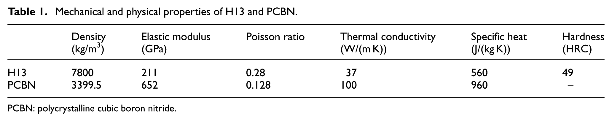
PCBN: polycrystalline cubic boron nitride.
Cutting parameters for orthogonal cutting tests.


Experimental setup to analyze and save cutting forces data. 23
Finite element model
The commercial FE package ABAQUS/Explicit®24 has been used to model serrated chip formation in high strength alloy steel. In ABAQUS/Explicit no iteration is performed and the solution is determined by advancing the kinematic state from the last increment. 25
A 2D FE model with plane strain assumption is employed to simulate the orthogonal cutting experiments. Chip morphology transition in high strength alloy steel is modeled using Lagrangian approach, that is, the workpiece is fixed and the tool moves with the selected cutting speed. The feed rate is adjusted by the vertical penetration depth of the cutting tool with respect to the workpiece. Chip separation from the workpiece and crack formation in the chip is realized using element deletion technique based on Johnson–Cook shear failure criteria. 26 Elements are deleted from the model when equivalent plastic strain value reaches a critical limit.
A total of around 4000 CPE4RT (continuum plain strain, reduced integration with temperature degree of freedom) elements were designed on the workpiece and the cutting tool for the FE model. A comparatively finer mesh was used for the chip part of the workpiece to account for high stress and temperature gradients as shown in Figure 2.

FE model for the workpiece and the cutting tool.
Smooth particles hydrodynamics model
SPH model was built using LS-Dyna explicit® code. Since the tool was considered as rigid, only the workpiece was modeled with SPH particles. A uniform spacing of 0.02 mm was used between the particles as shown in Figure 3. As discussed later, renormalized formulation was used in all SPH models. In addition, all smoothing length parameters were set to default values. 27 In contrast to the FE model, a honed edge tool was utilized in the SPH model.

SPH model for the workpiece and the cutting tool.
The default SPH formulation is unable to manipulate correct particles distributions around the contact boundaries due to lack of neighbor particles. To overcome this problem, an alternative formulation called renormalized formulation is proposed by LS-Dyna. This method is based on the work of Randles and Libersky 28 and Vila. 29 With this method, a better distribution of particles around the contact boundaries is obtained which results in precise calculated quantities.
All SPH models were run with renormalized formulation. The default SPH formulation gives very high tool–chip contact length and is unable to accommodate any frictional effects. Hence, this method results in an unrealistic chip flow. The difference in chip formation using default and renormalized formulation is shown in Figure 4.
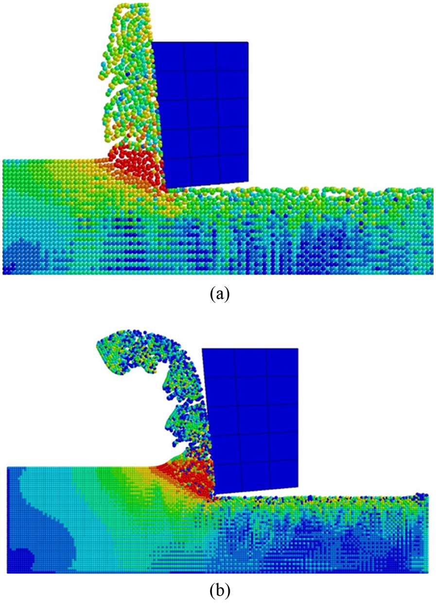
Difference in chip formation between (a) default and (b) renormalized SPH formulations.
Although the distribution of particles around the rake face has been improved in the renormalized formulation, the flow of particles around the tool tip adjacent to the flank face shows strange behavior. The particles stay away from the tool tip and flank face resulting in a gap of few microns. This problem can be solved using a honed tool edge which results in a more realistic material flow around the tool tip. The difference with using a sharp and honed tool edge is shown in Figure 5. However, this approach results in an increase in computational time by around 30% due to increase in contact area.

Material flow in SPH models around (a) sharp and (b) honed edged tools.
Material modeling
The workpiece material was represented by the Johnson–Cook plasticity model. The Johnson–Cook formulation involves the yield stress σ at nonzero strain rate, strain hardening index n, equivalent plastic strain ε, equivalent plastic strain rate
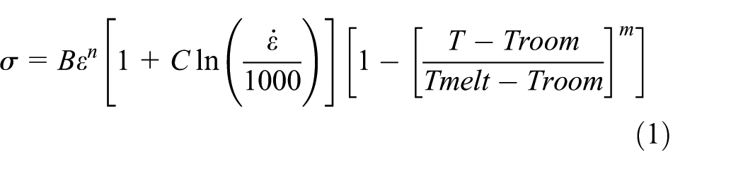
where for AISI H13, B = 981.7 MPa, C = 0.023, n = 0.182, m = 2.7, Tmelt = 1753°K, and T = operating temperature. 30
The chip separation in the chip was simulated using Johnson and Cook damage law which takes into account strain, strain rate, temperature, and pressure. 31 The damage was calculated for each element and is defined by
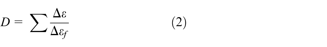
where D is the increment of equivalent plastic strain during an integration step, and

where
Johnson–Cook damage law’s parameters.

JC: Johnson–Cook.
Friction modeling
Zorev’s sliding-sticking friction model was utilized in the simulation. According to Zorev, the division of sliding and sticking region is given by 15
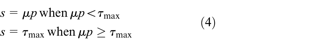
where s, p, and τ are the friction, normal, and equivalent shear stresses at the tool rake face. A constant coefficient of friction (µ) value of 0.3 was used in all simulations. The value was estimated based on the iterative method described by Özel and Altan 32 The initial value was taken as the ratio of frictional force to the normal force. The model was implemented using a static shear stress limit for the workpiece and no subroutine was utilized.
Heat generation
There are two main sources of heat generation in the model. One due to plastic deformation of the workpiece and the other is frictional work at tool–workpiece and tool–chip interfaces. The inelastic heat fraction for the workpiece was taken as 0.9 whereas fraction of frictional work converted into heat was taken as 1.0.
Results and discussion
The cutting forces at different cutting parameters from orthogonal cutting tests, finite element model (FEM), and SPH models are compared in Figure 6. It can be seen that for both feed rate values cutting and thrust forces are not much affected by varying cutting speed. With feed rate of 0.25 mm/rev, cutting forces obtained are between 1200 and 1250 N, whereas the thrust forces are found to be between 800 and 900 N. Decreasing the feed rate to 0.15 mm/rev results in reduction in cutting forces by 40% as shown in Figure 6. The same results in a reduction in thrust forces by around 60%. The predicted values of cutting and thrust forces from FEM and SPH models show similar trends. FEM models slightly overestimate the cutting and thrust forces with an average error of 5%. In contrast, SPH models show lower cutting forces. This may be due to different chip separation criteria used in the two models. Also the contact formulation between SPH and FE parts in LS-Dyna is significantly different from the default kinematic formulation in Abaqus Explicit. This also results in reduced cutting forces. SPH models with sharp cutting tool are unable to predict thrust forces due to restricted material flow and need a honed edged tool for thrust force predictions. The average error for SPH models is around 8%.

Cutting and thrust forces obtained at feed of (a) 0.25 and (b) 0.15 mm/rev, respectively.
The chip morphologies obtained from FE and SPH models at a feed of 0.25 mm/rev with different cutting speeds are shown in Figures 7 and 8, respectively. Serrated chips are predicted by both models and the frequency of serration increases with cutting speed. The SEM chip examinations also reveal similar pattern as shown in Figure 9. Both FE and SPH models show that length of cracks increases with cutting speed. This is also confirmed by SEM photographs as shown in Figure 8.
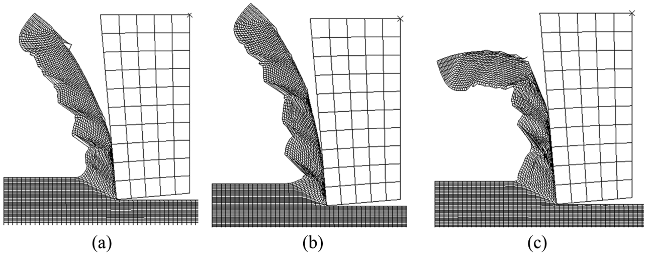
Chip morphologies from FE model at cutting speeds of (a) 150, (b) 200, and (c) 250 m/min.

Chip morphologies from SPH model at cutting speeds of (a) 150, (b) 200, and (c) 250 m/min.

SEM photographs of serrated chips at cutting speeds of (a) 150, (b) 200, and (c) 250 m/min.
These figures also show that intensity of cracks increases with cutting speed which is also revealed by SEM photograph. The chip curl increases with cutting speed due to increase in crack lengths. Length of cracks decreases when the feed rate is reduced to 0.15 mm/rev as shown in Figures 12 and 13. This is also reported by Ng and Aspinwall. 15 Chip morphologies for the SPH models also show similar trends; however, the chip curl is more due to weak cohesive forces between the chip segments. Serrated chip morphology can be described quantitatively via three parameters, namely, peak, valley, and spacing as shown in Figure 10. A comparative analysis of the parameters’ average values in Figure 11 shows reasonable agreement with experimental results for both models.

Serrated chip morphology parameters.

Serrated chip morphology parameters by experiments and models at feed of 0.25 mm/rev.

Mises stress contours for FE model at feed rate of (a) 0.25 and (b) 0.15 mm/rev (cutting speed = 250 m/min).
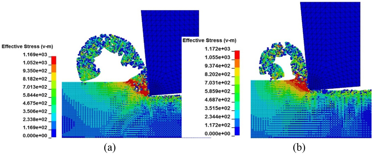
Mises stress contours for SPH model at feed rate of (a) 0.25 and (b) 0.15 mm/rev (cutting speed = 250 m/min).
Figures 12 and 13 also show Mises stress contours for FE and SPH models, respectively. Both models show similar stress pattern with highest Mises stress at the primary shear zone and cyclic variation of stresses along the chip segments. As with the cutting forces, stresses are not much affected by cutting speed and are approximately constant. Reduction in feed rate leads to increases in stresses for both models as shown in Figures 11 and 12. This mainly accounts for size factor due to increase in specific cutting energy at lower feed values. 33 In comparison to FE models, SPH models show low stresses and high chip curl. The low values are because of the absence of mesh. It has been investigated that very fine particles spacing results in stress, strain values close to FE models. However, it would be very much computationally expensive. The developed SPH models are on the average 14 times more computationally expensive than FE models.
Temperature contour at the workpiece and cutting tool is shown Figure 14(a). Temperatures are highest at the tool–chip interface and are between 700°C and 720°C. Unlike continuous chips, temperatures are not uniform and are higher in the chip segments due to slow heat transfer at higher cutting speeds. Figure 14(b) shows that temperatures are increasing with cutting speed and decreasing with the feed rate. No experiments were performed to verify the results; however, the range of temperatures and behavior predicted by FE models are in agreement with similar studies on high speed turning of H13.15,34,35 Only FE models are able to predict temperatures as the SPH solver utilized in this study is unable to perform coupled temperature displacement analysis.
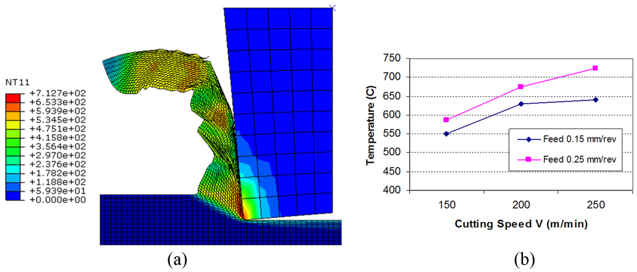
(a) Temperature contour at cutting speed of 250 m/min and feed rate of 0.25 mm/rev. (b) Variation in tool–chip interface temperature with cutting speeds and feed rates.
Figure 15 shows equivalent plastic strain (PEEQ) contour at feed rate of 0.25 mm/rev and cutting speed of 250 m/min obtained with FE and SPH models. Both models show a repeating pattern for PEEQ values and are comparatively higher at the shear bands between the chip segments. In contrast, Figure 16 shows a uniform and low PEEQ contour at cutting speed of 50 m/min for both FE and SPH models. Similar findings were reported by Arrazola et al. 16 while modeling machining of AISI 4140 using the ALE approach. SPH models also show similar pattern with low values of PEEQ as compared to FE models.
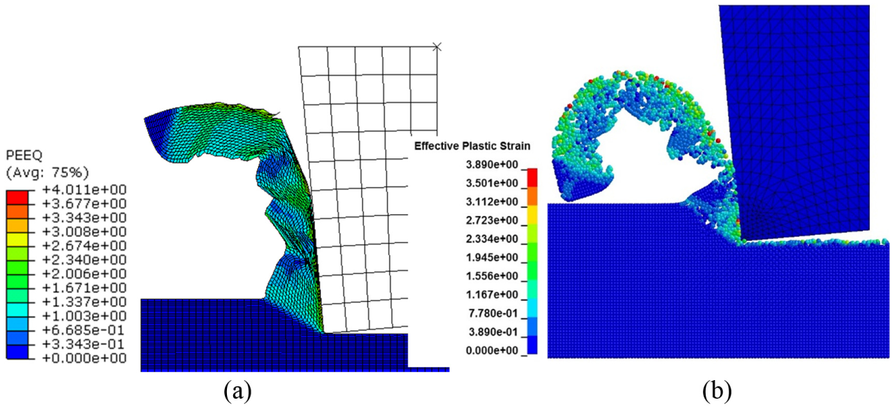
Equivalent plastic strain contour for (a) FE and (b) SPH models at cutting speed of 250 m/min (feed rate = 0.25 mm/rev).

Equivalent plastic strain contour for (a) FE and (b) SPH models at cutting speed of 50 m/min (feed rate = 0.25 mm/rev).
The FE and SPH models developed for serrated chip formation are able to predict chip morphology changes from continuous to serrated and from serrated to discontinuous chips as shown in Figures 16 and 17. Figure 16 shows continuous chip formation at low cutting speed while Figure 17 shows discontinuous chips formed at high cutting speed, that is, at 400 m/min.

Discontinuous chip at cutting speed of 400 m/min with (a) FE and (b) SPH models.
Conclusion
The FE and SPH models developed in this research can simulate chip morphology and other process variables with reasonable degree of accuracy.
Serrated chips are observed in the cutting speed range of 150–250 m/min and they are successfully simulated by FE and SPH models.
Cutting forces in the high-speed range are unaffected by change in cutting speed. On the other hand, feed rate has marked effect on cutting forces which is also predicted by FE and SPH models with an average error of around 5% and 8%, respectively.
The SPH and FE models can predict chip morphology changes from continuous to segmented and from segmented to discontinuous chip by varying the cutting speed.
SPH models are able to simulate the correct stress and strain distributions with no need for a geometric or mesh-based chip separation criteria.
Tool edge preparation can easily be modeled with SPH as compared to FE models.
SPH models show low cutting forces and higher chip curl as compared to FE models when using similar sets of material and friction parameters.
Footnotes
Academic Editor: David R Salgado
Declaration of conflicting interests
The author(s) declared no potential conflicts of interest with respect to the research, authorship, and/or publication of this article.
Funding
The author(s) disclosed receipt of the following financial support for the research, authorship, and/or publication of this article: The project is financially supported by King Saud University, Vice Deanship of Research Chairs.