
Abstract
Due to high efficiency in helping breaking rocks, positive displacement motor has a widespread application in the field of oil and gas drilling engineering. However, service life of positive displacement motor becomes shorter resulting from failure of the driving shaft thread. The three-dimensional simulation model of driving shaft’s connecting thread has been developed based on the principle of virtual work, Von Mises yield criterion, and contact nonlinear theory. This article has put forward the plan to optimize structure of driving shaft with straight thread based on the design principle of double-shouldered thread; besides, fatigue life of driving shaft with straight thread before and after optimization has been assessed by resorting to the multiaxial fatigue principle and Brown–Miller critical plane rule. In line with research results, mechanical properties of driving shaft with straight thread are superior to those of driving shaft with taper thread. Under the load of axial drill pressure with fluctuation and alternating torque, fatigue life of driving shaft with straight thread after optimization is greatly improved. This article has not only provided basis for optimizing connecting thread of driving shaft but also boasts of high engineering value for improving service life of positive displacement motor.
Keywords
Introduction
With constant improvement on drilling technology, and popularization of direction well technology, horizontal well technology, and sidetracking well technology (STH), market demand of positive displacement motor (PDM) is on increase. Taking Chinese market as an example, output and sales of PDM grow very fast. PDM with longer service life is necessary for efficient drilling. Especially in deep well and offshore drilling, when the life of PDM doubles, the cost saved will be more than five times the price of drill. Take the Chinese 5000-m-deep well as an example: in case of failure of PDM, it takes 1 day to restore the operation, and drilling cost is significantly increased. Therefore, PDM vendors take extension of PDM service life as the research focus.
When working in the bottom hole, PDM usually needs to bear a few tons or even tens of tons of axial load, aside from strong impact load. Driving shaft is the key part of connecting the drill bit with the power parts of PDM. Among the driving shaft assembly, upper thread of driving shaft is very easily damaged because it directly transmits torque and withstands hydraulic thrust of motor. Therefore, it severely restricts service life of PDM. Affected by short life of driving shaft (mainly arising out of failure of root of upper thread thereof) to a large extent, service life of PDM is only approximately 120–150 h. 1 At present, notwithstanding multiple types of threads, systemic analysis on end thread has not been found out. Thus, it is of utmost engineering value to conduct research on mechanical properties of connecting thread of driving shaft.
In recent years, many researchers have studied the structure and mechanical behavior of the connecting thread of petroleum drilling tools. AR Shahani and SMH Sharifi 2 of K. N. Toosi University of Technology completed the contact stress analysis of tool joint and utilized formulas to forecast the fatigue life of tool joint. According to the research result, maximum value of stress concentration factor is located in the root of first thread tooth of pin joint; NH Dao and H Sellami 3 of Paris Higher Mining University used the Walker Fatigue Crack Growth Rate Law to study the evolution of parameters of the surface fatigue crack growth process about drill pipe; C Santus 4 took advantage of critical distance theory and optimized Whöhler curve to explain the fretting fatigue between steel material and aluminum alloy in tool joint; Y-H Lin et al. 5 applied contact mechanics theory to establish the quasi three-dimensional finite element semi-analytical theory, deriving the displacement and stiffness matrix of drilling thread under any load; S-L Chen et al. 6 analyzed the connecting thread of the drill pipe using the elastic finite element method and then found out it could reduce thread stress by adding the stress relief groove and changing the taper of the joint; X-H Zhu et al. 7 provided an effective guidance for reducing the thread gluing accidents by establishing a new three-dimensional thread structure. However, analyses of the thread of drilling rig are mainly focused on drill pipe and collar, while research on the mechanical properties and fatigue life of the thread of PDM is relatively rare.
Based on studying the static mechanical properties of the upper thread of driving shaft, this article analyzed and compared the fatigue life of different types of thread under variable load. After optimizing existing structure, this article again conducts research on fatigue life’s sensitivity toward load component. Therefore, such research is of utmost engineering value to improve service life of PDM.
Analysis of failure and material properties of thread of driving shaft
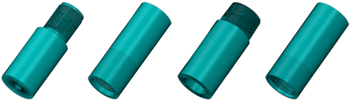
Pursuant to domestic types of upper connecting thread of driving shaft commonly used by vendors, Φ172 mm PDM is taken as an example. Figure 1 shows two common kinds of non-API 8 threads. Non-API thread is composed of straight thread and taper thread. Straight thread mainly differs in terms of number of thread teeth, while taper thread mainly differs with respect to number of thread teeth and taper, generally speaking, taper of such taper thread is 1:6.
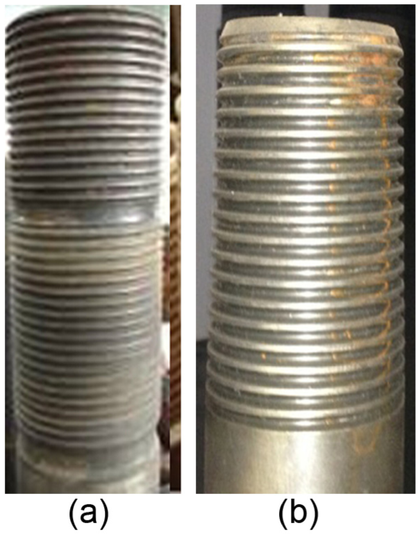
(a) Upper direct thread and (b) taper thread of Φ172 mm driving shaft.
The down hole drilling condition in field driving is extremely harsh. High temperature, high frequency impact, and stick–slip oscillation pose serious damage to down hole tools. Driving shaft thread serves as a crucial part of down hole drilling rig to transmit axial load and driving torque. It has been an important factor to affect service life of PDM whether the thread of driving shaft is subject to fatigue destruction under high impact and alternating torque. Figure 2 represents several thread failures commonly encountered: broken end thread tooth, thread root rupture, and so on.

Failed thread arising out of erosion and fatigue failure of thread teeth.
So as to locate reasons for thread failure, mechanical properties of material of driving shaft shall be studied. Driving shaft of PDM is made of 42CrMo alloy. When machining driving shaft thread, the material rotates and there is an axial feed of material at the same time while the cutting tool stays put. Heat treatment of 42CrMo alloy is composed of annealing, and hardening and tempering. With respect to annealing, sustain temperature at 850°C for 3 h and cool the furnace till 400°C while discharge side adopts air cooling. During hardening and tempering, maintain temperature at 850°C for 1 h and make tempering in 560°C after oil quenching. Y-T Li et al. 9 have done an experiment on mechanical properties of 42CrMo alloy, with results given in Table 1.
Test results of mechanical performance of 42CrMo.

Test results of mechanical properties show that the intensity of the three 42CrMo samples does not differ much, and it means that homogeneity of 42CrMo alloy is good; the tensile and yield strength of the material are both in the range of API. Therefore, failure of upper thread of driving shaft is not caused by material. Instead, it may more likely arise out of easy failure of a certain type of thread. In response to such hypothesis, simulation analysis on load-bearing performance of single-shouldered straight thread and taper thread is conducted.
Loading analysis of the thread of driving shaft
Upper thread of the driving shaft is connected to the diverter cap. Due to bending moment on underpart of driving shaft and underpart TC bearing, upper thread of driving shaft during operation is acted by axial variable load Fy and torsion load M. However, Cardan shaft converts planetary plane motion into fixed axis rotation of driving shaft. Thus, upper thread of driving shaft bears radial load Fr changing with the direction of rotation of Cardan shaft. With the vibration of drilling, such load also varies. Fr load (instantaneous) is given in Figure 3. In Figure 3, rotor, Cardan shaft, and driving shaft are shown from top to bottom, respectively. Fr is produced mainly because of the centrifugal inertia force of the rotor and the Cardan shaft.

Load bearing of parts of PDM.
The centrifugal inertia force generated by the multithreaded rotor (suppose N headed) in motion is Fg 10

where m is the mass of rotor, N is the number of threads of the rotor,
In the process of directional drilling, the centrifugal inertia force generated by the Cardan shaft is Fzg

where Mz is the mass of Cardan shaft, Rz is the centroid of the rotation radius of Cardan shaft, and
The upper part of rotor is the safety anti-drop device of PDM. It is herein considered as hinged bearing, which is marked as O1, and considering Cardan shaft and rotor as research objects, the distance between O2 and O1 marked toward direction Z is Lg. The distance between O2 and O toward Z is Lzg and the distance between Fr’s active line and O1 is Lr. Take O as the starting point of direction Z and make a sum of the moments of O1, which is given as follows
Force exerted by Cardan shaft on the driving shaft is same as Fr in magnitude, but opposite in direction. Even under the non-deflection section, the driving shaft also withstands bending momentum changing with the rotating drilling bit.
This article focuses on researching the loading and fatigue status of thread of driving shaft. In order to simplify research and neglect minor factors, upper parts of TC bearing and diverter cap are simplified during model establishment. The loading models are shown in Figures 4 and 5; the Y-axis is the direction of well drilling, in which Fr is the force generated by the centrifugal inertia force of rotor and Cardan shaft, M is the actual output torque, and Fy includes hydraulic thrust G1 produced by rotor and self-weight Gg of rotor and Cardan shaft


Load bearing of driving shaft with taper thread (instantaneous).
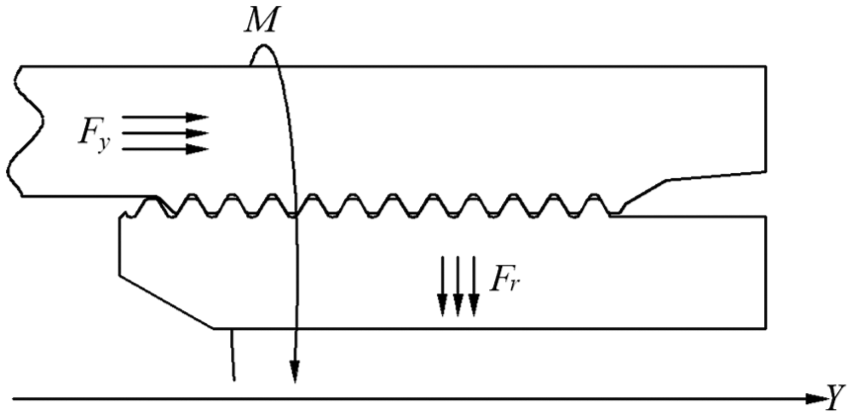
Load bearing of driving shaft with straight thread (instantaneous).
The bottom of PDM is connected to drill bit; therefore, the load borne to upper thread of the driving shaft is almost same as the drill bit. In the meantime, they simultaneously withstand variable axial load and torque, which are shown in Figures 6 and 7. 11

Variable axial load borne to thread of driving shaft.
Variable load of torque borne to thread of driving shaft.
Analysis on mechanical properties and fatigue life of thread
Dynamic finite element model
The contact surface of the pin thread and the box thread is a complex spatial spiral surface. Its force bearing analysis involves material nonlinearity, geometric nonlinearity, and contact nonlinearity. Therefore, it is quite difficult to establish a complete and accurate mathematical model and obtain the analytical solution. At present, the problem is solved by finite element method.
For the 3D calculation of the thread joint, the implicit algorithm makes calculation difficult due to the inconsistency of contact in between shoulder and mesh surface of thread teeth under states such as separation, adhesive contact, and slide contact. Besides, the existence of material and geometric nonlinearity further increases difficulties of seeking solution. 12 However, the explicit method during calculation presents explicit progression (iteration is not required). Thus, it is very suitable for calculating high nonlinearity akin to 3D thread mesh. Therefore, ABAQUS/Explicit algorithm is adopted herein for simulation calculation.
Explicit algorithm uses the central difference method to accomplish the time integration of the equations of motion, and the dynamic conditions of the next incremental step are obtained using the dynamic conditions of the previous incremental step. 13 At the t moment, the dynamic equilibrium equations of the nodes are as follows

where M is the mass matrix of node, u is the displacement of node, P is an external force applied, and I is the internal stress of element.
Making the time integration to formula (5) can calculate the speed and displacement of the node


According to the constitutive relation of the material, the element stress can be calculated

where
Parameters of finite element model of thread of driving shaft
A three-dimensional model is established according to the type of connecting thread of the driving shaft of Φ172 mm PDM. In order to establish the three-dimensional thread model with high accuracy and computational efficiency, the dividing method of dividing block is applied to complete the meshes of thread joint, the fine mesh is applied in the thread segment, and the sparse mesh is applied in the part far from the threaded segment. Figure 8 shows the finite element models. The element type is C3D8R. The specific parameters of the finite element model are given in Table 2.
Finite element models of thread.
Simulation parameters.

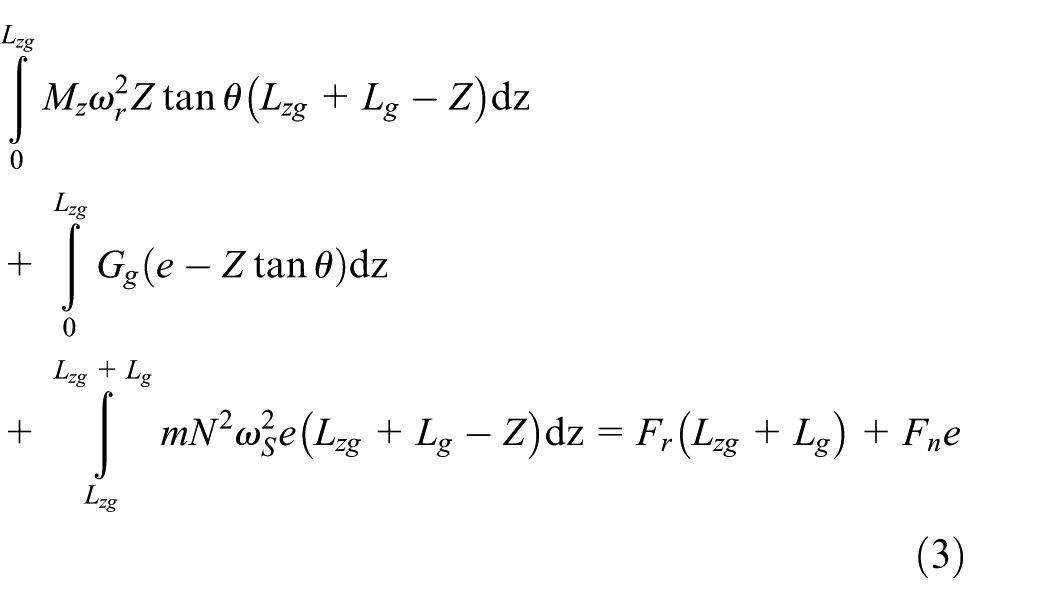
Connection control equation of thread
The finite element connection control equation of thread is 15

where
Comparative analysis of the stress between straight thread and taper thread
In this part, stress analysis of straight thread and taper thread of the driving shaft is accomplished, and the working load of driving shaft is loaded to the finite element models: torque of 10 kN m and axial load of 150 kN. For the driving shaft with straight thread, this article only discusses the part connected to diverter cap. Figures 9 and 10 show the comparison of contact pressure and Mises stress between straight thread and taper thread.

Load-bearing analysis of box thread.
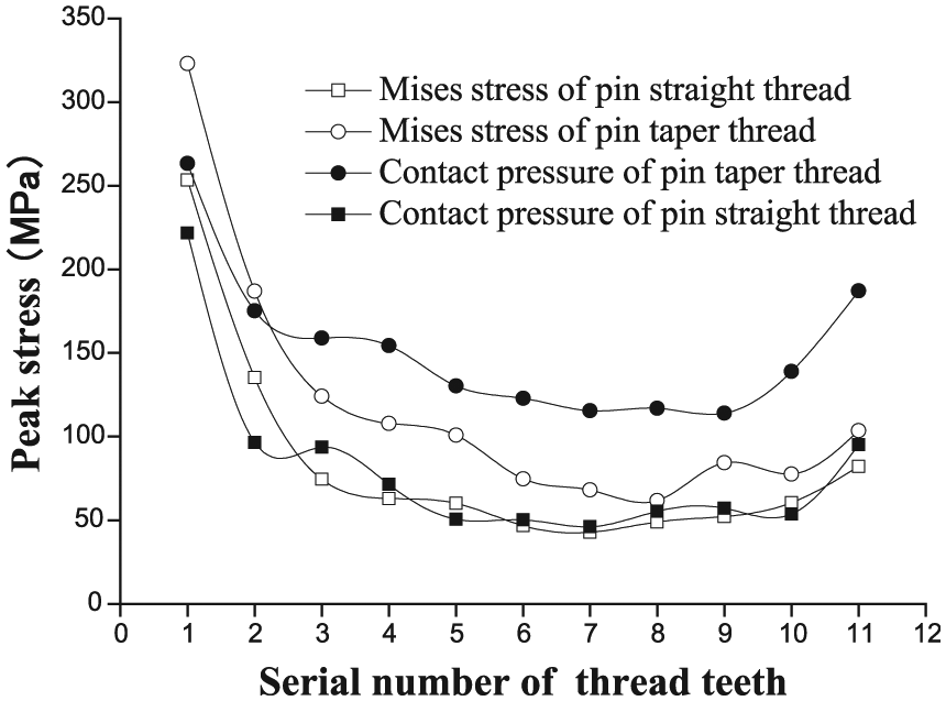
Load-bearing analysis of pin thread.
Big Mises stress and contact pressure are produced when the thread withstands axial pressure and torque load, which is given in Table 3.
Contrast of load bearing simulation result of upper direct thread and taper thread of driving shaft.

Table 3 shows that the Mises stress and contact pressure of driving shaft with straight thread are both lower than those of driving shaft with taper thread. Therefore, under the action of working conditions with large torque and large load, straight thread is preferred for the driving shaft. Meanwhile, the contact pressure of taper thread is obviously higher than that of the straight thread; contact pressure, to a certain extent, reflects the sealing performance of the thread, and therefore, in the condition of high sealing requirements, the taper thread is a better choice for the driving shaft. However, in most cases, the sealing performance requirement of the thread of driving shaft is not very high, and too large contact pressure will lead to thread gluing accidents. Therefore, from the aspects of normal working conditions and reduced probability of thread gluing accidents, straight thread is preferred for the driving shaft.
Analysis of fatigue life
According to the load conditions of the driving shaft, the static mechanical properties of the driving shaft are analyzed, but the load conditions of driving shaft are extremely complicated during the drilling process. Therefore, it is necessary to carry out not only the static analysis of the structure but also the analysis and calculation of fatigue life of dynamic load–time process. Purely in terms of bearing stress state, analysis on fatigue can be roughly divided into uniaxial and multiaxial fatigue. The fatigue damage of the upper thread of driving shaft is a kind of typical non-proportional multiaxial fatigue damage. However, cost arising out of fatigue test is quite expensive, and adoption of proper fatigue simulation model under the precondition of saving cost may also produce results with higher accuracy; therefore, FE-SAFE fatigue analysis software is adopted herein for fatigue life analysis.
Verification of fatigue life calculation model
To verify the accuracy of the fatigue life calculation model, three-dimensional finite element model of thread for the same structure is established based on NOV Grant’s fatigue test data 16 of REG-6/8 joint. Again, fatigue calculation method herein is used to calculate fatigue life of REG-6/8 structure under the same load condition, with contrasting results given in Figure 11.

Comparison of simulation results and experimental results.
The data that NOV Grant company gets from fatigue experiment toward REG6-6/8 joint have four groups, which are regarded as the abscissas of the spots of fatigue life dispersion zone in Figure 11; the simulation results of fatigue life are taken as ordinate of the spots of fatigue life dispersion zone in Figure 11. Based on contrast and analysis results of simulation and experiment results, all spots are found to be located in double-dispersion zone, indicating a high consistency between simulation results and experiment results. And again, all the material parameters used in simulation model are lower limit as provided by the prevailing standard, while those of materials used in actual production are usually higher than specified value. As a result, the simulation results and experiment results have highest similarity, with smallest error of service life only at 2%, and the calculation results are inclined in the safe side. So, the fatigue life calculation model established herein can be used to conduct calculation related to fatigue life of thread joints.
Load–time process
Driving shaft during drilling mainly withstands three types of alternating loads: radial load Fr, axial weight on bit, and torque, but the three loads changed according to the time and the revolution of rotor. Moreover, the peak values of the three loads have phase difference with the passage of time, and it belongs to non-proportional loading. The variation rule of load is subject to the random vibration theory. When the drilling bit breaks rocks, vibration characteristics vary around an average value.
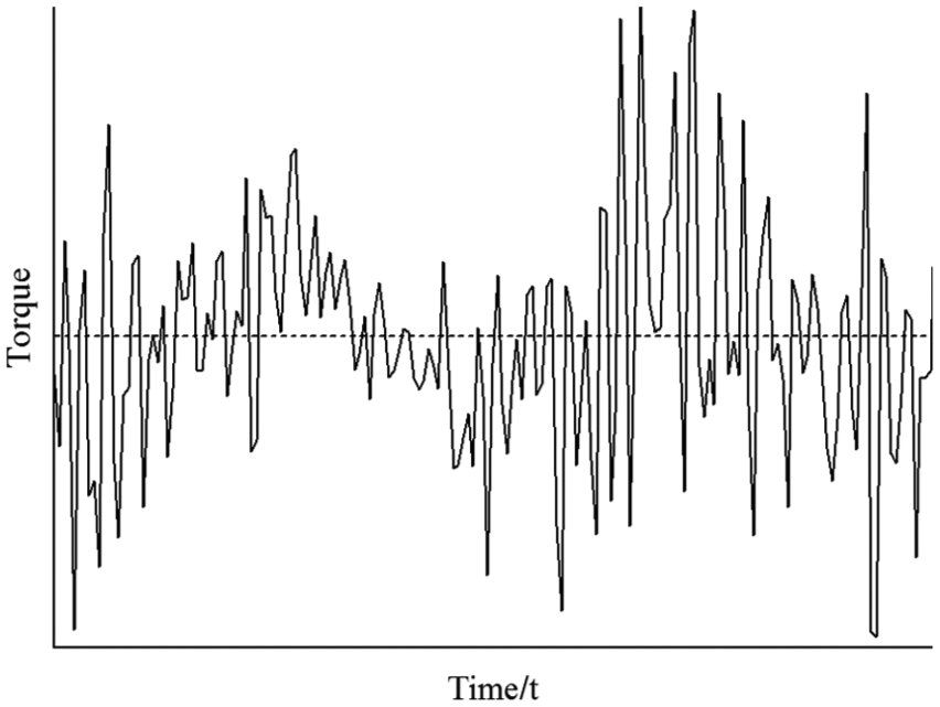
Figures 12 and 13 represent torque–time process and axial load–time process, respectively, in a depth of 4 km calculated by full well dynamics equation with the time span of 3 s. During this time span, very violent radial load, axial load, and torque experienced by the driving shaft pose very big influence on the fatigue life of structure.

Torque–time process.
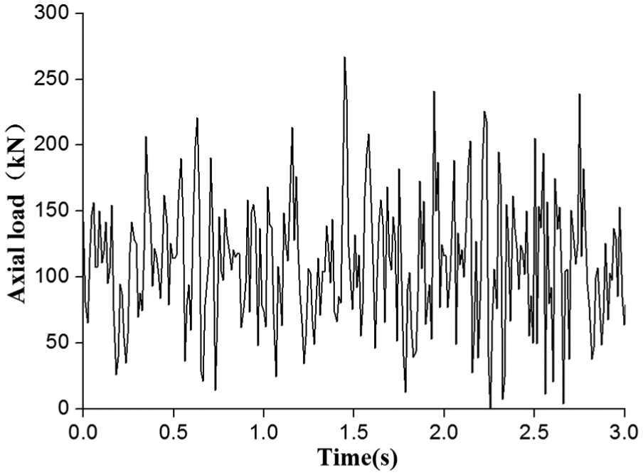
Axial load–time process.
The size and direction of radial load Fr change with the revolution of rotor; in Figure 3, point O, x-axis, and y-axis form the plane OXY. Set the angle between Fr and x-axis as β. The Fr is decomposed into Fx and Fy in the two directions of XY, so the relationship between them is


The rotation speed of rotor is 150 r/min, recognizing the size of Fr as “1,” so in the period of 3 s, the load–time processes of Fx and Fy are shown in Figures 14 and 15, respectively.

Load–time process of Fx.
Load–time process of Fy.
Take the analysis example of this article as an example and set 4 km as drilling depth and the bore diameter as 213 mm. According to Hamilton principle and finite element method, the equation of dynamic model of a 3D full well drilling string system is calculated as follows 17

where M is the mass matrix of the drill string system, C is the damping matrix of the drill string system, K is the stiffness matrix of the drill string system,
Material parameters and fatigue calculation model
The driving shaft is made of 42CrMo alloy, which meets with requirements of poor working conditions of PDM. FE-SAFE’s material library contains Seeger 18 approximation algorithm. Material’s tensile limit (ultimate tensile strength (UTS)) and the elastic modulus can be used to generate approximate material fatigue data. Figure 16 shows S-N curve of 42CrMo.

Brown and Miller
23
proposed a critical plane theory to regard the range of maximum shear strain

where
Fatigue analysis results
Under the action of alternating load, all the fatigue failure of straight thread and taper thread happened. Fatigue damages are both in the first effectively engaging thread tooth of pin thread. This is consistent with the engineering practice. The fatigue analysis results are compared in Table 4.
Fatigue life simulation results of straight thread and taper thread of driving shaft.

The time span of alternating load is 3 s, so the minimum fatigue life of straight thread and taper thread are 225 and 162 h, respectively. The results show that the driving shaft with straight thread has higher fatigue life, and stress level is one of the indicators which affect the fatigue life, also subject to influence by the loading form, stress concentration, and so on.
Structural optimization and quantitative analysis of load components
Structural optimization
From the foregoing analysis, it is known that the fatigue life of driving shaft with straight thread is higher than that of driving shaft with taper thread. But the existing straight thread structure still has the improvement space. Based on the existing structure and API standard, this article proposes an improved method for the connecting thread of the driving shaft (Figure 17).

Structure chart of the upper thread of driving shaft: (a) original structure and (b) optimized structure.
In the original structure, the top of the driving shaft is connected to the diverter cap. On account of that, there is a tool withdrawal groove at the end of the box thread of diverter cap, so the end face of driving shaft has a certain distance from the internal end face of the diverter cap. According to the design principle of double-shouldered thread, the convex table, having the same width with tool withdrawal groove, is machined before preparing upper connecting thread of driving shaft, and the convex table contacts with inside end surface of diverter cap to form supporting shoulder so that anti-torsion performance of upper connecting thread of driving shaft is thus improved. In the meantime, so as to enhance anti-bending performance of thread, key structure parameters of thread are optimized based on orthogonal optimization method. Conclusions are thus drawn: thread form angle: 90° and pitch: 3 teeth/in; based on such conclusion, anti-bending strength of thread is thus greatly improved.
Influence of axial load component on the fatigue life of the thread of driving shaft
The PDM is located in the upper part of the drill bit; therefore, the axial load of the PDM is pressure. In case of pure study on axial load, even under very rare extremely high work condition (instantaneous drill pressure more than 500 kN), axial load exerts very little influence on fatigue. Therefore, pure study on axial load’s influence on the fatigue life of driving shaft is of no big significance. Therefore, research shall have its focus on the influence on fatigue life of driving shaft by bending moment and torque.
Influence of torque load component on the fatigue life of the thread of driving shaft
During the drilling process, the PDM functions to transmit torque. On account of the influence of the make-up torque and the down hole working conditions, the torque of the172 mm PDM is not more than 20 kN m, and the torque has large effect on the fatigue life of thread; therefore, the fatigue life of the single-/double-shouldered driving shaft thread is studied when the torque load is 10, 12, 14, 16, 18, and 20 kN m.
The definition of the life prediction dispersion zone is

where NS is the predicted fatigue life of single-shouldered driving shaft thread and ND is the predicted fatigue life of double-shouldered driving shaft thread.
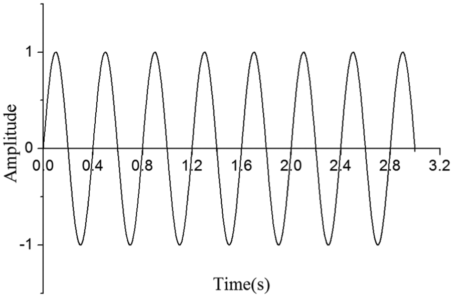
In comparing the sensitivity of the fatigue life of the single-/double-shouldered driving shaft thread for each load component, all the load spectra are expressed by sinusoidal load. Figure 18 shows the sinusoidal load. Figure 19 shows the calculation results of fatigue life.
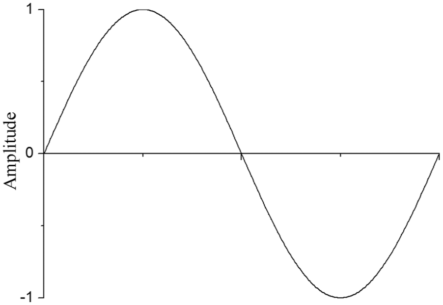
Sinusoidal loads.

Fatigue life dispersion zone of torque.
Figure 19 shows that torque ranges from 10 to 20 kN m, the fatigue life of double-shouldered thread is much higher than that of single-shouldered thread, and all the spots are not located in double-dispersion zone. In the structure design, the fatigue limit of the structure is usually based on the load cycle times of 107; on this basis, the torque fatigue limit of single-shouldered thread is located in the range of 10–12 kN m. If the torque load exceeds this range, the load cycle times will not reach 107. However, the torque fatigue limit of double-shouldered thread is located in the range of 14–16kN m, which has an increase of 14.3%–37.5% compared to the single-shouldered thread. It is thus concluded that the anti-torque performance and fatigue life acted by torque of double-shouldered thread are far superior to those of single-shouldered thread.
Influence of bending moment load component on the fatigue life of the thread of driving shaft
At the angle build stage of drilling process, with the constant change of build-up rate and the continuous rotation of the drill bit, the driving shaft must be subjected to the bending moment M, and the size and direction of M are constantly changing. To conduct a quantitative calculation, the M is converted to a radial load FM, and in addition, through formulas (10) and (11), FM is decomposed into FMx and FMy, which are perpendicular to each other.
The fatigue life of the single-/double-shouldered driving shaft thread is studied when the FM are 80, 90, 110, 120, 140, and 150 kN. And the load spectra are still expressed by sinusoidal load. Figure 20 shows the calculation results of fatigue life.

Fatigue life dispersion zone of bending moment.
Analogously, the radial load ranges from 80 to 150 kN, and the fatigue life of double-shouldered thread is still much higher than that of single-shouldered thread, and all the spots are not located in double-dispersion zone. The radial load fatigue limit (bending moment fatigue limit) of single-shouldered thread is located in the range of 80–90 kN. If the radial load exceeds this range, the load cycle times will not reach 107. However, the fatigue limit of radial load (bending momentum) of double-shouldered thread is 120–140 kN, which has an increase of 25%–42.8% compared with that of single-shouldered thread. It is thus concluded that the anti-torque performance and bending fatigue limit of double-shouldered thread after modification have a great improvement compared to those of single-shouldered thread.
Conclusion
The 3D numerical simulation model is used herein to conduct the simulation of thread of the driving shaft, and the fatigue life prediction model is established based on the BM critical plane rule. By comparing the calculation results of the two models, the performance of the existing two kinds of thread structure is evaluated. The calculation results are relatively in agreement with the actual data, and such an importance conclusion as straight thread is more favorable for extending service life is thus drawn. Under the same working conditions, the fatigue life of the driving shaft with straight thread is 28% higher than that of the driving shaft with taper thread.
Based on the existing straight thread plan, improvement measures are proposed herein. After calculation based on the mathematic model established herein, it is known that the improvement plan may help increase anti-torque fatigue life by 14.3%–37.5% and bending moment fatigue limit by 25%–42.8%; generally speaking, improvement plan will significantly improve service life of thread as long as approximately 300 h, just commensurate with “return drill.” Therefore, such move will help greatly save drilling cost.
Footnotes
Academic Editor: Yongming Liu
Declaration of conflicting interests
The author(s) declared no potential conflicts of interest with respect to the research, authorship, and/or publication of this article.
Funding
The author(s) disclosed receipt of the following financial support for the research, authorship, and/or publication of this article: This work reported in this article was supported by the Natural Science Fund for Outstanding Youth Science Fund (Grant No. 51222406), New Century Excellent Talents in University of China (NCET-12-1061), Youth Scientific Research Innovation Team Project of Sichuan Province (2014TD0025), International Cooperation Project of Sichuan Science and Technology plan (2016HH0008).