
Abstract
In new drilling conditions such as extended reach drilling or long horizontal well, to avoid large friction between drill string and wellbore or weigh on bit decreasing, a new drilling vibration tool (called antifriction oscillator) is presented in this article. For discussing its working mechanism and performance, first, the kinematics models are established based on the structure design parameter, and then the horizontal vibration models are presented according to drilling conditions. With the numerical example results, it can be concluded that the frequency of the flow area between the static and dynamic valve plates is proportional to the flow rate. Moreover, with the increasing size of static valve plate, the flow area is increasing while the total axial force is decreasing. Furthermore, according to the experiment test results with static valve plate hole diameter 35.56 mm, the vibration results are discussed by comparing with numerical example results, and it can verify the analysis models’ rationality and the calculation formulas’ correctness. The research results provide basis for theoretical research and field applications of drilling oscillator. Furthermore, by changing corresponding parameters, the research methods and models can also provide reference for the design of new methods or tools of drilling friction reduction or rate of penetration increasing technologies.
Introduction
With gradual exhaustion of oil and gas resources in shallow layers, drilling engineering is facing problems of low efficiency and high cost. For the horizontal and extended reach wells, because it can reach larger drainage area than vertical wells, and it can also solve drilling problems of some special well-types and oil layers to improve recovery efficiency, its applications in the oilfield development are becoming wider.1–3 However, during the drilling process of horizontal and extended reach well, the drill string may generate larger friction and lose weigh on bit (WOB) resulting from large borehole curvature or long horizontal section. Large friction and WOB reducing not only seriously affect the rate of penetration (ROP) of the horizontal well, but also may cause stick-slip, bulking, or some other downhole accidents. For avoiding these problems, the existing methods include adding lubricant in the working medium, installing rollers on the string or using new stabilizer. These methods are mostly restricted in suitable conditions, and speed-up effect is not obvious.4–7 Among these methods, the downhole vibration tools, such as fluid hammer, hydraulic impactor, and hydro-oscillator, have a good effect on drill string friction reducing and bit ROP increasing.8–10 For the complicated downhole conditions, the existing researches mainly obtain related parameters through experimental tests. Due to limitation of filed conditions and parameter acquisition, these research results cannot be used for new conditions, which prevent further development or optimization.
Considering these problems and the features of various drilling oscillators, a new oscillator (called antifriction oscillator) is presented in this article, which can use drilling fluid pressure energy for energy conversion and produce axial vibration with certain frequency and amplitude. For discussing its working mechanism and performance, the research in this article mainly includes the following parts. With the structure design of new drilling oscillator, the kinematics models are established. The horizontal vibration models are presented according to drilling conditions. With the numerical example results, the influences of key parameters are analyzed such as the frequency, flow rate, and total axial force. Finally, the experiment test results of static valve plate hole diameter 35.56 mm are discussed by comparing with numerical example results. The research results can provide basis for theoretical research and field applications of drilling oscillator, and the methods and models can also provide reference for the design of the new methods and tools of drilling friction reducing or ROP increasing technologies.
New oscillator design
The antifriction oscillator consists of oscillation section and shock absorber section. The oscillation section is a kind of mechanical energy and hydraulic energy conversion device, which links to the end of the shock absorber section, as shown in Figure 1. The oscillation section consists of stator, rotor, connector, dynamic valve plate, static valve plate, and so on. The working principle of antifriction oscillator is that high pressure mud enters the oscillation section through the shock absorber section, and then the mud drives the rotor and the dynamic valve plate to motion together, thus making the flow area between the dynamic valve plate and static valve plate changing periodically and producing the periodical axial force. With the effect of shock absorber section, the antifriction oscillator could produce continue and stable axial vibration and change the friction status of the drill string and borehole wall, which can fulfill the antifriction requirements of horizontal or extended reach wells.

The design of antifriction oscillator: (a) design of oscillation section and (b) design of shock absorber section.
Analysis models of antifriction oscillator
The lobe configuration of the stator and rotor inside the oscillator is 1:2, according to the structure characteristics of single screw motor, 11 the flow quantity of per revolution is as follows

where R is the rotor radius (mm), E is the rotor eccentricity (mm), and h is the rotor pitch (mm). Moreover, the rotational speed is as follows 11

where Q is the total flow rate (L/s) and

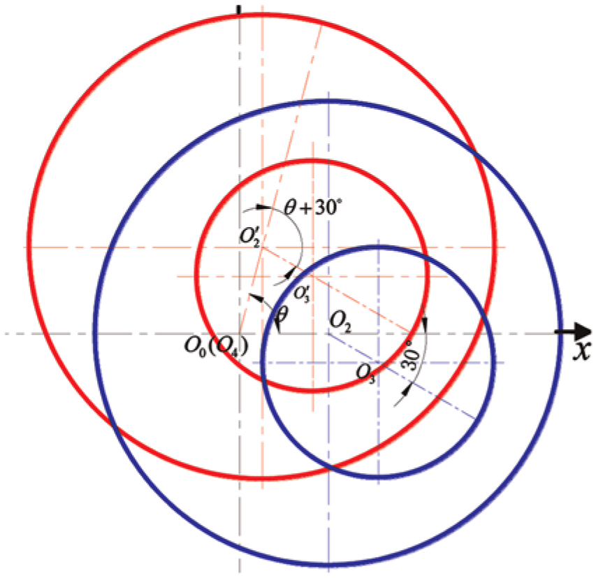
The line type of the motor stator and rotor is shown in Figure 2(a). The line type is the section contours of stator and rotor, and the stator has pure rolling relative to the rotor, which can be similarly described as the motion of point M on rotor epiphyseal line. Based on this, the motion of point M can be described as a circle, with center O1 and radius E, pure rolling in another circle with center

The kinematic relationship and line type of motor: (a) the line type of the motor stator and rotor and (b) the kinematic relationship of the motor stator and rotor.
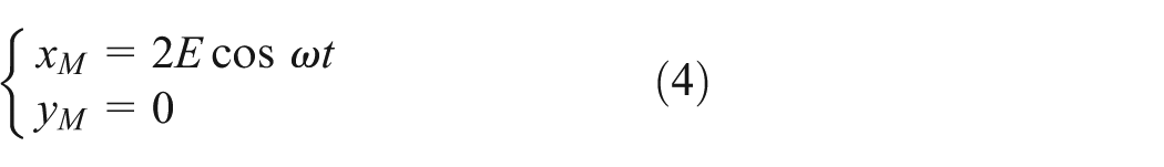
For connecting with the rotor, the dynamic valve plate and the rotor have the same movement features and results, and the eccentricity displacement of the dynamic valve plate center line relative to the tool center line is also E. At the initial time, the angle between the line

where E is the distance of
The motion of dynamic valve plate.
Figure 4 is about the changing process of the flow area between the dynamic valve plate and static valve plate in a circle, and the shade part refers to the flow area. Moreover,

The open area change of dynamic and static valve plate: (a) the initial moment, (b) the motion moment, and (c) the end of the first half period.
The center distance of circle

The length of intersecting chord AB can be obtained as follows

Setting

where

According to the downhole working characteristics of screw motor, the changing frequency of the flow area is twice as much as the rotor. The changing frequency of flow area is as follows

The expression of pressure decrease value through the motor can be described as follows 11

where

The section diagram of antifriction oscillator.
As already explained before, the expression of p1 can be given by

Herein, p is the motor input pressure value. According to the continuity equation, for the flow is constant inside the tool, so the flow rate is given by

Herein, according to the definition of flow areas, the subscript m should change from 1 to 6. The hydraulic head loss
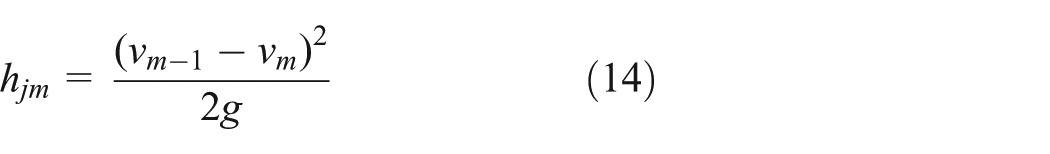
At the position of A5, the fluid channel will be narrowed and then be expanded when the drilling fluid flows from the dynamic valve eccentric hole to the static valve hole, and the hydraulic head loss of this position can be described as follows 12

Based on the equations above, the hydraulic head loss of hj5 can be obtained as follows

According to the Bernoulli equation, the pressure pm expression can be written as follows
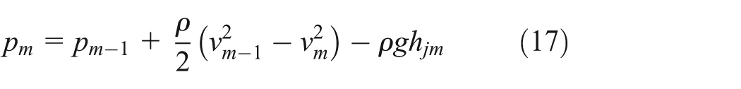
where the subscript m can be 2, 3, 4, 5, and 6; ρ is the drilling fluid density (kg/m3). Therefore, the total pressure reduction in drilling fluid through the antifriction oscillator can be computed as follows

Based on the calculation method above, the forces can be analyzed during the antifriction oscillator working process. Considering the antifriction oscillator structure and the pressures on different position, as can be seen from Figure 6, as well as the relationship between forces, pressures, and flow areas, the static pressure on the valve plate can be described as follows

where S1 is the rotor annulus area at the motor bottom position (mm), and S2 is the rotor annulus area near the connector (mm), as depicted in Figure 6.

The axial force analysis of antifriction oscillator.
Caused by the change of the flow area, the pressure pb can be formulated as follows 12

where c is the pressure propagation velocity (m/s), and the c is governed by the following equation 12

where

Moreover, the motor of rotor axial force 11 is given by

where u is the axial force coefficient, considering the antifriction oscillator downhole working conditions, we take u = 1 in the model. Hence, based on the above-mentioned expressions, the total axial force of antifriction oscillator Fz can be obtained and the result is written as follows

As mentioned before, with the definition of key parameters, the vibration model can be established. According to the downhole working conditions of antifriction oscillator, as shown in Figure 7, the vibration model can be described as follows

where

The vibration analysis model of the antifriction oscillator.
Numerical examples
In this section, based on the analysis models and calculation formulas presented before, the numerical examples were calculated and the results were discussed. Taking the structure parameters of antifriction oscillator with outer diameter 6.5″ and corresponding to the drilling field conditions, the data used in the numerical examples are given as in Table 1.
The example parameter of antifriction oscillator.

Processing numerical simulation with MATLAB software, the relationship between the change frequency of flow area and the flow rate was obtained, as shown in Figure 8. From the figure, we can get the following conclusions that the changing frequency of flow area was proportional to the flow rate. Furthermore, when the flow rate is 25 L/s, the changing frequency of flow area is 12.5 Hz.

The relationship of frequency of flow area change and flow rate.
For determining the influence of key parameters, the calculations of different diameters of static valves were carried out using MATLAB software, includes the results of flow area, reduction pressure and total axial force, as in Figures 9–11, respectively. To the flow area, as can be seen from Figure 9, the flow area is periodic changing with increase and decrease. Furthermore, as to the diameter of 1.1–1.7 in, the larger flow area corresponds to the static valve plate hole with larger diameter. However, as to the pressure reduction and the total axial force, as shown in Figures 10 and 11, compared with the results of flow area, it is periodic, changing with different trends, and the influence of static valve plate hole diameter on the total axial force is shown in Figure 11.

The flow area of different static valve plate hole diameters.

The pressure reduction of different static valve plate hole diameters.

The total axial force of different static valve plate hole diameters.
When analyzing the influence of the input flow on the total axial force, we consider the static valve plate hole diameter with 1.4″, which is an intermediate value of experimental tests. The results are shown in Figure 12. As can be seen, with the increasing input drilling fluid, the change frequency and the amplitude of total axial force are increasing.

The total axial force change of the different input flow.
Using the vibration model established before for the antifriction oscillator with the experimental conditions, the vibration results can be carried out. As mentioned before, we take the static valve plate hole diameter 1.4″ as numerical example inputting value. According to the calculation examples and the results of the total axial force, and based on MATLAB software, the vibration displacement and velocity for antifriction oscillator are solved during 0–2 s. Moreover, the results show that the vibration displacement is changing from 1 to 16 mm, and the vibration velocity is changing from −0.8 to 0.8 m/s, as shown in Figures 13 and 14.

The vibration displacement of antifriction oscillator.

The vibration velocity of antifriction oscillator.
Experimental verification
Corresponding to the inputting parameters of the numerical example, the dedicated experiments were carried out compared with drilling conditions in this section. The experimental equipment include test bench, plunger pump, the antifriction oscillator, the pressure sensor, the non-contact displacement sensor, data recorder, water tank, circulation loop lines, and the drilling fluid console. Figure 15(a) is the experimental field of pressure drop testing, where pressure sensors are installed, respectively, at inlet and outlet of the antifriction oscillator. Figure 15(b) is the experimental field of the vibration testing, where the displacement sensor is installed on one end of shock absorber section. The drilling fluid console can change the flow rate and pressure during experimental test, and the maximum pump pressure and flow are 5 MPa and 25 L/s, respectively.
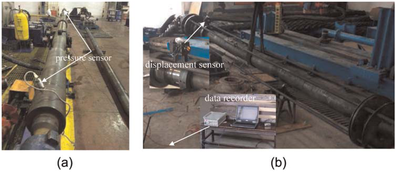
The experimental scene: (a) frequency test and (b) vibration test.
Table 2 is the data of experimental results, and it can be concluded that the antifriction oscillator pressure reduction is 2–3 MPa, and the smaller the static plate diameter is, the bigger the tool pressure reduction will be. The changing frequency of antifriction oscillator is proportional to the flow rate of drilling pump, which is basically consistent with the calculated results. When the displacement of pump is 25 L/s, the antifriction oscillator vibration displacement is 5–15 mm and vibration velocity is waving −0.8 to 0.8 m/s. Moreover, the vibration test results can be seen in Figure 16. Some irregular phenomenon is found in vibration curves, that is, because the antifriction oscillator is installed without level, the support member has an uncertain friction effect. Comparing the results of experimental test and numerical example calculation, the experiment displacement is less than the theoretical calculation, which is related to the friction of supporting part and the smaller test flow compared with the actual flow. Therefore, within the range of experimental error, the measured vibration displacement and velocity changes coincide with the numerical example, which can prove the correctness of the model and analysis method established before.
The experimental data.


The vibration test results: (a) vibration displacement and (b) vibration velocity.
Conclusion
For avoiding large friction between drill string and wellbore or WOB decreasing, a new downhole antifriction oscillator is presented in this article. The results of calculation and experimental test show that the changing frequency of the flow area between dynamic and static valve is proportional to the drilling fluid flow rate, which is determined by the structure parameters.
Moreover, the greater the static valve hole diameter and the input flow rate, the greater the pressure drops, and the pressure drop is 2–3 MPa. The numerical calculation shows that the greater the pressure drop of tools, the greater the total axial force; and the greater the input flow rate, the greater the total axial force.
Through the establishment of vibration analysis model, the results show that the vibration displacement is changing from 1 to 16 mm, and the vibration velocity is changing from −0.8 to 0.8 m/s. Moreover, within the range of experimental error, the measured vibration displacement and velocity changes coincide with the numerical example, which can prove the correctness of the model and analysis method established before.
In the downhole drilling conditions, the periodic axial force produced by the antifriction oscillator can make the drilling tools to have a certain range of vibration during rock breaking process, which can change the friction between the drill string and borehole wall from static to dynamic friction. Therefore, it can improve transmission of the WOB and increase the horizontal drilling footage and ROP. Moreover, the research methods and models can also provide references for new method or tools research of drilling friction reducing or ROP increasing technologies.
Footnotes
Academic Editor: Stephen D Prior
Declaration of conflicting interests
The author(s) declared no potential conflicts of interest with respect to the research, authorship, and/or publication of this article.
Funding
The author(s) disclosed receipt of the following financial support for the research, authorship, and/or publication of this article: This work is supported by Open Fund (OGE201403-05) of Key Laboratory of Oil & Gas Equipment, Ministry of Education (Southwest Petroleum University), National Natural Science Foundation of China (no. 51074202, no. 11102173), and Major Cultivation Foundation of Sichuan Education Department (12ZZ003, no. 667).