
Abstract
The cost and security of ocean drilling are directly related to the efficient exploration and development of ocean resources. The riserless drilling system is usually adopted in the ocean drilling. With the consideration of marine environment load, a dynamic analysis model of drill string in deep-water riserless drilling is established. This model aims to analyze the dynamic characteristics of drill string in the water and down hole during the process of deep-water riserless drilling. The research results are as follows. For the drill string in water, its displacement increase with the increase of ocean current velocity, water depth, rotation speed, and WOB. But the rotation speed and WOB have less influence. The drill string in down hole shows the same pattern. However, the drill string in down hole is only affected near the mud line and the bit, and the rest of the drill string is almost unaffected. In deep-water riserless drilling, stress on the drill string at the wellhead, near the mudline, and at the bottom hole assembly (BHA) is complex. The safety of drill string at these locations should be given great attention.
Keywords
Introduction
The exploration of resources has gradually extended to the deep water with the continuous decrease in land resources. The successful exploration and utilization of deep-water resources have become the focus. However, the exploration and development of deep-water resources still limit by problems related to cost and safety. Ocean drilling refers to drilling, coring, and other operations implemented using drilling ship/platform in deep water. 1 It is the key strategy for exploring geology and resource distribution in deep water. A riserless drilling system is typically adopted in the implementation of ocean drilling technology. 2 During the drilling process, the drill string in down hole is affected by the rock and well wall. Meanwhile, the drill string in water is directly affected by the marine environment load. The load acting on the entire drill string is extremely complex. In this case, the drill string is easy to produce large deformation, fatigue fracture, and so on, seriously threatening the safety of drilling. Therefore, studying the dynamic characteristics of the drill string in deep-water riserless drilling is of highly significant for ensuring the safety of ocean drilling and promoting the efficient exploration and development of ocean resources.
The riserless drilling technology was first proposed and gradually studied during the 1960s. 3 In 2003, a riserless drilling fluid recovery system developed by Norway’s AGR Company was first applied and widely popularized. 4 At first, this riserless drilling fluid recovery technology was only used for oil and gas production in shallow water. After many years of research, a riserless pressure-controlled drilling technology that is suitable for deep and ultra-deep water has been gradually developed. This technology can be applied to deep-water drilling operation over 3000 m. 5 So far, scholars have published many studies on riserless drilling. These studies refer to string safety, well control, temperature distribution, and many other aspects. DeWayne et al. 6 analyzed the characteristics of a periodic vertical vibration load of deep-water running tubular column under the longitudinal movement of drilling platform. Mao et al. 7 proposed a two-phase flow model considering high pressure gas invasion in riserless drilling. They proved that their model can more accurately predict high pressure gas invasion in riserless drilling by reproducing field data and comparing with existing models. Feng et al. 8 analyzed the transient heat problem of circulating fluid in riserless drilling and verified the temperature distribution in riserless drilling. Chagas et al. 9 applied the results of a computational well control simulator using the Driller method to understand the thermodynamic behavior of synthetic drilling fluids, such as n-alkanes and ester based drilling fluids. Xia et al. 10 studied the mechanical characteristics of the drilling fluid return pipeline of deep-water riserless drilling under the movement of the drilling vessel by using finite element analysis software. Their result showed that the bending moment of the return pipeline was large at the suspension joint and the lower seabed pump. Samuel et al. 11 established a predictive mechanical model of hook load and wellhead lateral force by using rigid and soft rope model. They provided a stress calculation method for drill string under the load of an internal drilling fluid and external wave and current.
Many of these studies on riserless drilling are focused on drilling fluid return pipeline or drilling fluid temperature. Only a few research has been done on dynamic characteristics of drill string. Li et al. 12 analyzed the 3D vibration fatigue life of drill string in deep-water riserless drilling on the basis of Miner’s linear cumulative damage law. Li and Collins 13 reported that excessive weight on bit (WOB) may cause the buckling of the drill string at the wellhead when carry out riserless drilling in shallow water. Han et al. 14 developed a mechanical model of drill string in water by considering the working environment of a drill string during deep-water riserless drilling. Niedzwecki and Thampi 15 studied the sensitivity of a long drill string without a riser suspended on a floating vessel to predict upward and downward response. They proposed a general analysis method for various deep-water pipeline system. Gao and Zhang 16 established a design for feeding drill string in deep-water riserless drilling and a strength checking method. They pointed out that deformation and movement were axial and lateral bending deformation and torsional vibration. Chen et al. 17 performed a torque mechanical experiment on drill string in riserless drilling. They found that the friction generated in the tangential direction when the drill string is rotating in water produces additional torque in the drill string. Most of these studies focus on drill string in shallow water. Even in the study of deep water drill string, only the drill string in water is concerned. Moreover, most of these studies use the lumped parameter method or finite element software, and only a few studies use the finite element method.
In summary, the research on the dynamic characteristics of drill string under marine environmental load during riserless ocean drilling is still rare. The influence law of water depth, marine environmental load and other factors remain unclear. Therefore, in consideration of marine environment load, a finite element model of drill string in deep-water riserless drilling is established to analyze the dynamic characteristics of drill string in water and down hole during the process of deep-water riserless drilling. This model is expected to provide theoretical guidance for ensuring the safety of drill string in deep-water riserless drilling.
Dynamic model of drill string in deep-water riserless drilling
Floating drilling platforms are commonly used in ocean drilling. 18 As shown in Figure 1, floating drilling platform includes semi-submersible drilling platform and drilling ship, has self-navigation ability, with anchor cable or dynamic positioning system positioning on the sea operation of the ship drilling device. The platform is positioned by mooring or dynamic positioning system. The buoyancy drilling unit floats on the sea surface and is vulnerable to waves. In the floating state of the sea, due to the action of wind and waves will produce heave, sway, drift and other movements. 19 As shown in the following figure, the drillship/platform first sails to a predetermined position to anchor in riserless drilling. Then the subsea suction module and anchoring device should be installed. After that, the drill string will be lowered down to dock with subsea suction module. Next, the submarine pump should be fixed on the anchoring device. Finally, after the subsea line installed, the riserless drilling system can begin drilling.
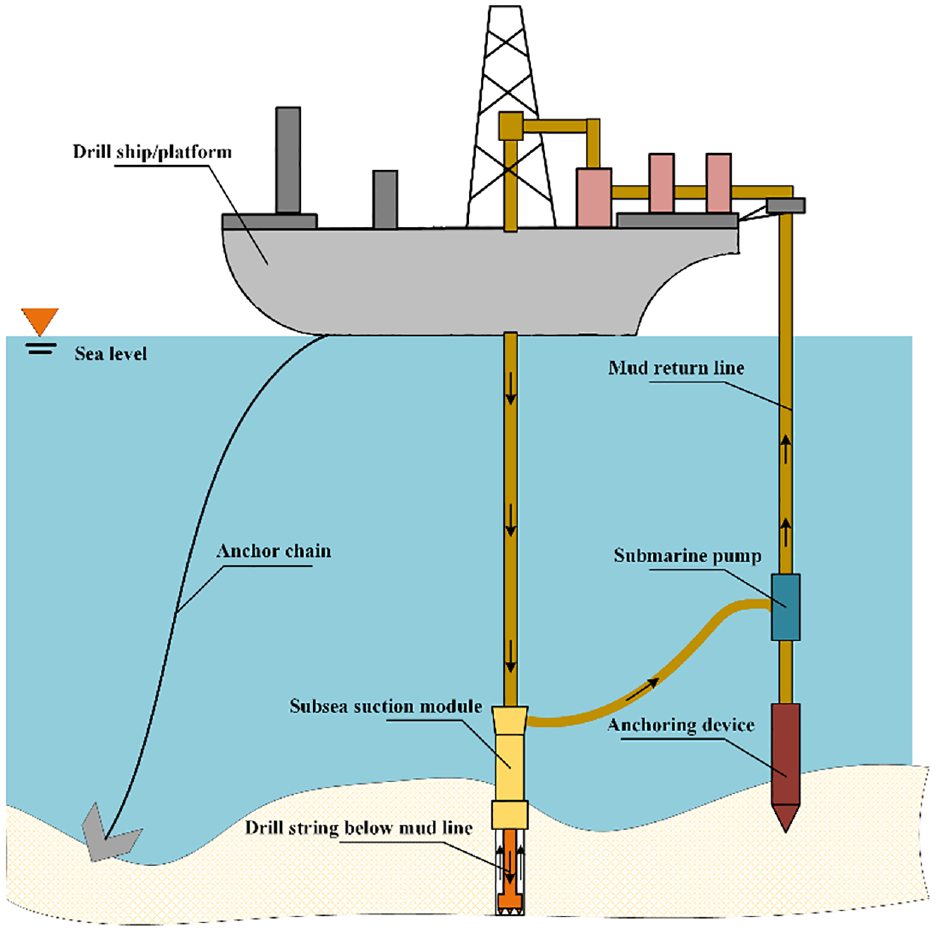
Riserless drilling operation diagram.
Ocean drilling is performed using riserless drilling technology. The stress characteristics of drill string during ocean drilling are evidently different from those during land drilling. The bottom hole assembly (BHA) is affected by WOB and torque on bit (TOB). The drill string will collide with well wall when the bending deformation of the drill string exceeds the clearance between drill pipe and borehole. Moreover, the drill string is constrained by the well wall. As shown in Figure 2, in addition to lifting force of the hook and torque of the rotary table, the drill string in water also bears the marine environment load.

Physical model diagram of drill string in deep-water riserless drilling.
Establishment of dynamic model
In the current study, the following hypotheses are presented when establishing the dynamic model of drill string. (i) The borehole is considered a smooth and equal section circle. (ii) The drill string is considered as 3D elastic beams with uniform material and geometric characteristics. Its deformation is within the elastic range. (iii) Connecting threads and joints between drill string are disregarded.
As shown in Figure 3, the drill string can be discretized into some bi-node beam elements. Each node has 6°, including three translation amounts, two lateral rotation angles, and one torsional angle. The movement of drill string can be expressed by the displacement vector of the beam element nodes, as follows:


Diagram of beam element node division.
The Lagrange equation 20 that controls the movement of drill string can be expressed as:

where T refers to kinetic energy, V refers to potential energy,
The expression for the total kinetic energy of the beam unit21,22 is

where
The expression for the total potential energy of the beam unit23,24 is

where E refers to the elastic modulus of drill string, in Pa; and G refers to the shear modulus of drill string, in Pa. In equation (4), the linear stiffness matrix can be derived from the first four items, while the nonlinear stiffness matrix that corresponds to the bending and axial deformations of drill string can be derived from items 5–9. Moreover, the nonlinear stiffness matrix that corresponds to the torsional and bending deformations of drill string can be derived from the last three items.
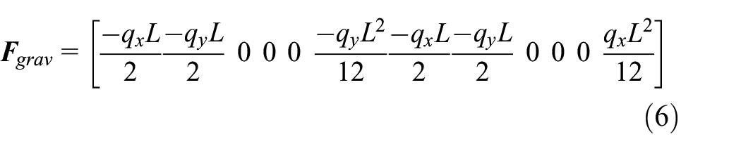
The nodes of a beam element are subjected to two types of external forces: centrifugal force and gravity. The gravitational components of the beam element on x, y, and z can be expressed as:

where q refers to the equivalent gravity of a 1 m drill string, in N/m; and
The centrifugal force of the beam element generated by the autorotation on x, y, and z can be expressed as:

where

By substituting equations (3), (4), (6), and (8) into equation (2), the following equation can be obtained:

where
Boundary conditions
Constraints of the well wall
In the practical drilling process, the movement of the drill string is constrained by the rotary table. Its upper end is hinged at the center of the borehole to bear torque and tension. The drill string is subjected to reverse torque and the exciting force from rock, and its lateral displacement is constrained. Moreover, the gap between the drill string and the well wall is small, and the radial displacement of the drill string is constrained. Figure 4 illustrates the contact between the drill string and the borehole. The drill string will subject to normal force, tangential friction, and additional friction torque. Once the elastic deformation of the wellbore is resumed, the drill string will bounce back and the node will regain freedom. The normal force FN can be expressed25,26 as

where dw refers to the diameter of the wellbore, in m; do refers to the outer diameter of the drill string, in m; vr refers to the radial velocity of the drill string, in m/s; ur refers to the radial displacement of the drill string, in m; kh refers to the stiffness of the wellbore, in N/m; and v1 and v2 refer to the speed before and after node collision, respectively, in m/s.

Contact diagram between drill string and well wall.
Tangential friction Ff and friction torque Tf can be expressed as

where

where uk and us refer to dynamic and static friction coefficients, respectively; de refers to the attenuation coefficient; and vs refers to the slip ratio.
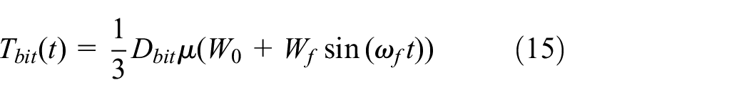
Interaction model between bit and rock
Due to the collision between the bit and rock, the change of weight on bit (

where

where
where
Calculation of marine environmental load
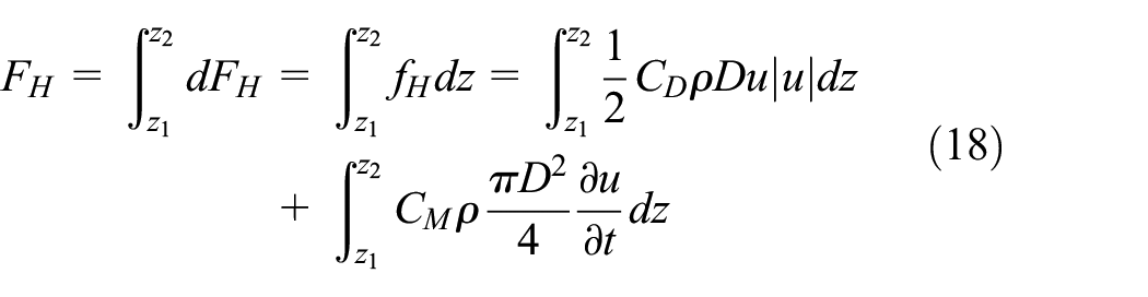
The effect of marine environmental load on the drill string in water should also be considered. In the current study, wave force is calculated by Morison equation, 29 which includes horizontal drag and inertial forces. Horizontal drag resistance is generated by the wave flowing through the drill string, while inertial force is caused by the acceleration of water. Wave force can be expressed by the following formula:

where
The coordinate system is shown in Figure 5, and the horizontal wave force acting on the dz segment of a single cylinder is

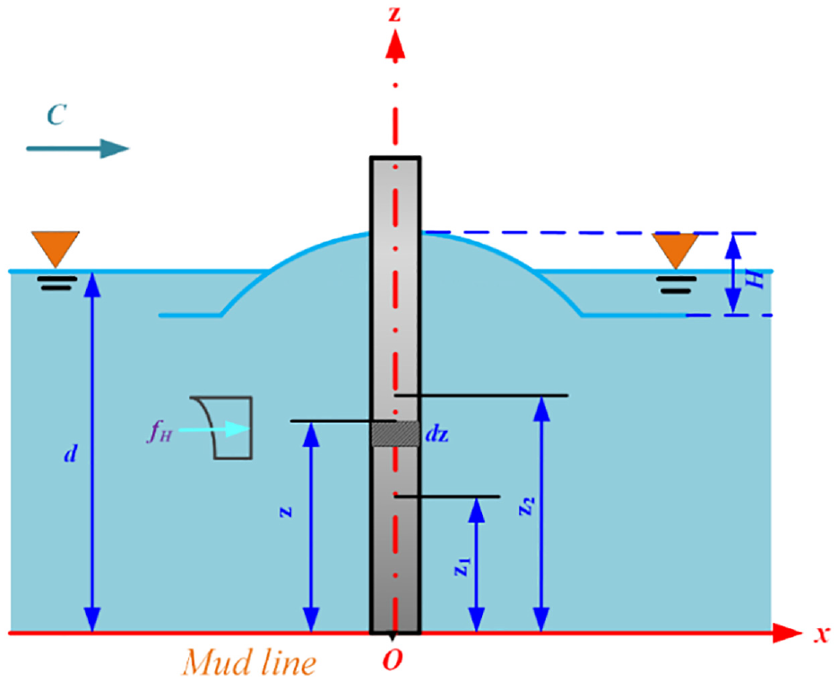
Schematic diagram of Marine environmental load on drill string.
In order to find the horizontal wave force acting on a column section (z2–z1), equation (18) can be integrated from z1–z2:
When, z1 = 0, z2 = d + η, the total horizontal wave force on the whole cylinder is

Similarly, the total horizontal wave moment on the whole cylinder (calculated with respect to the seabed) can be obtained as:

The horizontal velocity and acceleration of wave particles are calculated using Airy wave formula.


where
The upper drill string is not constrained by the well wall. Therefore, the wave forces and torques obtained by equations (19) and (20) will serve as boundary conditions for the upper drill string. For the drag force coefficient CD and mass coefficient CM used in the calculation of ocean load above, different countries have different recommended values. Table 1 shows some of the recommendations.
Recommended values for CD and CM in national codes.

Model solution
From the aforementioned conditions, the dynamic model of drill string in deep-water riserless drilling is a highly complex nonlinear coupling model. Thus, it should be solved using a numerical method. In this study, the model is solved using the Newmark-β method. The major process is illustrated in Figure 6.

Flowchart of the finite element model.
Newmark-β method is a common method to solve finite element model. The Newmark-β method is a progressive integration scheme proposed by Newmark in 1959. Its basic assumptions are:


where,
In this case, take


Considering the dynamic equation at the moment

Substituting equations (25) and (26) into (27), we get the equation of

Where:

Solving the equation (28), we can get
The step-by-step solution process of Newmark-β method is as follows:
A. Preliminary calculation.
(1) Form stiffness matrix
(2) Given initial value
(3) Select the time step


(4) Formed the effective stiffness matrix
(5) The triangular decomposition of
B. Calculate for each time step.
(1) Calculate the payload at time

(2) Calculate acceleration and velocity at time

Analysis of dynamic characteristics of drill string in deep-water riserless drilling
A simulation is conducted by using the basic parameters of riserless drilling in the South China Sea as an example. The BHA, drilling parameters, and marine environmental loads are provided in Table 2. Simulation time is 5 s. The simulation aims to analyze the dynamic characteristics of drill string in water and down hole under different bit pressures, rotation speed, water depths, and ocean current velocity.
Simulation parameters.

Dynamic analysis of drill string in water
Effect of current velocity on the dynamic characteristics of drill string in water
Figure 7 depicts lateral displacement and stress distribution of the drill string in water under different current velocity. As shown in Figure 7(a), the strain of drill string initially increases and then decreases from the water surface to the mudline. The lateral displacement of drill string reaches the highest at a water depth of around 1300 m. If the current velocity is larger, then lateral displacement of drill string is greater. When the current velocity is 1.21 m/s, the maximum lateral displacement of drill string can reach about 25 m. The increasing velocity profile directly increases the current force acting on drill string, consequently increasing the deformation of drill string. However, as shown in Figure 7(b), the stress of drill string gradually decreases, and the maximum stress occurs near the wellhead. Current velocity shows little effect on stress distribution of drill string. The maximum stress in drill string can reach up to 300 MPa. In riserless drilling, stress on drill string near the wellhead is considerable. Therefore, the drill string near the wellhead exists a risk of failure, which should be given more attention.

Lateral displacement and stress distribution of drill string in water under different current velocity: (a) lateral displacement (b) stress distribution.
The drill string in water is mainly subjected to axial tension and lateral load, in which the lateral load mainly refers to the drag force generated by current flow. It can be seen from Formula 16 that the drag force at each position of drill string is mainly affected by current velocity. With the increase of current velocity, the drag force of drill string at each position in water will be increased, and the lateral load of drill string in water will be significantly increased. In the riserless drilling operation, in order to prevent the drill string from deformation failure, it is suggested to increase the thickness of drill string wall or choose a higher strength steel. These methods can enhance its bending performance and reduce the risk of lateral deformation and drill string failure.
Effect of WOB on the dynamic characteristics of drill string in water
Figure 8 presents lateral displacement and stress distribution of drill string in water under different WOB. As shown in Figure 8(a), if WOB is higher, then the lateral displacement of drill string is larger. When WOB reaches 100 kN, the lateral displacement of drill string can reach the highest, around 16 m. However, as depicted in Figure 8(b), if the WOB is lower, the equivalent stress of drill string is larger. When WOB is 60 kN, the maximum stress of drill string can reach 290 MPa. The cause of this phenomenon is that increasing WOB will lower the axial tension of drill string. Meanwhile, decreasing axial tension is equivalent to lowering the flexural stiffness of drill string, consequently increasing the lateral displacement and bending moment of drill string. However, reducing the overall axial force of drill string will significantly reduce the stress of drill string. Therefore, if WOB is greater, then the maximum stress of drill string in water becomes smaller. This result shows that WOB is properly increased when the lateral displacement of drill string is not large during riserless drilling. Therefore, properly increased WOB will not lead to the failure of drill string in water.

Lateral displacement and stress distribution of drill string in water under different WOB: (a) lateral displacement and (b) stress distribution.
Effect of rotation speed on the dynamic characteristics of drill string in water
Figure 9 present the lateral displacement and stress distribution of drill string in water under different rotation speed. As shown in Figure 9(a), if rotation speed is higher, then the lateral displacement of drill string is greater. However, when rotation speed is 50 and 70 r/min, increasing rotation speed exerts little effect on lateral displacement of drill string. After rotation speed reaches 90 r/min, increasing it exhibits considerable effect on lateral displacement of drill string. Moreover, as shown in Figure 9(b), rotation speed has little effect on the stress distribution of drill string. The drill string subject to centrifugal force and damping force from water and drilling fluid because the drill string rotates in seawater and drilling fluid. Increasing rotation speed simultaneously increases the centrifugal and damping forces on the drill string. The centrifugal force enhances the vibration of drill string, leading to an increase in the lateral displacement of drill string. Meanwhile, the damping force inhibits the vibration of drill string. The difference between damping and centrifugal forces is small when rotation speed is low. Thus, increasing the rotation speed exerts little effect on the lateral displacement of drill string. The centrifugal force is greater than the damping force when the rotation speed is high. Hence, the lateral displacement of drill string increases more evidently with an increase in rotation speed.

Lateral displacement and stress distribution of drill string in water under different rotation speed: (a) lateral displacement and (b) stress distribution.
Effect of water depth on the dynamic characteristics of drill string in water
Figure 10 presents the lateral displacement and stress distribution of drill string in water under different water depth. As shown in Figure 10(a), the lateral displacement of drill string is greater when water depth is deeper. The maximum lateral displacement of drill string is only about 1 m when water depth is 500 m. The maximum lateral displacement of drill string can reach about 17 m when water depth is 3000 m. The reason for these results is as follows. If water depth is deeper, the drill string is longer, and structural flexibility is stronger. Therefore, flexural capacity is weaker. Moreover, the marine environmental load on drill string is greater when the water depth is deeper. Therefore, if the water depth is deeper, then the bending deformation of drill string in water is greater. As shown in Figure 10(b), stress on the drill string is greater when the axial load and bending moment of drill string are larger. Consequently, squeeze pressure on the drill string by seawater is also higher.

Lateral displacement and stress distribution of drill string in water under different water depth: (a) lateral displacement and (b) stress distribution.
Dynamic analysis of drill string in down hole
Effect of current velocity on the dynamic characteristics of drill string in down hole
Figures 11 and 12 present the dynamic characteristics of drill string in down hole under different current velocity. The Figure 11 depicts the trajectory of drill string below the mud line. As shown in Figure 11, a more disordered drill string track close to the bit indicates stronger vibration. Meanwhile, the trajectory of drill string near the mud line also shows complicatedly due to the disturbance of upper drill string. However, the current velocity exerts little effect on the bottom drill string for the entire lower drill string. The movement track, equivalent stress, and lateral displacement of drill string near the bit change slightly under different current velocity. The drill string near the mudline is evidently affected by current velocity. The lateral displacement of drill string at this position becomes more serious with the increase of current velocity. The current force on drill string in water is inceasing with the increase of current velocity, affecting the drill string near the mudline. The impact of ocean current on drill string is diminishing from the top to down. It’s basically not affected by the current velocity, when get to the BHA.

Drill string movement track under different current velocity.

Displacement and stress distribution of drill string in down hole under different current velocity: (a) stress distribution and (b) lateral displacement.
Effect of WOB on the dynamic characteristics of drill string in down hole
Figures 13 and 14 present the dynamic characteristics of drill string in down hole under different WOB. Figure 13 depicts the movement track of drill string under different WOB. The Figure 13 shows the movement track of drill string at three different positions below the mud line. The recording spot of drill string is indicated by a red square on the left side of Figure 13. The top spot is near the mud line, while the bottom spot is on the BHA. Meanwhile, the Figure 13 also shows the trajectory of each point at different WOB. The movement track of drill string near the bit becomes more complex with the increase in WOB. When WOB reaches 100 kN, the movement track nearly fills the whole wellbore. As shown in Figure 13, the equivalent stress of drill string near the bit (about 200 m) increases continuously with the increase in WOB, whereas the equivalent stress of drill string more than 200 m away from bit is decreasing continuously. This phenomenon is caused by the tension of drill string equivalent point. If WOB is higher, axial tension and equivalent stress on drill string are also smaller. In addition, the lateral displacement of drill string near the bit becomes more serious with the increase of WOB, and the lateral displacement of drill string near the mudline is also greater. Tension on top is reduced while WOB is increased, leading to a decrease in the axial tension and bending resistance of drill string in water, finally aggravating the lateral displacement of drill string at the mudline.

Drill string movement track under different WOB.
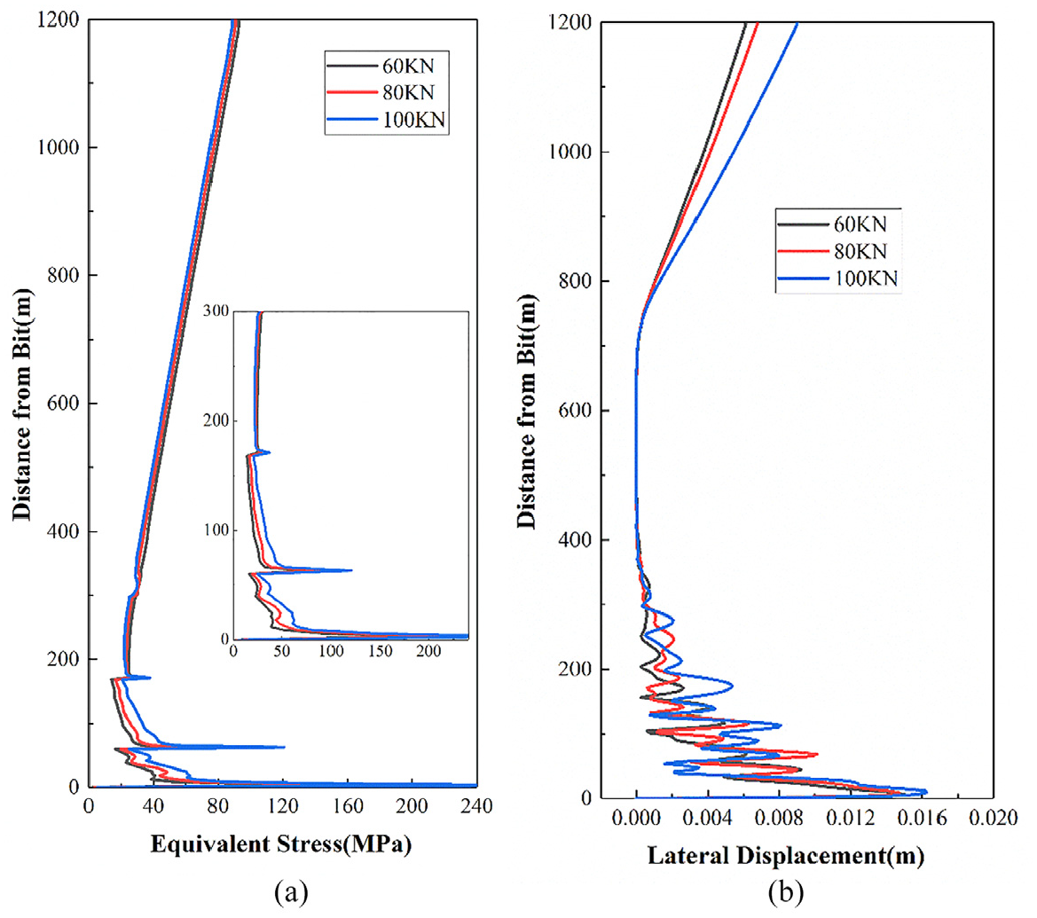
Displacement and stress distribution of drill string in down hole under different WOB: (a) stress distribution and (b) lateral displacement.
Effect of rotation speed on the dynamic characteristics of drill string in down hole
Figures 15 and 16 present the dynamic characteristics of drill string near the bit under different rotation speed. Rotation speed exerts an effect on the drill string near the bit (within 200 m of the bit). The movement track of the drill string 9 m away from the bit becomes more complex with the increase of rotation speed. It is no longer similar to a ring, but instead, collides back and forth in the wellbore. Motion trajectory fills the whole wellbore. More severe collision increases the equivalent stress of drill string near the bit. With the given BHA, the equivalent stress of drill string near the bit is much lower than its yield strength when rotation speed is lower than 90 r/min. So the drill string is free from failure risk.

Drill string movement track under different rotation speed.

Displacement and stress distribution of drill string in down hole under different rotation speed: (a) stress distribution and (b) lateral displacement.
Effect of water depth on the dynamic characteristics of drill string in down hole
Figures 17 and 18 show the dynamic characteristics of drill string in down hole under different water depth. These figures show that the movement track of drill string near the bit (9 m from the bit) changes slightly with the increase of water depth. No evident change occurs in the lateral strain of drill string near the bit and the equivalent stress of drill string in down hole. Those indicate that water depth exerts little effect on the dynamic characteristics of drill string near the bit. In addition, the lateral displacement of drill string near mudline increases with the increase of water depth. The reason for such finding is that the increase of water depth has weaken the bending resistance of drill string in water. The weaken bending resistance of drill string in water has strengthened the lateral displacement of whole drill string, extremely aggravating the drill string near mudline.

Drill string movement track under different water depth.

Displacement and stress distribution of drill string in down hole under different seawater depth: (a) stress distribution and (b) lateral displacement.
Conclusions
(1) Considering the marine environment load, a dynamic model of drill string in deep-water riserless drilling is established in this study using the finite element method. The dynamic model can use to analyze the dynamic characteristics of drill string in water and down hole during the process of deep-water riserless drilling under different work conditions.
(2) For the drill string in water, its lateral displacement and stress increase with the increase of ocean current velocity, WOB, rotation speed, and water depth, while rotation speed exerts little effect on dynamic and stress characteristics of drill string. The drill string in down hole should be given great attention when WOB increase in deep-water riserless drilling.
(3) For the drill string in down hole, its lateral displacement near the mudline increases with the increase of ocean current velocity, WOB, rotation speed, and water depth. However, the effect of rotation speed on the dynamic and stress characteristics of drill string is insignificant.
(4) On the basis of preceding studies, stress of drill string at the wellhead, near the mudline, and BHA is complex during deep-water riserless drilling. The safety of drill string at these locations should be given great attention.
Footnotes
Handling Editor: Chenhui Liang
Declaration of conflicting interests
The author(s) declared no potential conflicts of interest with respect to the research, authorship, and/or publication of this article.
Funding
The author(s) disclosed receipt of the following financial support for the research, authorship, and/or publication of this article: The authors gratefully acknowledge the financial support of the Key Special Project for Introduced Talents Team of Southern Marine Science and Engineering Guangdong Laboratory (Guangzhou) (GML2019ZD0504), The National Key Research and Development Program of China (No.2021YFC2800801), Research on borehole stability and safe drilling technology of ultra-deep Wells in Wenchang Oilfield Group (CCL2022RCPS0139PSN01) and Province Marine Economic Development Special Fund Project: Drillship Design and Construction Key Technology Research ([2021] No. 043).