
Abstract
The cavitation performance of an axial flow pump with inlet guide vanes for different flow rates is studied in this article. The effects of inlet guide vanes on pump hydraulic performance and cavitation are investigated, where the total vapor fraction of impeller zone (Ftv) is calculated to predict the critical net positive suction head, which is compared with that predicted by efficiency criterion for different flow rates. The influences of the development of cavitation on internal flow in impeller zone are also investigated. The results obtained show that the cavitation performance of axial flow pump can be improved at off-design flow conditions by adjusting angles of inlet guide vanes to positive values at low flow rates and by regulating angles of inlet guide vanes to negative values at high flow rates. As the net positive suction head decreases, the vapor fraction first increases slowly and then increases greatly, clearly presenting cavitation process from inception to full development, which can be used to predict the required net positive suction head. When net positive suction head decreases to the value around required net positive suction head, the cavitation zone from tip of blade suction side close to leading edge and the cavitation zone from hub part of the blade suction side connect together. After the connection, the cavitation zones have great influence on the velocity flow, leading to the decrease in pump performance.
Introduction
The axial flow pump is widely applied in large hydraulic engineering, especially in the fields of drainage, irrigation, and water supply. Cavitation, known as a very important physical phenomenon in the pump, can be found when the tiny nuclei grow into observable bubbles. Initially, the nucleation occurs through the homogeneous nucleation, heterogeneous nucleation, stable microbubbles in liquid, and radiation from outside. 1 Cavitation begins to occur when the local pressure reaches the liquid–vapor pressure at the local temperature in the presence of nuclei. Then some negative effects may be caused by its unsteady and erosive characteristics, such as noise, vibration, performance reduction, and erosion.2–5 The occurrences of these negative effects are not at the same time but step by step with the development of cavitation. Therefore, it is very important to understand the inception and development of cavitation in the pump in order to prevent cavitation.
The net positive suction head (NPSH) is the parameter of pump cavitation performance. In pump system, the energy can be lost when fluid travels through pipes, valves, and so on. Normally, the minimum energy of fluid at pump inlet where the cavitation is going to occur is called the available NPSH (NPSHa). For pump design, the required NPSH (NPSHr) is used that is usually experimentally measured by NPSH for 3% head drop (NPSHhead,3%) or NPSH for 1% efficiency drop (NPSHeff.,1%) and the NPSHa should be greater than NPSHr in order to avoid pump cavitation. 3
Many researchers have predicted the inception and development of cavitation through the experiments and numerical simulations. The process of cavitation is usually determined by two criterions (NPSHhead,3% and NPSHeff.,1%). Hosien and Selim 6 experimentally showed that the visual incipient of cavitation in the pump existed long before drop in pump head occurred, although NPSHhead,3% was adopted to predict the NPSHr.7–9 Avellan 10 and Zhang and Chen 11 presented the influences of cavitation development on fluid machinery efficiency by using NPSHeff.,1% to predict the critical cavitation. Due to the unsteady behavior of cavitation, the measurement of noise and vibration is another useful method to identify the process of cavitation. Christopher and Kumaraswamy 3 experimentally investigated the radial flow pump with three different leading edge (LE) profiles of the vane under cavitating case by measurement of noise and vibration. They revealed that the ways by monitoring noise signal and vibration signal were better to sense the NPSHr than ordinary methods. In addition, Buckland et al. 12 introduced a cavitation detection model to indicate any cavitating blade elements, which was a useful addition to the blade element momentum theory for modeling tidal stream turbines. In this article, the numerical value of total vapor fraction of impeller zone is studied to determine the NPSHr compared with the data predicted by NPSHeff.,1%.
The performances of axial flow pump including efficiency and cavitation decrease when the pump operates under off-design flow conditions. The adjustable inlet guide vane (IGV) is considered as one of the effective ways to improve the performances of fluid machineries such as compressor, fan, and centrifugal pump.13–17 Zhou et al. 13 showed that the IGVs could improve compressor performance and could be regulated to suitable angle to avoid unsteady vibrations at off-design conditions simultaneously. Shaw et al. 15 thought that the variable IGVs could improve the performance and stability margin of fan by controlling the inlet flow distortion. Tan et al. 17 found that pre-whirl regulation of IGVs could enhance the peak value of efficiency in centrifugal pump and thought that the cavitation performance of centrifugal pump with IGVs was worse than that without IGVs but this influence was limit. Although the effects of IGVs on centrifugal pump have been studied, the effects of IGVs on axial flow pump or on the special flow phenomena in the pump including cavitation are not yet fully understood.
The detailed characteristics of cavitating flow are also necessary to analysis, which can reveal the formation of cavitation and its influences.18–25 Park and Rhee 18 analyzed the three-dimensional cloud cavitating flow around a twisted hydrofoil and found a re-entrant jet and a side entrant jet in terms of the cavity shedding cycles. Ji et al. 19 numerically investigated the structure of the cavitating flow around a twisted hydrofoil and found that both vortex production and boundary layer thickness were affected by cavitation. Zhang and Chen 11 numerically invested the cavitating flow within a slanted axial flow pump and they indicated that the instability of cavitating flow on the blade suction side had great influences on pump performance.
In this article, the effects of IGVs on performance, especially for cavitation performance, of axial flow pump for different flow rates are investigated. A parameter (Ftv) is calculated to describe the process of cavitation when NPSH decreases, which can be used to predict the NPSHr. Moreover, the internal flow in the pump at different stages of cavitation is also analyzed.
Numerical methods
Governing equations
When the pressure drops to vapor pressure, the liquid begins to vaporize and the vapor flows mixing with liquid. By using the simplification of no slip velocity between two phases, the cavitating flow fluid can be considered as a homogenous flow. The continuity and momentum equations for the incompressible mixture flow are shown as


The governing equations are solved by the shear stress transport (SST)

In the process of cavitation, the liquid–vapor mass transfer (evaporation and condensation) is governed by the vapor transport equation

The Zwart–Gerber–Belamri model 28 is chosen for the expression of the rates of mass exchange, because it is robust and converges quickly. This model is based on the assumption that all the bubbles in cavitation have the same size and the equations are shown as follows: 29
If

If
In ANSYS FLUENT 14.5, the mentioned coefficients above are set as follows:
Computational domain and boundary conditions
The pump parameters are listed in Table 1. The computational domain is the flow passage from the inlet to the outlet, including inlet straight pipe, IGVs, impeller, exit guide vane, 60° bend, and outlet straight pipe as shown in Figure 1. The straight pipe lengths before and after the pump are, respectively, 7D and 5D in order to ensure the flow field in the pump is independent from the boundary conditions. The head of the pump is determined by simulating the suction and delivery total pressures, which are, respectively, located at the cross sections in front of the IGVs and behind the bend. The cross section in front of the IGVs is also used for calculating the NPSH. The hexahedral meshing scheme is used for the whole computational domain. In consideration of the highly distorted shape of the impeller, the O-grid is specially used to surround the blades and vanes as shown in Figure 2, where the mesh for the tip clearance is refined. It is defined that when the direction of velocity along IGVs is axial, the angle of IGVs is 0°, and when the direction of tangential velocity component induced by adjusting the angle of IGVs is consistent with the direction of impeller rotation, the angle is positive value and conversely, the angle is negative value. 13 In this article, the angles of the IGVs are chosen as −10°, 0°, and 10°.
Parameters of the research model.

IGV: inlet guide vane.

Sketch map of the computational domain.

Mesh surface at impeller and IGVs.
The multiple reference frame approach is used to solve the rotor–stator interaction problem in domain, with a moving reference frame for the impeller region and a stationary frame for the rest. The mass flow rate is defined at the inlet and static pressure at the outlet. No-slip conditions are applied to the whole wall boundary. In order to obtain a converged solution, the single-phase liquid flow is computed first and then the cavitation model is enabled.
Convergence validation
The grid independence is conducted with three grid numbers at the design flow rate under both non-cavitation and great cavitation conditions. The NPSH is used as the parameter of pump cavitation, which is defined as
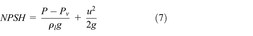
in which P and u are, respectively, the absolute static pressure and velocity calculated from the surface integration of these profiles at the cross section in front of the IGVs.
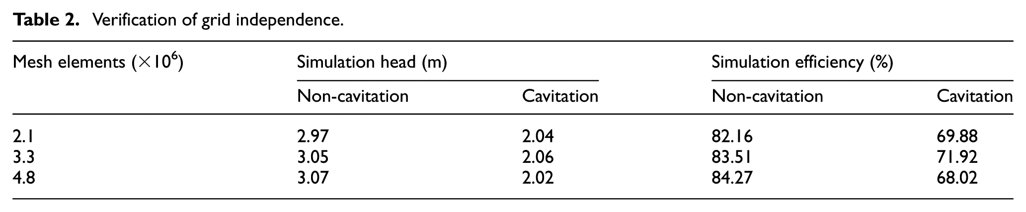
The calculated results, shown in Table 2, demonstrate that the numerical discrepancies of head and efficiency values under different cavitation conditions for three grid numbers are very small, respectively, implying the mesh converged. Thus, the second grid number about 3.3 million is preferable, the wall Y+ values of which are mostly between 30 and 300, which are reasonable to simulate the fully developed turbulent flow near the wall boundary layer.
Verification of grid independence.
Results and discussion
The head as a function of NPSH at the design flow rate for various angles of IGVs is displayed in Figure 3. When the angle of IGVs is 0°, the head slightly reduces in comparison with that without IGVs due to the additional hydraulic loss caused by the IGVs. The head increases for −10° of IGVs while it decreases for 10°, which is consistent with the previous result. 17
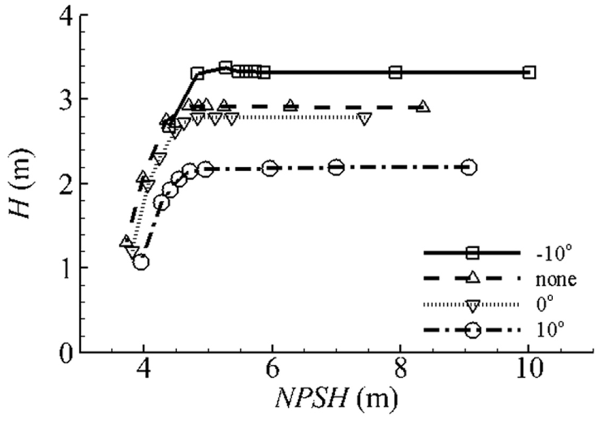
Numerical head versus NPSH for various angles of IGVs at the design flow rate.
For all angles of IGVs, when NPSH begins to decrease, the head first keeps constant. When NPSH continuously decreases to value around the NPSHr, the head slightly increases for −10° of IGVs while it decreases for 0° and 10°. This phenomenon is caused by the variation in the incidence angle at impeller inlet. The incidence angles are almost 0° at design flow condition without IGVs and 0°. For −10°, the corresponding incidence angle increases at the convex side of the hydrofoil in the meridional plane of impeller, resulting in the inception of cavitation on blade suction side. The cavitation can make slightly blockage of the flow passage leading to velocity increase, where the circulation in reality can be treated as increased and then the lift coefficient is increased, which can make the head higher. 30 For 10° of IGVs, the corresponding incidence angle increases at the concave side of the hydrofoil in the meridional plane of impeller, resulting in the inception of cavitation on blade pressure side, and the lift coefficient is decreased, which can make the head fall. When NPSH decreases further, the heads fall greatly and the cavitation at this stage is strong, which produces heavy damage to blade.
The efficiency as a function of NPSH at the design flow rate for various angles of IGVs in Figure 4 is almost the same as that for head, but the efficiency for various angles of IGVs is smaller than that without IGVs because of more hydraulic losses caused by the IGVs.

Numerical efficiency versus NPSH for various angles of IGVs at the design flow rate.
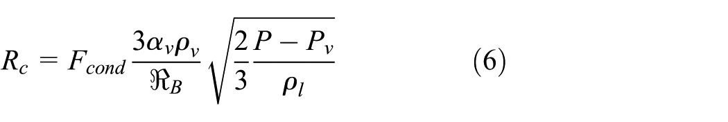
In order to quantitatively analyze the cavitation in pump, a parameter (Ftv) is used, which is defined as

The vapor fraction as a function of NPSH for variable angles of IGVs is displayed in Figure 5. For every angle of IGVs at different flow rates, the vapor fraction first remains unchanged, second increases slowly, and finally increases greatly as NPSH decreases, which is relative to the inception and development of cavitation. Figure 5(a) displays that the moment on the rapid growth of vapor fraction for −10° of IGVs is earlier than that for 10° at the low flow rate, which means that adjusting the angle of IGVs to negative value can make the inception of cavitation early. The situation at the design flow rate is the same as that at the low flow rate as shown in Figure 5(b). On the contrary, the early inception of cavitation at the high flow rate is at 10° of IGVs as shown in Figure 5(c). Figure 5(d) shows that the NPSHr decreases as the angle of IGVs increases at the design flow rate and at the low flow rate, while it decreases as the angle of IGVs decreases at the high flow rate. Therefore, the cavitation performance of axial flow pump can be improved by regulating the angles of IGVs to positive values for low flow rates and by regulating the angles of IGVs to negative values for high flow rates.

Total vapor fraction versus NPSH for various angles of IGVs: (a) 315 L/s, (b) 370 L/s, (c) 415 L/s, and (d) numerical NPSHr versus flow rate for various angles of IGVs and non-IGVs.
This regulation can be explained by the velocity triangle at impeller inlet displayed in Figure 6. Under the design flow condition, it is assumed that vm1 is equal to v1 for 0° of the IGVs and that the incidence angle is 0, where β is consistent with the blade setting angle. When the flow rate decreases, vm1 reduces to

Sketch map of the inlet velocity triangle.
The vapor fraction as a function of NPSH for different flow rates without IGVs is displayed in Figure 7. As NPSH decreases, the regularities of vapor fraction for all flow rates are the same, the curves of which can be fitted with power function like

Total vapor fraction versus NPSH for different flow rates without IGVs.
Comparison of NPSHr between experiment and simulation.
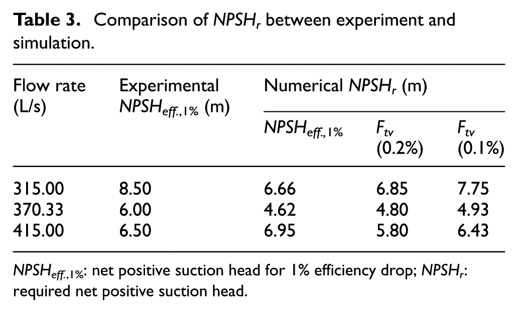
NPSHeff. ,1%: net positive suction head for 1% efficiency drop; NPSHr: required net positive suction head.
Figure 8 displays the distributions of volume fraction of vapor for four cases labeled in Figure 7, which represent that the Ftv are separately 0.00%, 0.02%, 0.20%, and 1.22% from case 1 to case 4. There is no vapor in Figure 8(a) meaning no production of cavitation. Figure 8(b) has zones with small volume fraction, and cavitation can be assumed to occur at this stage. The places of cavitation are first located at tip side close to the inlet and the middle position of the blade suction side because of the low local pressure at these zones. However, the volume fraction of vapor is too small to change the head and efficiency. In addition, the cavitation zones show asymmetry due to the asymmetry three-dimensional geometry of 60° bend. Figure 8(c) displays the contour of volume fraction of vapor when Ftv is 0.2%, where almost half area of blade suction side has been taken up by the cavitation zone and the head and efficiency have been changed. In addition, Figure 8(b) and (c) show that as the pressure decreases, both cavitation zone from the blade tip and the cavitation zone from the hub part gradually expand and finally connect together around the NPSHr. It is notable that when these cavitation zones link together, the Ftv increases to 0.2%, which implies that the connection of the cavitation zones may be used to illustrate the NPSHr. After the connection, the cavitation zones have great influence on the flow field, leading to a decrease in the pump performance. Figure 8(d) displays the contour of volume fraction of vapor when Ftv is 1.22%, where the volume fraction of vapor has increased greatly, which means the cavitation has greatly developed and the cavitation zone takes most part in the blade suction side close to trailing edge (TE).

Volume fraction of vapor around the blade suction side under design point: (a) case 1, (b) case 2, (c) case 3, and (d) case 4.
Conclusion
The cavitation performance of axial flow pump with the IGVs at different flow rates has been studied using computational fluid dynamics (CFD) method. Compared with the experimental data, the simulation results are credible. The cavitation performance of axial flow pump can be improved by adjusting the angle of IGVs to positive value at the low flow rate and by adjusting the angle of IGVs to negative value at the high flow rate, but at the cost of efficiency decreases due to more hydraulic losses induced by the implementation of IGVs.
As the NPSH decreases, the Ftv first increases slowly and then increases greatly, which clearly presents cavitation process from inception to full development. It is found that the Ftv is suitable to be used to predict the NPSHr in comparison with the efficiency criterion. Furthermore, the connection between the cavitation zone from tip side close to LE and the cavitation zone from hub part of the suction side is a very important signal to indicate the great deterioration of pump performance.
Footnotes
Appendix 1
Academic Editor: Moran Wang
Declaration of conflicting interests
The author(s) declared no potential conflicts of interest with respect to the research, authorship, and/or publication of this article.
Funding
The author(s) disclosed receipt of the following financial support for the research, authorship, and/or publication of this article: This work was supported by the Key Projects in the National Science & Technology Pillar Program during the 12th Five-Year Plan Period (grant no. 2012BAD08B03) and the National Natural Science Foundation of China (grant no. 51422906).