
Abstract
In practical engineering, the container building usually has an opening and stiffening process to meet the requirements of architectural design. So, the stiffness of the container with holes has been studied and stiffening member has been considered in the process of container stiffness enhancement. First, based on the paper “Theoretical and experimental studies on in-plane stiffness of integrated container structure,” the stiffness of corrugated sheet with window, door, and combined window has been derived and then the stiffness of corrugated sheet with above-mentioned holes has been derived. Thus, through stiffness distribution between frame and corrugated sheet, the stiffness of container with holes has been derived. Second, through finite element software of Abaqus, full-size container model with holes has been established and combined with stiffening members. Through simulation, the load–displacement curve has been got and then compared with theoretical analysis. Finally, through full-size 20- and 40-ft containers with holes and stiffening members, corresponding experimental verification has been done, and by comparison of load–displacement curve with theoretical analysis and finite element simulation, the front study has been verified. Research result has made feasible in design and construction of container building and provided some references to corresponding specification preparation.
Keywords
Introduction
As a light steel structure, container has increasingly been used for building structures as shown in Figure 1. Container building has many advantages and applications. First, container steel has been able to recycle, thus reduced energy consumption and environmental pollution. Second, container has been able to manufacture in factory, overall transported, and quickly assembled at construction site, thus achieved standardized design and construction. Third, container has been able to combine into a variety of forms depending on architectural design requirements. In addition, container has been able to use not only for general residential building but also for public building, such as school and hospital, disaster relief situation, field construction, and military use. 1

The container building. 1
Kotnik 1 had introduced the top container building projects around the world, including many recent cases, and many gained numerous awards in American and in other parts of the world. Through extensive real map, vertical and plan view, each project had been shown. Slawik and Bergmann 2 had introduced developmental background and evolution of the container building and cited many examples which had illustrated the important role of container building in today’s urban and rural areas. More important, a variety of combinations of container buildings, standards, as well as costs had been given. Sawyers 3 had discussed manufacture process of container building and introduced foundation, connection, doors and windows, interior decoration, and other specific construction process and, at last, given some examples of project. Gordon and Bergdoll, 4 through a large number of engineering examples and pictures, had introduced construction process of container building as well as interior decoration. Smith 5 had described British housing problem and container building background information, what is more, introduced container building insulation issues, and drawn many useful conclusions. Suzuki and colleagues6–8 had used finite element method to analyze vibration mechanical properties of stacked containers and, at last, used full-size vibration test of stacked containers to verify finite element simulation from which a lot of useful conclusions of multi-layer container building had been got. Børvik and colleagues9,10 first had used aluminum board to design envelope structure and used finite element method to simulate mechanical properties of protective structure under the impact of explosion. Finally, a full-size container with protection structure had been studied to verify previous finite element analysis. Sinha and Prakash 11 proposed a space frame model for calculating stresses and deflections of containers subjected to some loading conditions when compared with experimental results. It was found that the side wall simulations provided unsatisfactory results, probably because modeling a container as a space frame for lifting and restraint tests had not represented a good simulation of the actual test conditions. Giriunas and colleagues12,13 had introduced relevant container standards and foundation, connection, reinforcement of container building, described in detail of establishment process of container model, and used finite element method to analyze a variety of container structure stiffnesses under various loading conditions. Zha and Zuo14,15 proposed a container optimal model and taken the lightest total weight as the objective function and the strength and stiffness as the constraint conditions. The optimal cross-sectional size of beam and column was obtained. Zuo and Zha 16 used diaphragm theory to give a mechanical analysis and stiffness calculation method of container with holes and then used Abaqus to give the influence law of parameters on the stiffness of container with holes. Finally, five experimental studies of container with holes were verified. Zha and colleagues17–19 proposed the formulae of container stiffness as the single layer and multi-span, multi-layer and single-span, and multi-layer and multi-span based on the principle of displacement coordination and diaphragm theory. Then proposed a new isolation system based on friction energy between containers, and the relationship between equivalent damping ratio and friction coefficient of sliding isolation structure had been gotten. Zha and Zuo 20 used the software of FDS and Abaqus to study on the mechanical property of multi-layer container structure under high temperature and gave some suggestions on how to make fire protection based on the performance-based fire design.
However, in practical engineering, the container building usually has an opening and stiffening process to meet the requirements of architectural design. The corrugated sheet is cut into windows and doors as shown in Figure 2(a), and then, in order to ensure the container building stiffness and other requirements of architectural design, the stiffening members are set up around hole as shown in Figure 2(b).
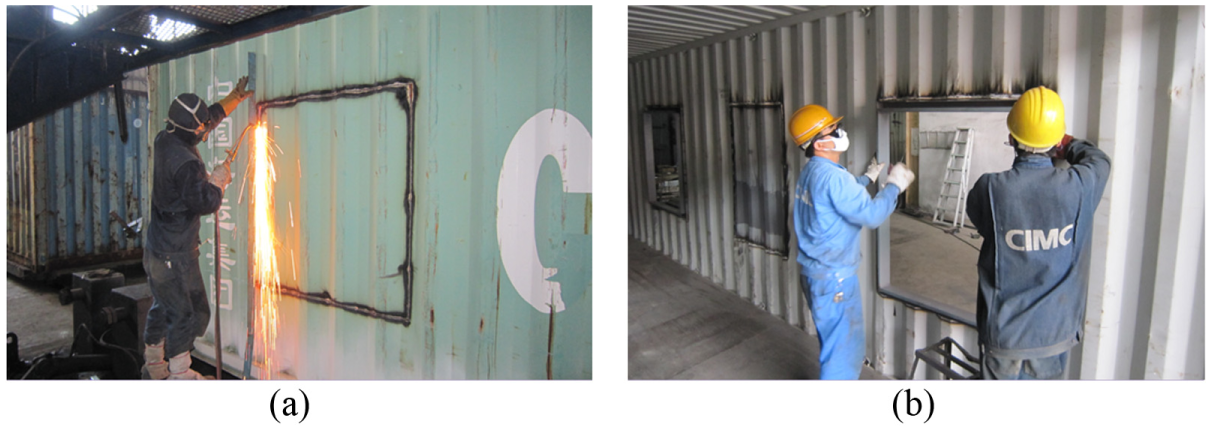
The (a) opening and (b) stiffening process of container.
Some authors21–23 had noted that when the hole area is less than 3%, the exchange of diaphragm stiffness was not large, and intact structural stiffness formula could also be used; when the hole area is more than 3%, less than 15%, and had satisfied the following conditions, the structure stiffness should consider the impact of hole area: (1) reinforcement member had been set up around hole, (2) hole spacing in the direction of vertical to the corrugated direction need at least equal to the length of the hole, and (3) hole length in the direction of parallel to the corrugated direction need not exceed the 25% of the sheeting length. So, the hole area of container structure had a great impact on container stiffness.
This article presents a study on the stiffness of container with holes with the considerations of the interactions between corrugated sheet and surroundings members. An analytical solution based on Davies and Bryan 21 and Lawson 24 and finite element simulation is also used to predict the stiffness. Finally, the theoretical analysis and finite element simulation are verified through full-scale tests of container with holes.
Theoretical analysis
In “Theoretical and experimental studies on in-plane stiffness of integrated container structure,” the corrugated sheet and surrounding members were continuously connected. However, in the condition of corrugated sheet with holes, the part boundary of corrugated sheet is free, and according to the deformation of each plate as shown in Figure 3.

The deformation of each plates.
In Figure 3,
According to Davies and Bryan 21 and Lawson, 24 the deformation can be expressed as

The “Theoretical and experimental studies on in-plane stiffness of integrated container structure” states that the corresponding corrugated sheet stiffness can be expressed as

where

where
Flexible band and stiffness band
According to Lawson, 24 the corrugated sheet of a container side wall with an open hole or a stiffening member increased around the hole can be classified into two parts: flexible band and stiffness band. The flexible band refers to corrugated sheeting that has at least one hole and makes the left and right side of the hole as boundary. The remaining part is the stiffness band. The flexible and stiffness bands are illustrated in Figure 4.

The flexible bands and stiffness bands.
In Figure 4,
Stiffness of window form
W area is intercepted from the container side wall as shown in Figure 4. The displacement

The W area deformation and partition.
In Figure 5,
Equation (4) can be obtained according to the mechanical balance of the W area

where
Thus, equation (5) can be obtained

where

Thus, equation (7) can be obtained

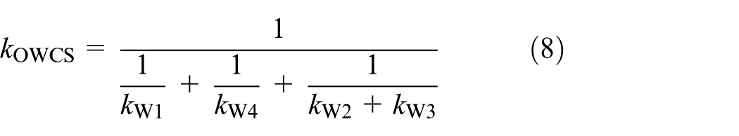
The stiffness of the W area can then be expressed as equation (8)
Stiffness of door form
The D area adopts same processing method of W area as mentioned above and as shown in Figure 6.

The D area deformation and partition.
In Figure 6,
Equation (9) can be obtained according to the mechanical balance of the D area

where
Thus, equation (10) can be obtained

where

Equation (12) can then be obtained

The stiffness of the D area can be expressed as equation (13)

Stiffness of combined window form
The C area adopts same processing method of W area as mentioned above and as shown in Figure 7.

The C area deformation and partition.
In Figure 7,
Equation (14) can be obtained according to the mechanical balance of the C area

where
Equation (15) can then be obtained

where
Let the first formula minus the second formula of equation (15), and let the first formula minus the third formula of equation (15). The third and fourth formulae of equation (16) can be obtained

Equation (17) can be obtained

The stiffness of the C area can then be expressed as equation (18)

Stiffness of corrugated sheeting with hole
The container side wall often has a number of doors, windows, and other holes to meet the requirements of architectural design as shown in Figure 4. Thus, the stiffness of the corrugated sheeting with holes can be superimposed through the preceding analysis.
The deformation of the container side wall is coordinated under external loading; thus, the displacement of the container can be expressed as equation (19)

where
Thus, equation (20) can be obtained according to equation (19)

Given that the distribution coefficient of

Equation (22) can then be obtained according to equation (20)

Stiffness of container with holes
According to Davies and Bryan 21 and ECCS 95, 22 the structure of stressed skin diaphragm is mainly bared shear loading, and bending loading is relatively small. So, in this article, the shear loading is mainly considered. In the study of non-opening container structure, that is integrated container structure, the local deformation is obvious since the containers are located on top of each other, and the axial stiffness of top side beam is limited by the corrugated sheet which cannot transfer the loading.
However, in the experiment of opening container structure, the local deformation is not obvious, and the opening container structure has a Z-shaped deformation wholly since the limited effect of the corrugated sheet to the axial stiffness of top side beam is reduced as the area of hole increased. The container stiffness mainly shares by the frame and corrugated sheeting. Equation (23) can be obtained according to Figure 8

where

The stiffness of container with holes.
In equation (23),

In equation (23),

where
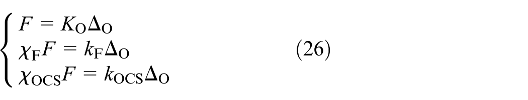
Equation (26) can be obtained through equation (23)
Equation (27) can be obtained

The unilateral stiffness of the container with holes can then be expressed as equation (28)

The stiffness of the container with holes is in accordance with the container size in ISO 668:2013 26 and is shown in Table 10.
Finite element simulation
Container model establishment
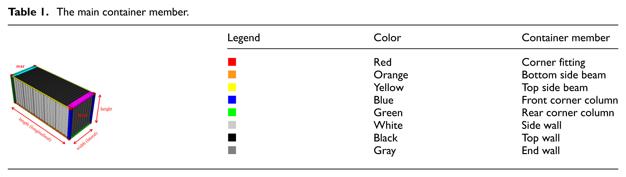
The container finite element analysis adopts nonlinear finite element software of Abaqus.27,28 The member and size of container are shown in Tables 1 and 2, and more extensive information of container can refer to relevant ISO 668:2013. 26
The main container member.
The main container size (mm).

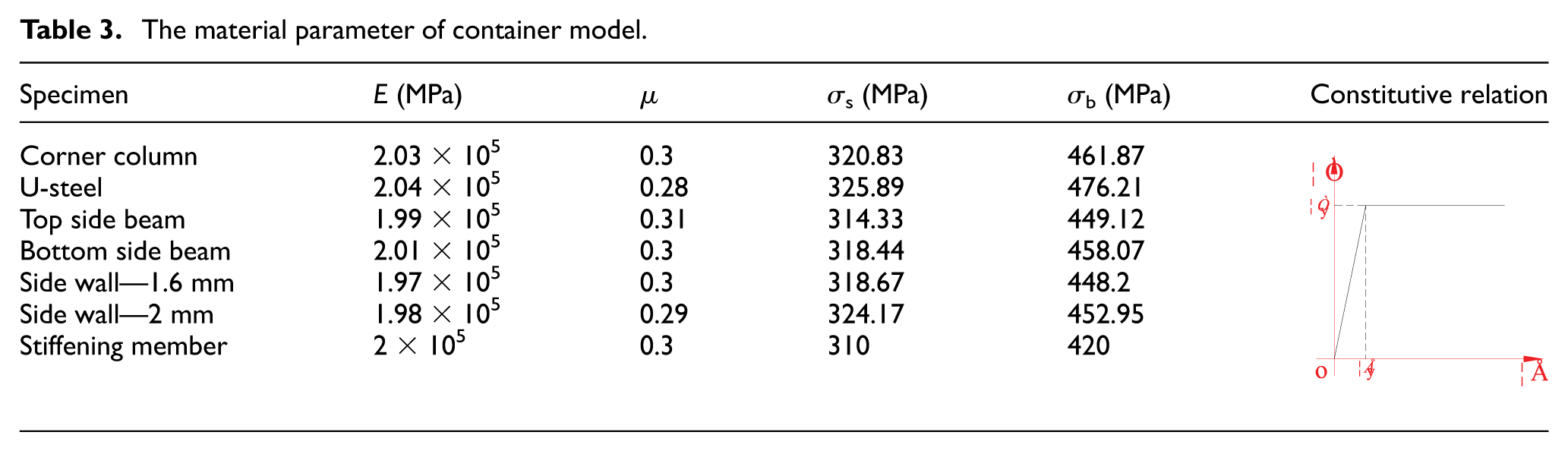
The material parameter of the container model is based on the material experiment as shown in Table 3. The density of container steel is 7.85 × 10⁻⁹ t/mm3.
The material parameter of container model.
In mesh parametric analysis, the mesh size of the top side beam, bottom side beam, front corner column, rear corner column, top end beam, and bottom end beam are 15 mm, and the mesh size of corner fitting, side wall, top wall, and end wall is 10 mm. Given that the majority of the container member is made from steel plate, the container model uses a three-dimensional (3D) shell unit. However, the corner fitting uses a 3D solid unit. Tie and coupling constraints are applied to various components of the container.
The container corner fitting uses “hex” as the element shape, “structured” as the technique of mesh controls, “C3D8R” as the element type, the node is 8, and the number of elements is 27,648. The container roof uses “tri” as element shape, “free” as the technique of mesh controls, “S3” as the element type, the node is 3, and the number of elements is 272,600. Other members of the container use “quad” as the element shape, “structured” as the technique of mesh controls, “S4R” as the element type, the node is 4, and the number of elements is 598,035.
No rigid connection is found between the container door and the entire structure, and the container door does not work on longitudinal stiffness with complexity of modeling. Thus, no consideration is given in its finite element modeling.12,13
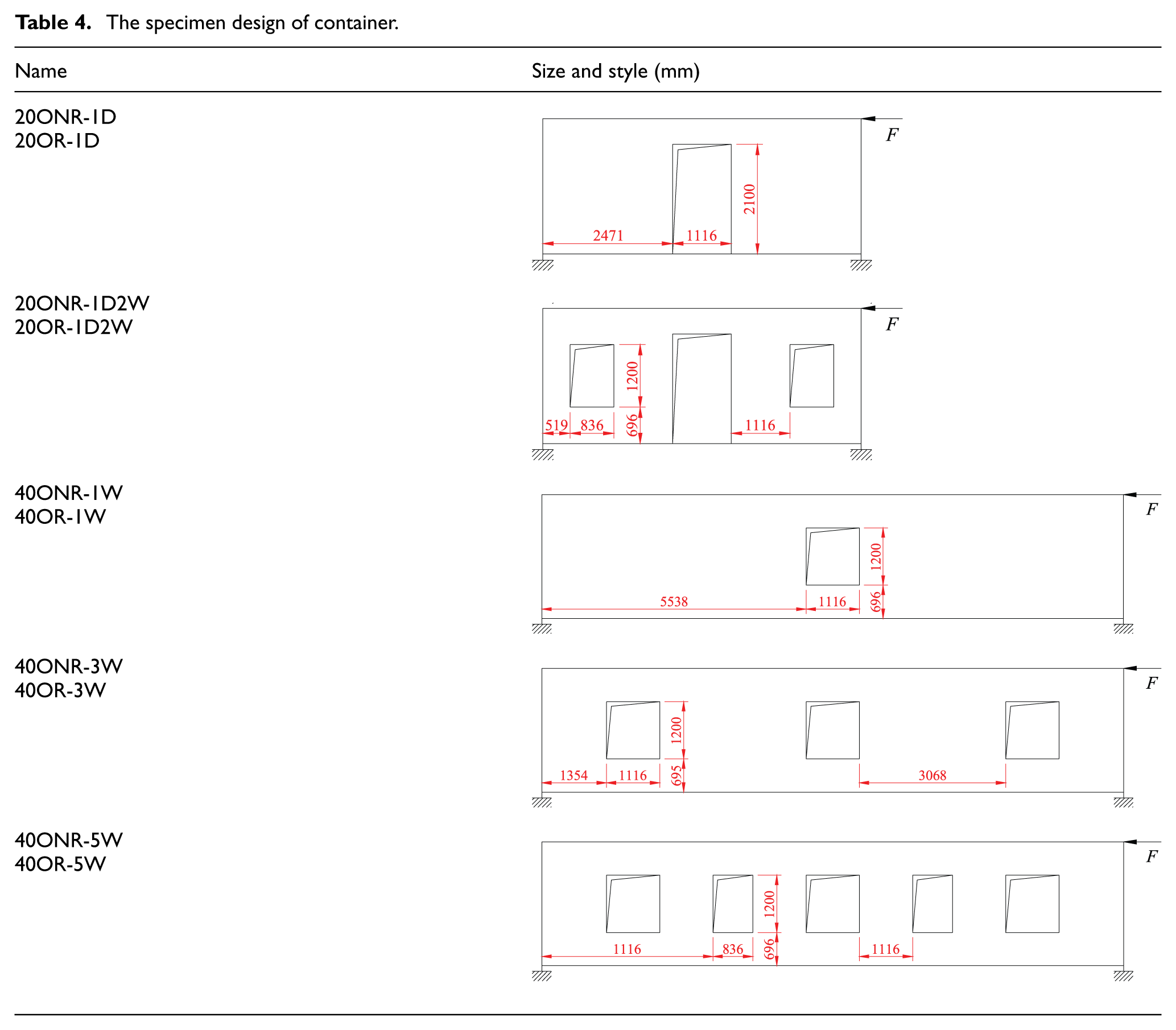
The size and style of the hole of each specimen are shown in Table 4.
The specimen design of container.
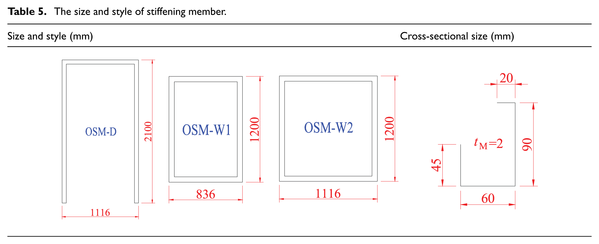
The size and style of the stiffening member are shown in Table 5.
The size and style of stiffening member.


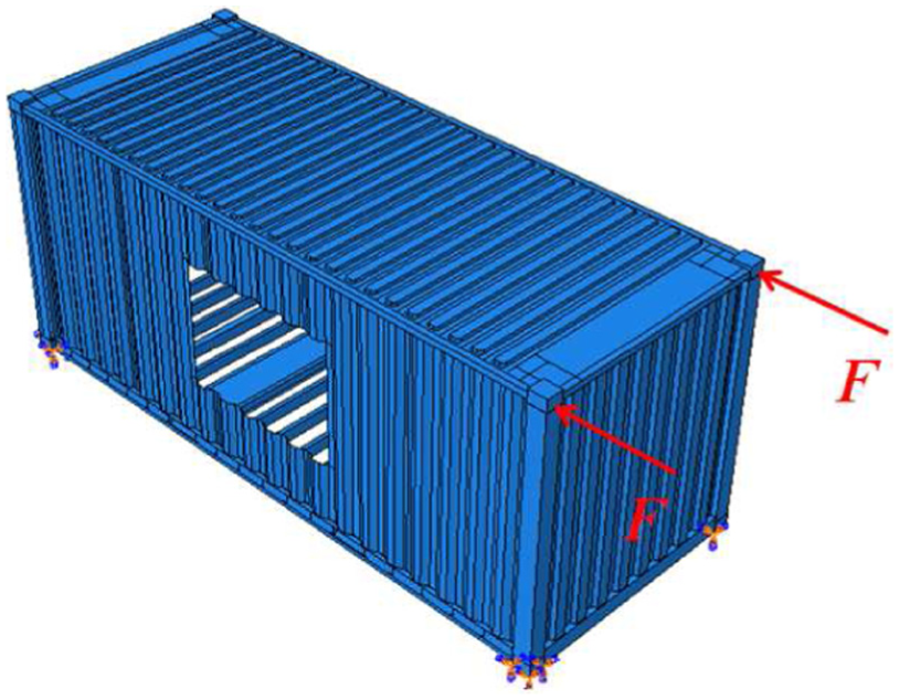
The container model is shown in Figure 9.

The container model with holes: (a) 20-ft container and (b) 40-ft container.
The loading condition is symmetrical longitudinal concentrated load, which is applied to two front top corner fittings of the container as shown in Figure 8. The research focuses on the mechanical property of the elastic stage of container; each item is loaded until one component of the container begins to yield. The constraint condition is fully constrained and is applied to four bottom corner fittings as shown in Figure 10.
The constraint and load condition of container with holes.
The following form of container is simulated as shown in Table 6. The corresponding size of the hole and stiffening member are shown in Tables 4 and 5.
The finite element model of container.

Result of finite element simulation
The finite element simulation shows the unilateral stiffness of the container with holes in the elastic range, including the group of open and non-reinforced (NR-F) and the group of open and reinforced (R-F) as shown in Table 6. The comparison of finite element simulation (NR-F) and theoretical analysis (NR-T) shows a good agreement as shown in Figure 11.

The comparison of unilateral container stiffness: (a) 20ONR-1D/20OR-1D, (b) 20ONR-1D2W/20OR-1D2W, (c) 40ONR-1W/40OR-1W, (d) 40ONR-3W/40OR-3W, and (e) 40ONR-5W/40OR-5W.
Experimental verification
The container steel is special weathering steel—CORTEN STEEL—whose performance is different from general building structural steel. In order to fully understand its performance, container material experiment is carried out as shown in Figure 12 and relevant testing data as shown in Table 3. The experimental method is in accordance with ISO 6892-1:2009 29 Metallic materials—Tensile testing—Part 1: Method of test at room temperature and ISO 377:1997 30 Steel and Steel Products—Location and Preparation of Samples and Test Pieces for Mechanical Testing.

The tensile experiment: (a) the tensile specimen size (mm) and (b) the experimental phenomenon.
Experimental preparation
Experimental equipment and arrangement
The experiment is studied in Test-bed lab of China International Marine Containers (Group) Ltd. (CIMC). The experimental equipment mainly includes reaction frame, as shown in Figure 13, DH3816 static strain measurement system, force sensor (range, 0–22 t; sensitivity coefficient, 0.03% FS), dial gauge (range, 0–50 mm; sensitivity coefficient, 0.01 mm), and electric resistance strain gauge (sensitivity coefficient, 2.06–2.12). The container with holes is used in the experiment as shown in Figure 14.
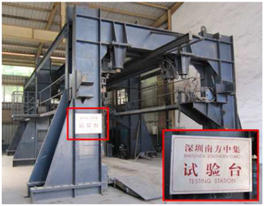
The reaction frame.

The container with holes.
The experimental equipment and container arrangement are as shown in Figure 15.

The experimental equipment and container arrangement.
Loading program
The research of the experimental items of 20ONR-1D, 20ONR-1D2W, 40ONR-1W, 40ONR-3W, 40ONR-5W, 20OR-1D, 40OR-1W, and 40OR-3W mainly focuses on the mechanical property of the elastic stage. The research of the experimental items of 40OR-5W and 20OR-1D2W mainly focuses on the mechanical property of the elastic–plastic stage.
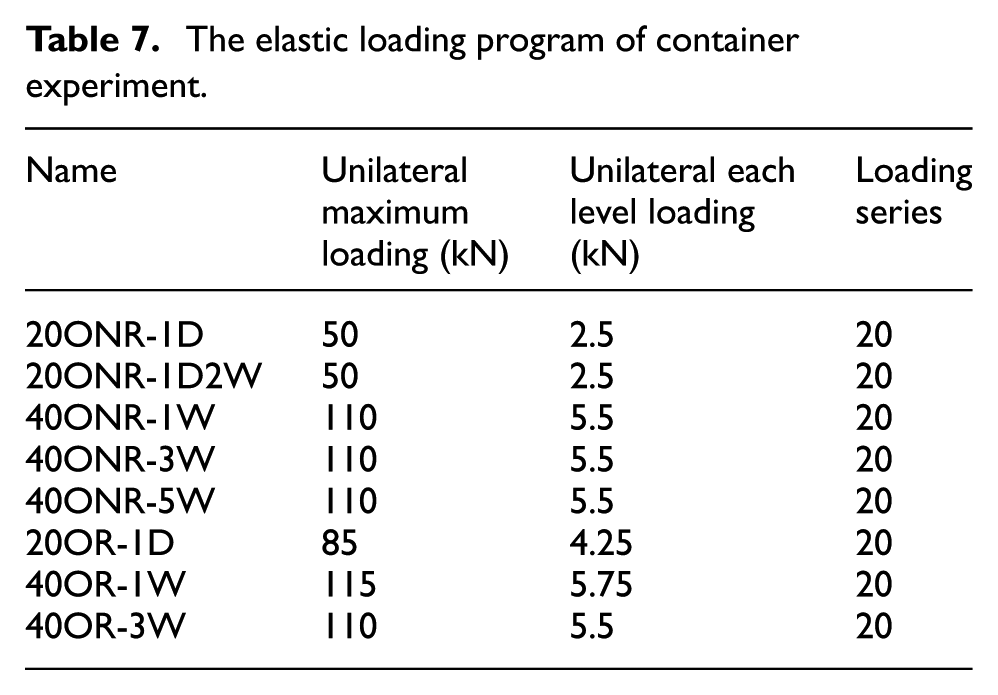
According to finite element simulation and material tests, the loading program uses a loading control method for experimental items of 20ONR-1D, 20ONR-1D2W, 40ONR-1W, 40ONR-3W, 40ONR-5W, 20OR-1D, 40OR-1W, and 40OR-3W as shown in Table 7, and the loading program uses a loading control method in the elastic phase and displacement control method in the plastic phase for experimental items of 20OR-1D2W and 40OR-5W as shown in Table 8.
The elastic loading program of container experiment.
The elastic–plastic loading program of container experiment.

Experimental result
The experiments of 20ONR-1D, 20ONR-1D2W, 40ONR-1W, 40ONR-3W, 40ONR-5W, 20OR-1D, 20OR-1D2W, 40OR-1W, 40OR-3W, and 40OR-5W are as shown in Figure 16.

The experimental item of container stiffness: (a) 20ONR-1D, (b) 20ONR-1D2W, (c) 40ONR-1W, (d) 40ONR-3W, (e) 40ONR-5W, (f) 20OR-1D, (g) 20OR-1D2W, (h) 40OR-1W, (i) 40OR-3W, and (j) 40OR-5W.
Each unilateral load–displacement curve is relatively symmetrical and synchronous, which indicates that every experimental item is in the elastic stage and has no large torsion as shown in Figure 17.
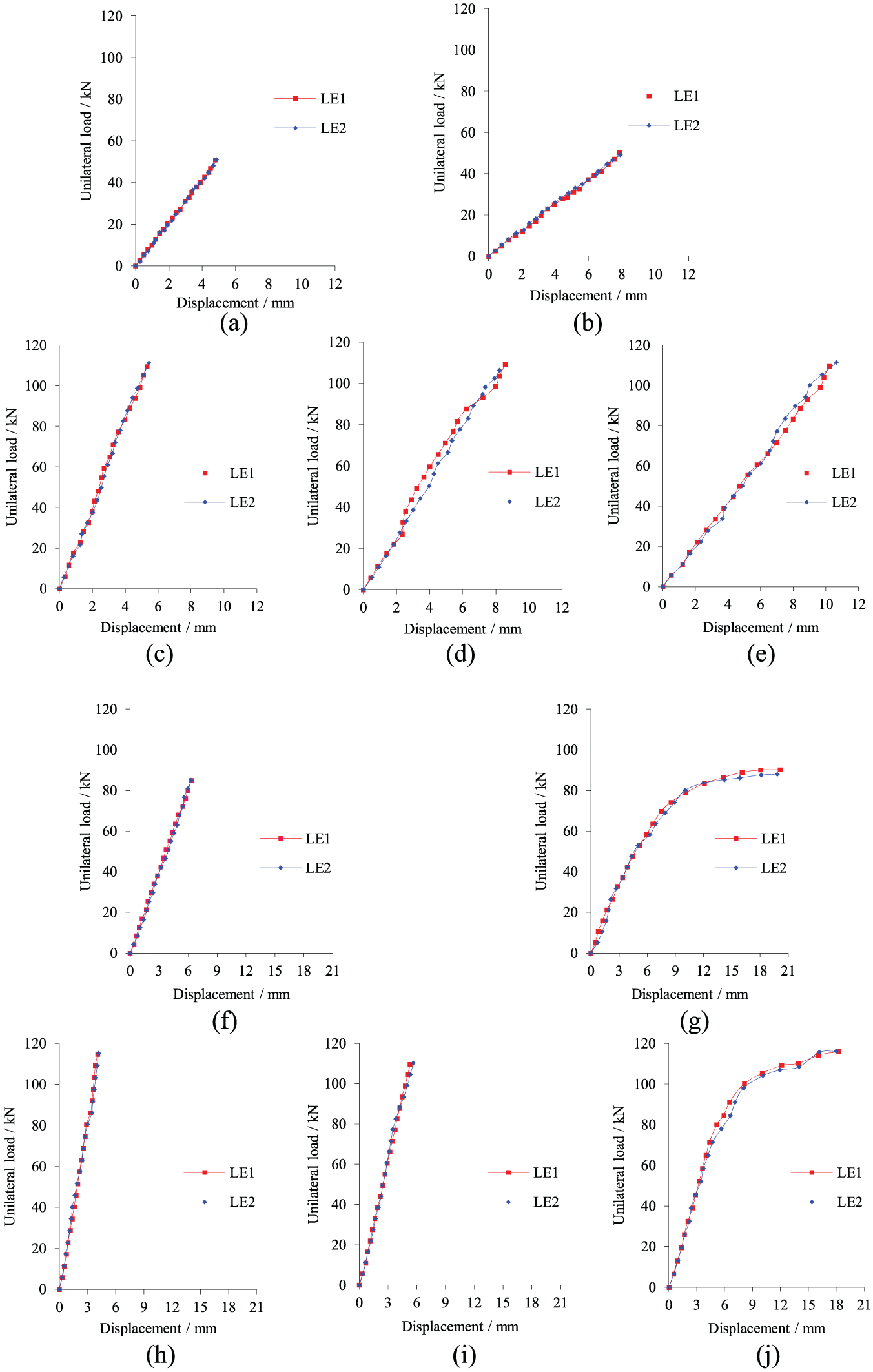
The unilateral load–displacement curve of each experimental item: (a) 20ONR-1D, (b) 20ONR-1D2W, (c) 40ONR-1W, (d) 40ONR-3W, (e) 40ONR-5W, (f) 20OR-1D, (g) 20OR-1D2W, (h) 40OR-1W, (i) 40OR-3W, and (j) 40OR-5W.
The unilateral container stiffness of each item is as shown in Table 9.
The unilateral container stiffness of each experimental item (kN/mm).

LE: the loading end.
The same type of container (20 or 40 ft) is used in the same process (stiffening or non-stiffening). The container stiffness decreases as the hole size increases. The 40-ft container which adopts the uniform changing of the hole area shows a rapid decrease in the container stiffness as the hole area increases. The corrugated sheet has a significant effect on container stiffness as shown in Figure 18.

The container stiffness comparison of 40-ft containers with holes: (a) the open and non-reinforced group of 40-ft container and (b) the open and reinforced group of 40-ft container.
Given the stiffening member, the stiffness value of the reinforced container with holes is significantly greater than that of the non-reinforced container with holes as shown in Figure 19. With the increase in hole area, the stiffening member can significantly improve the container stiffness, for example, 20OR-1D improves 29.09%, 20OR-1D2W improves 78.17%, 40OR-1W improves 30.14%, and 40OR-3W improves 54.43%. However, when the hole area increased to a certain extent, the stiffening member cannot significantly improve the container stiffness, for example, 40OR-5W improves only 47.56%.

The container stiffness comparison of stiffening and non-stiffening containers: (a) the open group of 20-ft container and (b) the open group of 40-ft container.
The damage of the container structure is accompanied by the fracture of stiffening member when the loading of 40OR-5W reaches 229.87 kN and the loading of 20OR-1D2W reaches 178.29 kN. For 40OR-5W, damage initially occurs at the top of the hole, which is near the loading end as shown in Figure 20. For 20OR-1D2W, damage initially occurs at the top of the hole, which is in the middle as shown in Figure 21.

The 40OR-5W damage phenomenon.

The 20OR-1D2W damage phenomenon.
40OR-5W and 20OR-1D2W gradually reach yielding with increased loading. The bearing capacity of 40OR-5W and 20OR-1D2W is approximately 209.43 and 167.2 kN, respectively.
Theoretical analysis (T) and finite element simulation (F) have a good agreement with experiment (E), which can be verified as shown in Table 10.
The verification of container stiffness (kN/mm).

E: experiment; F: finite element simulation; T: theoretical; LE: the loading end; FE: the error between finite element simulation and experiment; TE: the error between theoretical analysis and experiment.
Conclusion
Based on the preceding analysis, the following conclusions are obtained:
The stiffness of the container with holes was derived by the stiffness distribution between the frame and the corrugated sheet based on the stiffness of the corrugated sheet with the holes of window, door, and combined window.
The container stiffness decreased with the increase in the hole area. The stiffening member improved the container stiffness significantly when the hole area increased. The stiffening member did not improve the container stiffness significantly when the hole area increased to a certain extent.
The load–displacement curve and container stiffness of each experimental item are obtained. The bearing capacity, damage phenomena, and location of 20OR-1D2W and 40OR-5W are determined.
Footnotes
Academic Editor: Jose Ramon Serrano
Declaration of conflicting interests
The author(s) declared no potential conflicts of interest with respect to the research, authorship, and/or publication of this article.
Funding
The author(s) received no financial support for the research, authorship, and/or publication of this article.