
Abstract
This article presents analytical, numerical, and experimental studies on the in-plane stiffness of container buildings. First, based on diaphragm theory, parallel corrugated direction stiffness of corrugated sheet has been deduced, and based on energy method, shear modulus of two elastic principal directions of orthotropic plate has been deduced, and through stiffness conversion method, the stiffness relationship between parallel corrugated direction and vertical corrugated direction has been obtained. Combined with container frame, the container stiffness of loading end and non-loading end, as bottom side beam fixed, has been obtained. Second, through the software Abaqus, full-scale container model has been established. The loading–displacement curve of finite element model has been compared with theoretical analysis and has a good agreement. Third, through 20 and 40 ft container, corresponding experimental verification has been done, and by comparison of container stiffness, the theoretical analysis and finite element simulation have been verified. Finally, based on verified finite element model, parametric analysis of corrugated sheet size, corrugated sheeting cross section, elasticity modulus of top side beam, and every plate action for container stiffness have been given. Research result has made feasible in design and construction of container buildings and can provide some references to corresponding specification preparation.
Keywords
Introduction
As a light steel structure, containers have increasingly been used for building structures as shown in Figure 1. Container buildings have many advantages and applications. First, container steel is recyclable, thus reduces energy consumption and environmental pollution. Second, containers are normally manufactured in factory, transported to and quickly assembled at construction sites, which follows a standardized design and construction process that is easy to manage and construct. Third, containers can be in a variety of forms depending on architectural design requirements. Due to the above advantages, containers have been used not only for general residential buildings but also for public buildings, disaster relief housing, field and military constructions. 2

The container building. 1
Although, as a special form of buildings, containers have been widely accepted by the construction industry, there are still demands from the design community for further study on their structural performance. In this aspect, Suzuki and colleagues3–5 used finite element method to analyze vibration of stacked containers. The numerical model was validated by full-size tests. However, the majority of research has focused on dynamics of container stacking in maritime transport. Børvik and colleagues6,7 used aluminum board to design envelope structures, and then used finite element method to simulate mechanical properties of the protective structures under impact of explosion. Finally, a full-size container with protective structure was tested to verify the finite element analysis. In these studies, the interactions between the side walls and the frame of container and the integrated container stiffness were not considered. In accordance with the ISO requirements, Sinha and Prakash 8 proposed a space frame model for calculating stresses and deflections of containers subjected to some loading conditions when compared with experimental results. It was found that the sidewall simulations provided unsatisfactory results, probably because modeling a container as a space frame for lifting and restraint tests had not represented a good simulation of the actual test conditions. Giriunas and colleagues9,10 developed finite element models to predict stiffness of a variety of container structures under various loading conditions. Zha and Zuo11,12 proposed a container optimal model, taking the lightest total weight as the objective function, and the strength and stiffness as the constraint conditions. The optimal cross-sectional size of beam and column was obtained. Zuo and Zha 13 used diaphragm theory to give a mechanical analysis and stiffness calculation method of container with holes and then used Abaqus to give the influence law of parameters on the stiffness of container with holes. Finally, five experimental studies of container with holes were verified. Zha and colleagues14–16 proposed the formula of container stiffness as the single layer and multi-span, multi-layer and single-span, and multi-layer and multi-span based on the principle of displacement coordination and diaphragm theory. Then proposed a new isolation system based on friction energy between containers, and the relationship between equivalent damping ratio and friction coefficient of sliding isolation structure had been obtained.
It can be seen from the above that the majority of research on container buildings were on architectural design for maritime transport, rather than considering containers as building structures. The general code of steel structure17,18 had often considered a corrugated sheet as building envelope structure without considering its own mechanical property and its interaction with the surrounding frame structure and had no provision of appropriate design and calculation methods. The literature19–21 introduced that the connection between corrugated sheet and surrounding members was joined by bolt, and this boundary condition was discontinuous. However, the boundary condition of container structure was different, which was joined by welding continuously between corrugated sheet and surrounding members. So, the literature19–21 failed to reflect the real boundary condition of container structure.
Therefore, for a better and economic design, further research is required to take into account the mechanical property of corrugated sheet, as well as its interaction with container frame.
This article presents a study on the in-plane stiffness of container structures with the considerations of the interactions between corrugated sheet and surroundings members. An analytical solution based on diaphragm theory is proposed. Finite element method is also used to predict the stiffness. Finally, the theoretical analysis and finite element simulations are verified through full-scale test of container structures.
Theoretical analysis
Deformation of corrugated sheets
Assuming that a corrugated sheet is subjected to an in-plane shear,

The corrugated sheet of container side wall. EBCDEB is a wave band of the corrugated sheet.
In Figure 2, h is the height of the container side wall and
When the sheet is subjected to the in-plane loading,22,23 a representation part of section is shown in Figure 2(c), lines TT, SS, and BB in the mid-width of the top, side, and bottom plates will be twisted to their respective new positions T′T′, S′S′, and B′B′. The deformations are due to a combined action of bending and shearing as shown in Figure 3.
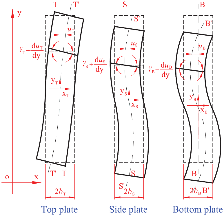
The deformation of each plate of corrugated sheet.
In Figure 3,
Bending deformation
The deformations of the top, side, and bottom plates due to bending are shown in Figure 4. In Figure 4,
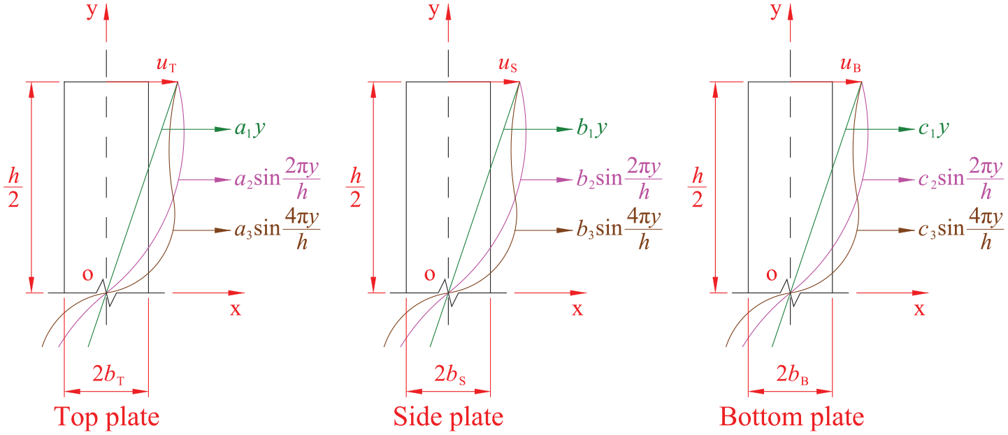
The bending deformation of each plate of corrugated sheet.
In Lawson,
23
it was shown that sufficient accuracy can be achieved by choosing the first two terms, where for simplicity, only
Equation (1) is the in-plane displacement of the sheet due to bending

where
Shear deformation
The in-plane displacement of the top, side, and bottom plates of corrugated sheet due to shearing can be expressed in a similar form as

where
Thus, the in-plane shear strains,

where
Axial deformation
The axial deformation of the top, side, and bottom plates of the corrugated sheet can be expressed as 23

where
Introducing equations (1) and (3) into equation (4) yields

where
Considering deformation compatibility of the top, side, and bottom plates, all the three plates have the same axial deformation, that is

where
Energy of corrugated sheets
There are two types of bending in the plates, that is, the one causing defection in the plan of the plates and the one causing deflection transverse to the plan of the plates. Therefore, the associated bending energies are calculated separately.
Bending energy due to out-of-plane deformations
Considering the deformation of a wave of the corrugated sheet, this part of energy can be calculated from the deformation shown in Figure 5.

The deformation of portal frame of corrugated sheet.
In Figure 5,
Since the deformation of a wave of the corrugated sheet appears anti-symmetric, analysis was carried out by Lawson for only half of the wave and the bending moments, and

where D is the bending stiffness of the sheet; and

Inserting equation (8) into equation (7) gives

where
Since the bending moments across the width of the plate are constant and can be calculated from the moments at the intersections, the bending energy due to out-of-plane bending can be computed as

where s is the coordinate along the cross-sectional length of a wave band.
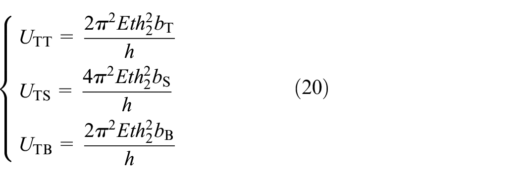
Introducing equation (9) into equation (10), the bending energy is obtained as follows

where
Bending energy due to in-plane deformations
The bending within the plane of plates can be formulated as

where
Thus, the bending energy of the top, side, and bottom plates of corrugated sheet can be expressed as

where
Considering equations (1), (12), and (13), the bending energy of the top, side, and bottom plates of corrugated sheet is calculated as
where t is the cross-sectional thickness of the top, side, and bottom plates.
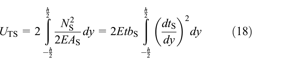
Shear energy due to in-plane deformations
Shear strain energy density of the top, side, and bottom plates of corrugated sheet can be expressed as

where
Thus, the respective shear energies are

where
Introducing equation (3) into equation (16), the shear energies of the top, side, and bottom plates are obtained as

where G is the shear modulus of container steel.
Tension energy due to in-plane deformations
The tension energy of the side plate can be expressed as
where
Since the top and bottom plates have the same axial deformation as the side plate does, tension energy of the top and bottom plates can be written as

where
Inserting equation (5) into equations (18) and (19) yields the tension energies of the top, side, and bottom plates
Deformation compatibility of corrugated sheets
The literature
18
derived the following formulas for calculating

where
Longitudinal in-plane stiffness of corrugated sheets
The total energy of a wave of corrugated sheet can be expressed as
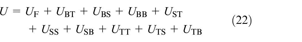
where U is the total energy of a wave band.
Introducing equations (11), (14), (17), and (20) into equation (22), the total energy is

It can be seen from equation (23), the total energy of a wave of corrugated sheet is a function of 14 unknown coefficients, that is,

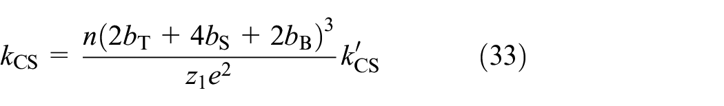
where coefficients before the unknown parameters can be found in Appendix 1.
Equation (24) can be solved by letting
From Zha, 24 the stiffness of the n-wave plates shown in Figure 6 can be calculated by
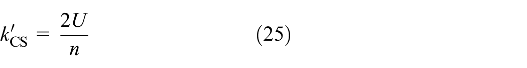
where n is the number of wave band of corrugated sheet and
The deformation of corrugated sheet with n wave bands.
Stiffness conversion of corrugated sheets
Equation (25) provides a solution for calculating in-plane shear stiffness of the n-wave corrugated sheet in the flute direction. In order to find the in-plane shear stiffness in the transverse direction, the conversion process proposed by the literature19,25 is adopted in the following calculation.
The shear modulus of corrugated sheet relative to the x- and y-directions
The deformation of a corrugated sheet can be treated as the deformation of an orthotropic plate as proposed in the literature19,25 and shown in Figure 7.

The deformation of corrugated sheet: (a) parallel to corrugated direction and (b) vertical to corrugated direction.
In Figure 7,
From the literature19,25 and Figure 7, the shear modulus relative to the y-direction and x-direction can be expressed as

where
Stiffness conversion
From Figure 7, the following stiffness can be calculated

where
Considering that the shear strain of Figure 7 can be expressed as


Hence, from equations (30) and (31)
Introducing equations (26) and (27) into equation (32) yields
or

where e is the horizontal projection length of a wave band of corrugated sheet;
In-plane shear stiffness of container side wall
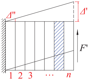
Under the external loading as shown in Figure 8, the wall of container should deform coordinately. The axial stiffness of top side beam is rarely and only part of F can be transmit to the non-loading end (NLE). In this case, it can be assumed that axial force of the top side beam is distributed trapezoidal, and the maximum axial force
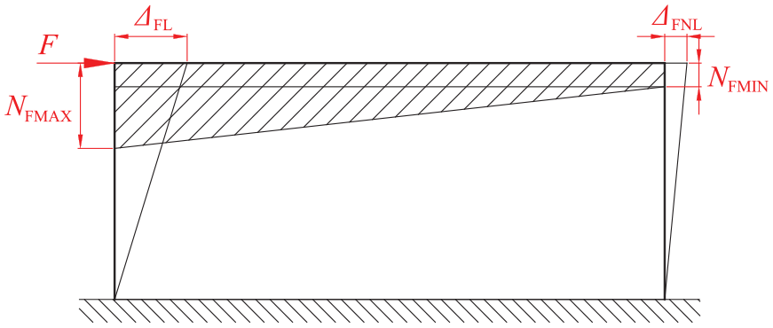
The axial force of top side beam.
In Figure 8,
The internal force in the top beam consist two components, that is, an axial force
where

Consequently,

where

From equations (36) and (37), we have

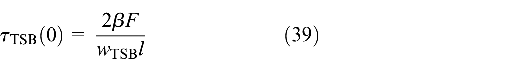
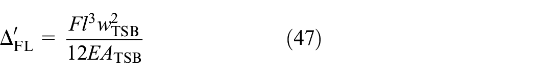
As shown in Figure 9(b), container stiffness is mainly born by top side beam. As shown in Figure 10, and based on the equilibrium condition of top side beam, the following can be obtained as shown in equation (39).

The decomposition of axial force of top side beam. (a) Part of the axial force of rectangular distribution αF acting on the corner column and corrugated sheeting and (b) Part of the axial force of triangular distribution βF acting on the top side beam.

The triangular distribution of axial force of top side beam.
In Figure 10,
where
As shown in Figure 10, the shear of any cross section can be expressed as

And then, the axial deformation of top side beam can be expressed as

where
As shown in Figure 10, the energy of top side beam can be expressed as

where
From Castigliano’s theorem, the relationship between
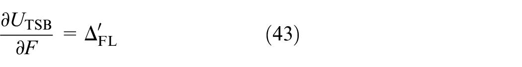
And then, the


Substituting equations (44) and (45) into equations (38) and (41), we obtain

As shown in Figure 9, superimposed Figure 9(a) and (b), the displacement of LE and NLE of container can be expressed as

And then, the container stiffness of LE and NLE can be expressed as follows. The container component size can be referred to the literature 26
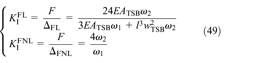
where

According to the container size in the literature, 26 the unilateral container stiffness of LE and NLE of 20 and 40 ft, respectively, can be obtained as shown in Table 1.
The unilateral container stiffness of theoretical value (kN/mm).

LE: loading end; NLE: non-loading end.
Finite element simulation
Container model establishment
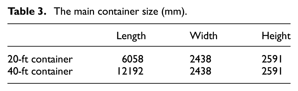
Nonlinear finite element software Abaqus13,14,27 is used as primary means of finite element analysis. The member and size of container are shown in Tables 2 and 3, and more extensive information of container can be referred to the relevant literature. 26
The main container members.

The main container size (mm).
Material parameter and constitutive relationship of container model are based on the material experiment as shown in Table 4 and Figure 11. The density of container steel is 7.85 × 10⁻⁹ t/mm3.
The material parameters of container model.


The constitutive relationship of container model.
Element size, element shape, technique of mesh control, and element type of container model are shown in Tables 5 and 6.
The elements of container model.
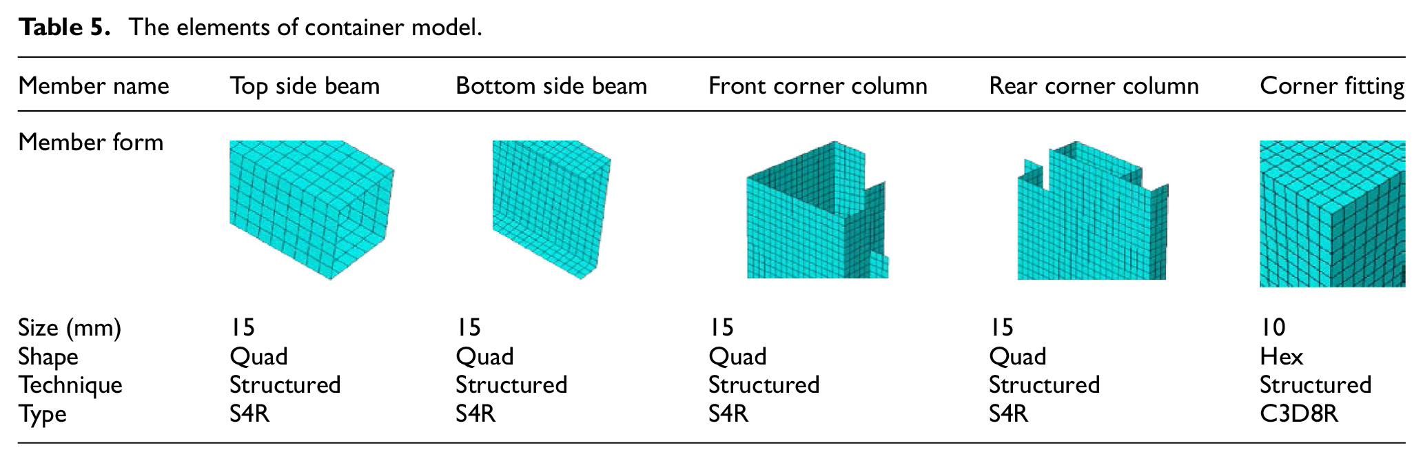
The elements of container model.

Through the above analysis, the container model is as shown in Figure 12, and the finite element model has a good agreement with the real container as shown in Figure 12.
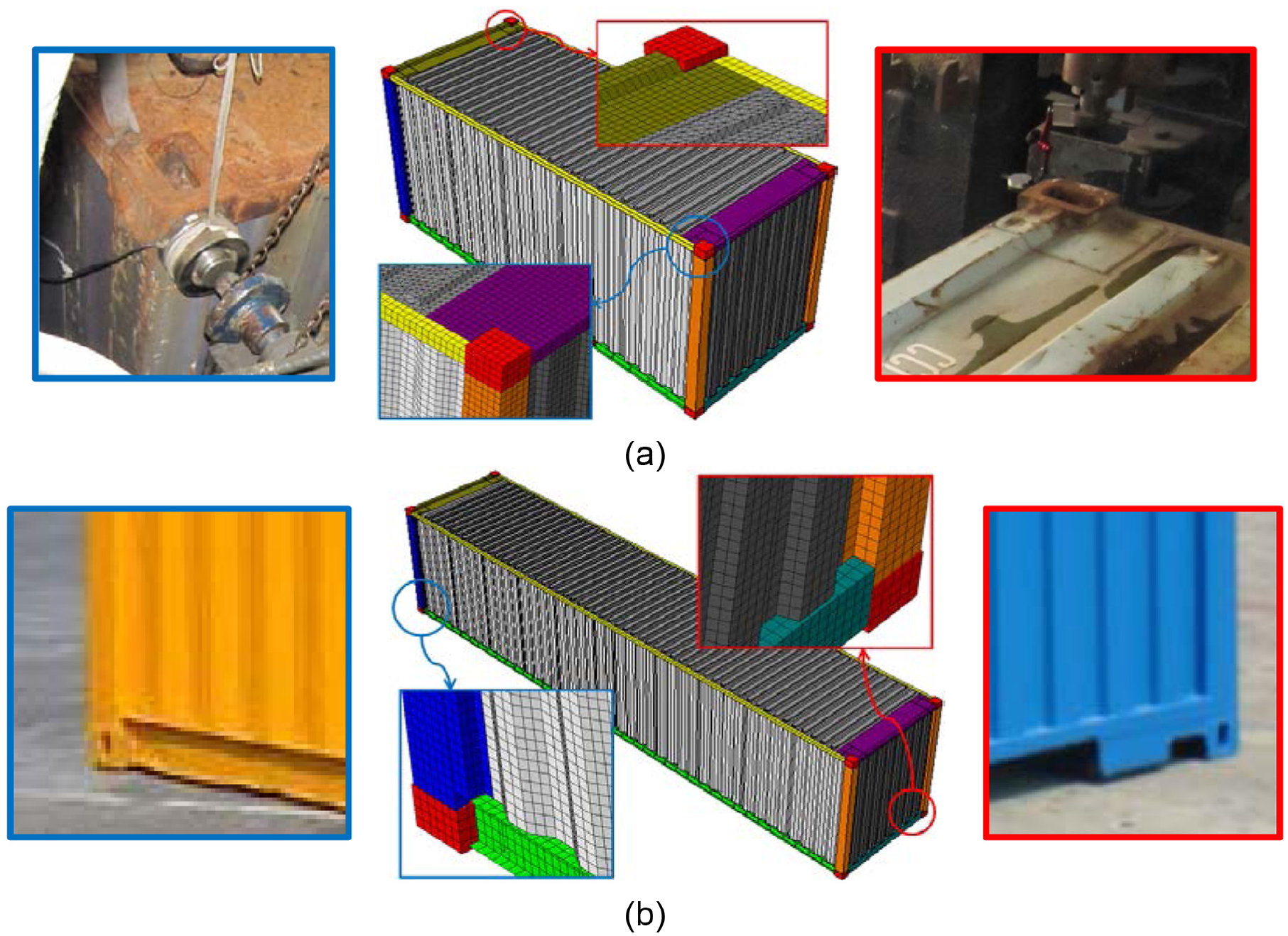
The container model: (a) the 20-ft container model and (b) the 40-ft container model.
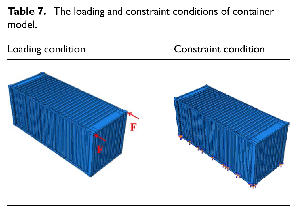
Longitudinal concentrated loading is symmetrically applied to two front top corner fittings of container. The major research is on the mechanical property of elastic stage of container; each item is loaded until one component on container began to yield. The constraint condition mainly uses corner fitting and bottom side beam fixed as shown in Table 7.
The loading and constraint conditions of container model.


Result of finite element simulation
Through finite element simulation, the Mises stress of each component on container is in elastic range as shown in Figure 13, and the unilateral container stiffness of each item is shown in Figure 14. Through comparison, the container stiffness of LE and NLE of finite element simulation (F) and theoretical analysis (T) have a good agreement as shown in Figure 14.

The Mises stress contour of container model: (a) the 20-ft container model and (b) the 40-ft container model.

The comparison of unilateral container stiffness (T and F): (a) 20-ft LE, (b) 20-ft NLE, (c) 40-ft LE, and (d) 40-ft NLE.
Experimental verification
Taking into account, the container steel is special weathering steel (Corten Steel), the performance of which is different from general building structural steel. So, in order to fully understand its performance, container material experiment is carried out as shown in Figure 15 and relevant experimental data are shown in Table 4. Experimental method is in accordance with the relevant literature. 28

Tensile experiment: (a) the tensile specimen size (mm) and (b) the experimental phenomenon.
Experimental preparation
Experimental equipment and arrangement
Experimental equipment mainly includes the reaction frame, as shown in Figure 16(a); the DH3816 static strain measurement system, as shown in Figure 16(b); force sensor (range 0–22 t, sensitivity coefficient 0.03%FS); dial gauge (range 0–50 mm, sensitivity coefficient 0.01 mm); and electric resistance strain gauge (sensitivity coefficient 2.06–2.12). Containers are standard 20 and 40-ft container, as shown in Figure 16(c) and (d).

Experimental equipment: (a) the reaction frame, (b) the DH3816 static strain measurement system, (c) the 20-ft container, and (d) the 40-ft container.
The arrangement of experimental equipment and container is shown in Figure 17.
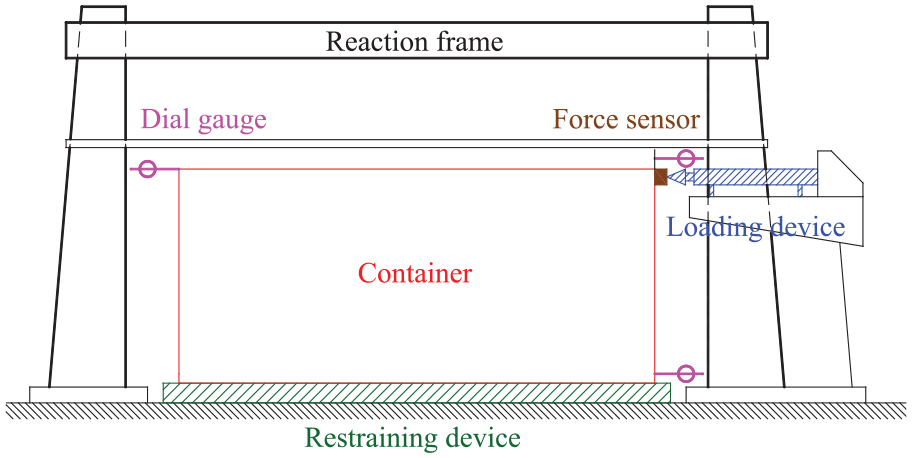
The arrangement of experimental equipment and container.
Loading program
The constraint and loading are similar with finite element simulation. According to finite element simulation and material tests, the loading program adopts loading control method. The corresponding loading program is shown in Table 8.
The loading program of container experiment (kN).

Experimental result
The experiment of 20 and 40 ft is shown in Figure 18.

The container experiment: (a) the 20-ft container and (b) the 40-ft container.
From unilateral loading–displacement curve of LE and NLE, each unilateral loading–displacement curve is relatively symmetrical and synchronous and indicates that every experimental item is in the elastic stage and no large torsion, as shown in Figure 19.

The unilateral loading–displacement curve of each experimental item: (a) 20-ft LE, (b) 20-ft NLE, (c) 40-ft LE, and (d) 40-ft NLE.
As can be seen from experiment, container stiffness of each experiment is shown in Table 9.
The unilateral container stiffness of each experimental item (kN/mm).
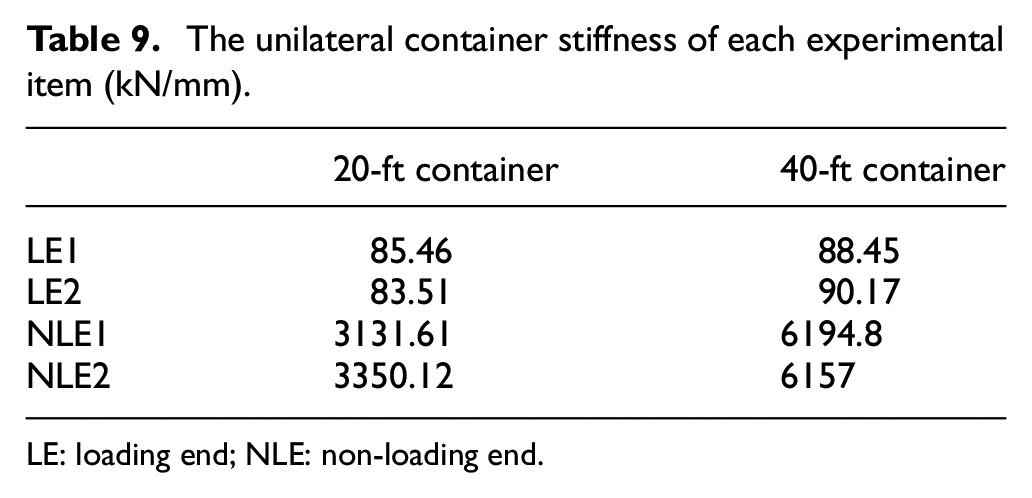
LE: loading end; NLE: non-loading end.
As the bottom side beam is being fixed, the container side wall is constraint, the corrugated sheet at LE bulges outward slightly, and with the container length increasing, the bulge deformation only occurs in the LE of corrugated sheet. So, the LE stiffness of 20-ft container is slightly lesser than 40-ft container. As the bottom side beam is being fixed, the increase in the container length has no significant effect on container stiffness.
Through comparison, theoretical analysis (T) and finite element simulation (F) have a good agreement with experiment (E) and can be verified from the above conclusion, as shown in Tables 10 and 11.
The verification of 20-ft container stiffness (kN/mm).

LE: loading end; NLE: non-loading end.
The verification of 40-ft container stiffness (kN/mm).
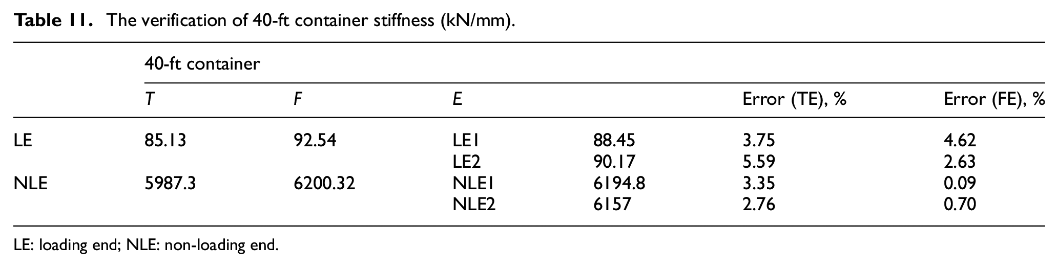
LE: loading end; NLE: non-loading end.
Parametric analysis and corresponding proposals
Parametric analysis of finite element model
In order to fully understand the mechanical property of the container and its member, the parametric analysis of finite element model is analyzed.
Size of corrugated sheet
The influence law of container stiffness by the corrugated sheet size is shown in Figure 20. As can be seen from the figure, the container stiffness reduces gradually as the corrugated sheet height increases, and the container stiffness initially increases gradually then unchanged basically as the number of wave band of corrugated sheet n increases.

The influence law of container stiffness (corrugated sheet size).
Section of corrugated sheet
The cross section of corrugated sheet is shown in Figure 21.

The cross section of corrugated sheet.
The influence law of container stiffness by t and E is shown in Figure 22. As can be seen from the figure, the container stiffness increases gradually as the t increases, and the container stiffness increases gradually as the E increases.

The influence law of container stiffness (t and E).
The influence law of container stiffness by e and d is shown in Figure 23. As can be seen from the figure, the container stiffness increases gradually as the e increases, and the container stiffness reduces gradually as the d increases.
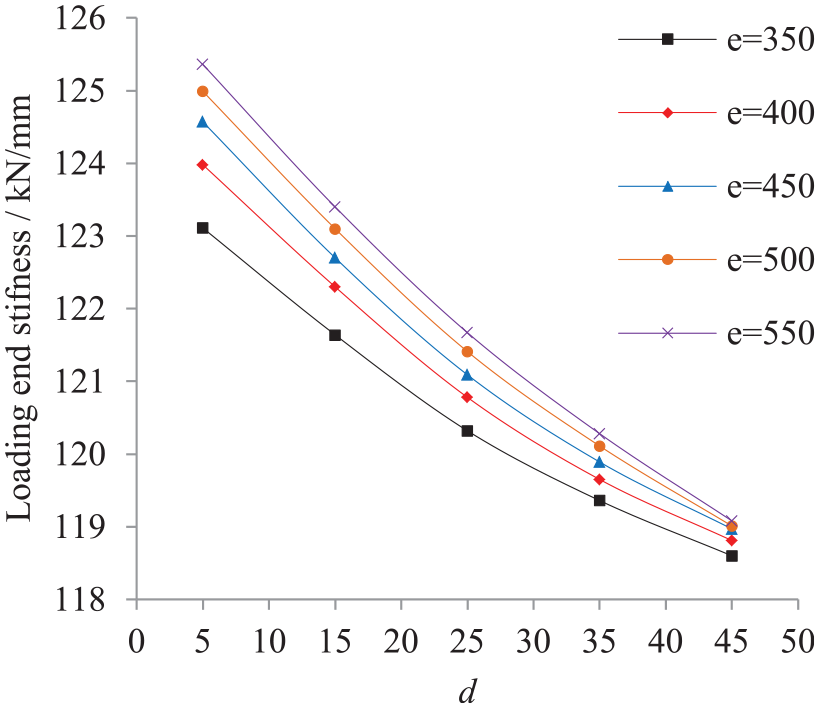
The influence law of container stiffness (e and d).
The influence law of container stiffness by

The influence law of container stiffness (
Elasticity modulus of top side beams
The influence law of container stiffness by the elasticity modulus of top side beams is shown in Figure 25. As can be seen from the figure, the container stiffness increases gradually as the elasticity modulus of top side beams increases. As elasticity modulus of top side beams increases, 40-ft container stiffness increases greater than 20-ft container.

The influence law of container stiffness (the elasticity modulus of the top side beams).
Side wall, front wall, and roof
The influence law of container stiffness by side wall, front wall, and roof is shown in Figure 26. As can be seen from the figure, the front wall has no effect on container stiffness basically, and the side wall has a great effect on container stiffness, and the roof has a small effect on container stiffness. FW, SW, and R represent the side wall, front wall, and roof, respectively; the 20-ft SW represents the 20-ft container with the side wall removed; and the other symbols have the same meaning, as shown in Figure 26.

The influence law of container stiffness (the side wall, front wall, and roof).
Conclusion
Based on diaphragm theory, the stiffness of corrugated sheet which is parallel to corrugated direction had been deduced. Based on energy method, the shear modulus of two elastic principal directions of orthotropic plate had been deduced. Based on stiffness conversion method, the stiffness of corrugated sheet which is vertical to corrugated direction had been deduced.
Based on the stiffness of corrugated sheet and decomposition of axial force of top side beam, the container stiffness formula of LE and NLE as bottom side beam fixed had been deduced.
Through 20 and 40-ft container experiment, theoretical analysis and finite element simulation had been verified, and the loading–displacement curve of each item had been obtained.
Based on verified finite element model, the influence law of container stiffness—such as corrugated sheet size and cross section—elasticity modulus of top side beam, and every plate action had been given.
Footnotes
Appendix 1
Academic Editor: Jianqiao Ye
Declaration of conflicting interests
The author(s) declared no potential conflicts of interest with respect to the research, authorship, and/or publication of this article.
Funding
The author(s) received no financial support for the research, authorship, and/or publication of this article.