
Abstract
In this study, a self-charged power bank integrated with an energy harvester was developed to harness human biomechanical energy and sustainably recharge a power bank. In the energy harvester, a spring–mass damping system is used to transform the human body’s movement during walking into the rotation of a gear train and drive rotary generators to produce electricity to recharge the battery through a rectifying circuit. A mathematical model was built to examine the power output of the energy harvester under different excitation conditions. A prototype was built to test the performances of the harvester, and experiments on the prototype fixed on the ankle, wrist, and torso were conducted, which indicated that the measured power output was 0.35 W, 0.16 W, and 10 mW, respectively, when testers walked at 2.0 m/s (the circular frequency of foot step is about 14.5 rad/s). The experiments indicate that a higher walking velocity as well as excitation amplitude and frequency could result in higher output power.
Introduction
As the popularity of portable electronics increases, mobile power banks are necessary to ensure that devices remain available when working outdoors for long periods of time; for example, a cell phone used on a trip could be recharged from a mobile power bank. Although a power bank can extend the electricity capacity of the devices to a certain degree, it still has a limited amount of electricity; thus, it needs to be recharged frequently. However, it is occasionally unfeasible to recharge the exhausted power bank on a trip or in fieldwork. Therefore, it is necessary to find alternative methods to solve the power supply problem of mobile devices. Several novel methods have been investigated to sustainably recharge a battery. A few of these methods focus on recharging the battery using solar energy, such as Brogan et al. 1 and Wang and Yen, 2 who acquired an output power of 550 mW and 56 µW using a solar cell, respectively. Although solar cells are capable of being easily embedded in cloth, a large-sized solar cell is required to harness considerable energy and is available only under the condition of sufficient light, which hinders the widespread use of the solar cell. It is known that significant kinetic energy dissipates in the form of heat during human motion, which implies that the human body can be a tremendous source of energy. A total of 900 calories can be extracted when just 1 g of fat is consumed. 3 Thus, even if a small fraction of this energy could be utilized, the human body would become an enormous and sustainable energy source. In fact, a few methods extracting energy from human motion or body heat have already been proposed. Kim et al. 4 reported that a maximum of 224 nW of power could be obtained using a thermoelectric element, while Maisam et al. 5 used a thermoelectric converter to harvest 20 µW of electricity power. In addition to harnessing energy from body heat, a few researchers have investigated harvesting impact energy from a foot strike6–9 using micro-generators or piezoelectric materials in the shoe sole. When a human walks, the trail of the torso (or mass point of body) relative to the ground appears approximately as a sine wave instead of a straight line. 10 This motion pattern of the torso provides a possibility of converting considerable kinetic energy of the human body to electrical power. A few energy-harvesting devices based on a backpack have been developed to harvest the kinetic energy of the torso motion. For example, Rome et al. 11 used a suspended-load backpack to convert human vertical movement and generated 7.4 W of electric power. Xie and Cai12,13 developed a suspended backpack harvester to harness the mechanical energy of the human body, which increased the energy-harvesting efficiency by 40%.
The above-mentioned harvesting devices for human kinetic energy were designed for a special type of human motion or a designated human body joint; therefore, they cannot be utilized for daily use. Using a mobile power bank as an oscillating mass, a new energy-harvesting device was proposed to harness human kinetic energy and sustainably recharge the power bank. This energy-harvesting device consists of a battery in a power bank, which serves as the oscillating mass, spring components, gear train to speed up the motion, generator for mechanical–electrical energy conversion, and circuit interface to regulate the electricity from the generator. The battery and spring components constitute the mass–spring oscillating mechanism, which is used to harness human motion. During human walking, the oscillating mechanism is driven by an external vibration, and the “captured” motion is transferred to the gear train to increase the frequency and rotate the generator. The electricity produced by the generator later recharges the battery after the rectifier and the regulator. The proposed energy-harvesting device with a mobile power bank can be used for daily use, which could spontaneously work anywhere if carried on any part of the human body, including the torso and the upper and lower limbs.
This report is organized as follows: section “Patterns of human motion” introduces the pattern of human motion, section “Energy harvester” describes the design of the harvester as well as provides the mathematical model and analysis of the harvester, section “Prototype design and experiments” introduces the prototype design and the experiments to validate the theoretical analysis, and section “Conclusion” draws the conclusions from this study.
Patterns of human motion
When a human walks normally, the motion pattern appears to be periodic. However, the trunk, upper limbs, and lower limbs do not share a unique motion pattern. Thus, the motion patterns of the different parts will be demonstrated.
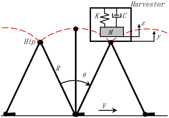
The typical human motion in normal walking is highly complex. Figure 1 provides the human motion and posture during a normal walking cycle. The motion of the body’s center of mass (COM), which is nearly at the same position as the hip, is the basis of the human movement.11,14 In bipedal human locomotion, the trunk displacement is achieved by lower limb movements that primarily result in the forward displacement of the COM. As indicated by the dashed line in Figure 1, the body’s COM moves forward and downward simultaneously with each step, and it subsequently moves upward when the body weight is transferred from one leg to the other. 15 Therefore, during a normal walking cycle, the human trunk moves up and down relative to the mean forward velocity, and it also displays speed fluctuations in the direction of progression. Additionally, the motion of the human trunk can be characterized by a sinusoidal function, in which the amplitude and frequency are dependent on both the walking velocity and the human body dimensions. As depicted in Figure 2, the walking model can be approximated as an inverted pendulum, and the hip displacement in the vertical direction during walking, which is of interest for energy harvesting, can be expressed as a sinusoidal function of the walking frequency ω with an amplitude Y as follows 16


Pattern of human motion and posture in a typical walking cycle.
Schematic diagram of torso motion pattern during normal human walking.
As a result of the periodical movement in human torsion in the vertical direction, the energy harvester can be placed on the human trunk to harvest this reciprocating motion. Figure 2 depicts the schematic diagram of the human trunk motion and the energy harvester on the torso. Based on Figure 2, the maximum amplitude of the vertical displacement during walking is

Additionally, the circular frequency value for walking can be empirically approximated as a function of the walking velocity and the leg length as follows 18

Based on the above equations, the vertical displacement of the torso can be simply approximated as a function of the walking velocity and the leg length. Statistical data 19 have demonstrated that the leg length accounts for 53% of a person’s stature. Assuming that the walking velocity is approximately 4–7 km/h, or approximately 1–2 m/s, during normal walking, the walking frequency and the vertical magnitude can be obtained with respect to the walking velocity. Figure 3 illustrates the frequency and the magnitude of vibration in the human trunk with respect to the walking velocity. This figure indicates that the relationship between the walking velocity and the frequency is nearly linear, which is similar to the relationship between the walking velocity and the magnitude.

Circular frequency and vertical magnitude of normal walking in terms of walking velocity.
The motion of the upper limbs, which is characterized as an out-of-phase swing, is considerably simpler than that of the trunk. When the right leg and torso move forward, the left arm moves forward and vice versa for the opposing leg and arm. The upper limbs can be modeled as a single simple pendulum that has its mass concentrated at its COM. Assuming that the angle


(a) Harvester mounted on the human hand and lower limbs, (b) schematic model of the upper limbs during normal walking, and (c) schematic model of the lower limbs during normal walking.
The maximum amplitude swinging angle is A, and the upper limb shares the same walking frequency ω with the torso. However, different positions of the arm result in different displacements along the circular arc, which accounts for the different excitation magnitudes of the oscillating system. Thus, both sides of equation (4a) are multiplied by L1, which represents the distance between a certain position where the harvester is mounted and the axle of the shoulder joint, and equation (4a) can then be rewritten as follows

where
During normal walking, gait cycles are repeated, including the swing phase and the stance phase for each foot. The right foot’s initial contact with the ground occurs while the left foot is still on the ground, that is, there is a period of double support between the initial contact on the right foot and the toe of the left foot leaving the ground (toe-off). During the swing phase of the left foot, only the right foot remains on the ground, providing a period of right leg singular support that ends with the initial ground contact by the left foot. Then, there is another period of double support until toe-off occurs on the right foot. The left leg singular support period corresponds to the right swing phase. The cycle ends with the next initial ground contact by the right foot. Although the lower limb motion pattern is complex, it could still be seen as a single simple pendulum swinging as a sinusoidal curve, as shown in Figure 4(c). Similarly, the angular displacement relative to the mean forward velocity can be expressed as follows

where B is the maximum amplitude swinging angle. The lower limb has the same walking frequency ω as the other two parts. Similar to the upper limbs, the distance between the installation position of the harvester and the hip joint should also be considered. Therefore, equation (5) can be rewritten as follows

where
As discussed above, despite the different motion patterns, the trails of the torso, upper limbs, and lower limbs could be expressed as a similar simplified equation (equations (1), (4), and (5)). For the sake of convenience, a general expression for these three motion patterns can be given as follows

where
Energy harvester
Working principle
The energy harvester, which is designed to embed into a typical power bank, is schematically depicted in Figure 5. The power bank consists of a dynamic system, including chargeable battery, springs, micro-generator, planetary gear train, and circuit, and a static structure, which includes a gear rack and a container shell. The battery and springs constitute an oscillating system, which can be excited by the external vibration of the human body, and there is a relative linear motion between the battery and the container shell. Because the gear rack is attached to the container shell, the linear motion of the battery is transformed into rotation of the gear train. The gear train accelerates the rotation and drives the generator to produce electricity. Because the human motion is irregular, the generated voltage from the generator is also irregular; therefore, rectifier and regulator circuit of the harvester is necessary to regulate the electricity and store it in the battery.

Schematic diagram of the energy harvester.
In this energy harvester, as many components as possible are designed to be the oscillating mass so that the maximum amount of kinetic energy can be absorbed by the oscillating system. The battery, gear train, generator, and circuit are assembled in the container, which can oscillate together with the springs. To keep the oscillation stable, there is a track groove to fit with the guiding rail attached on the shell; furthermore, the guiding rail is made of polytetrafluoroethylene (PTFE) to reduce friction during oscillation.
Dynamic model
When the energy harvester works on the human body, the oscillating system can be considered approximately to be a single-degree-of-freedom (SDOF) oscillating system, where the damping mass is M, and the total stiffness coefficient of the springs is K. Then, the governing equation can be expressed as follows

where y is the function of the external excitation and C is the total damping coefficient of the oscillating system, which consists of the mechanical damping coefficient

If the oscillating system is excited by the sinusoidal excitation, the dynamic response of the system will also be a sinusoidal function with the same frequency according to the vibration theory. Therefore, the response function can be expressed as follows

By inserting the response function into equation (8), the response amplitude and phase can be given as follows

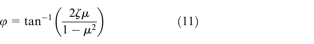
where
In order to capture as much human motion as possible, the resonant frequency of the spring–mass oscillating system in the harvester should be matched with human walking frequency. When a person walks in different velocities, the circular frequency is variable, as shown in Figure 3. Assume that the average circular frequency of human normal walking is
The micro-generator typically achieves a reasonable efficiency when it gains high speed. However, the excited velocity of the external motion is extremely low; therefore, an acceleration gear train is necessary to speed up the low-speed human motion. Figure 6 illustrates the schematic diagram of the transmission in the harvester. The linear motion is first transformed into rotation by the rack gear, and the pinion gear Z0 then transmits the rotation to its coaxial gear train. The rotator of the generator is then accelerated by the gear train. The pinion gear has the same module m as the rack gear. The total gear ratio of the planetary gear train is


Schematic diagram of the transmission in the harvester.
Power output of the energy harvester
The total transient power transferred from the human motion to the oscillating system is a product of the electrical damping force

Thus, based on the transient power, the average power can be calculated as follows

where

Average input power versus walking frequency and amplitude, where
Circuit interface of the energy harvester
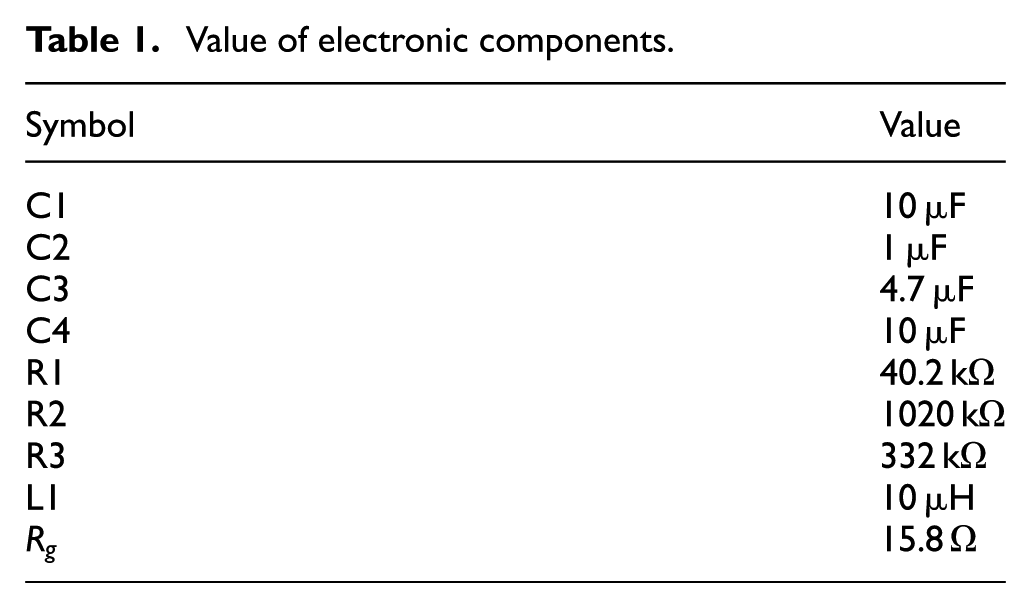
The electricity produced by the generator will be used to recharge the battery after the rectifier and the regulator. Considering the input power range is extremely large, a commercial DC/DC converter LTC 3105, which has a wide input voltage range (0.25–5 V), is applied to the recharging circuit. As depicted in Figure 8, the circuit interface consists of the rectifier, regulator, and battery. The electronic parameters are provided in Table 1. The irregular output electricity from the generator is first rectified by the bridge rectifier and then becomes a stable direct current after the regulator. The output voltage is 4.1 V, which is suitable for charging the Li-ion battery.
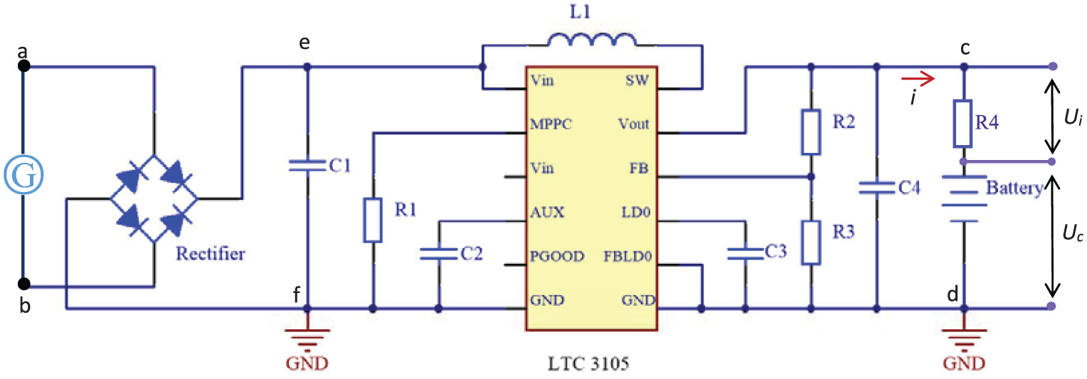
Rectifier and regulator circuit of the harvester.
Value of electronic components.
Prototype design and experiments
A prototype and an experimental setup were built to validate the theoretical analysis mentioned above. As indicated in Figure 9, the prototype harvester had a total weight of 126 g, among which the moving damping mass weighed 87 g. The overall dimensions of the prototype harvester are 98 mm in length, 70 mm in width, and 20 mm in height. The container and the outer shell were made of ABS plastics. A mini DC motor (MITSUMI, M15N series) is used as a generator to produce electricity. The harvester prototype was fixed to a belt, which made the harvester convenient to mount on the torso, arms, and feet of the human body. For the convenience of observing the output power of the harvester, the cover of the prototype was removed. A treadmill, capable of tuning the moving velocity, was used in the experiments to accurately measure the walking velocity. In the harvester prototype, the total spring stiffness was set to be approximately 40 N/m so that it could match the total oscillating mass and work properly. The mechanical damping coefficient was estimated by experiments. First, set to the open circuit, the container of the energy harvester (i.e. the oscillator) was pulled by a displacement and then released, and the oscillating displacement curve was recorded. Finally, the free decay curve of the damped oscillation curve was fitted to obtain damping ratio in MATLAB using the method in Venuti and Bruno. 20 The mechanical damping ratio of the prototype was estimated to be approximately 0.108. The two-level gear train, which is used to accelerate the rotation, has a gear ratio of 26. The rated efficiency of the micro-generator used in the prototype was 0.51, and the efficiency of the interface circuit was measured to be approximately 82%.

Experimental setup and harvester prototype: (a) prototype mounted on the upper limb, (b) prototype mounted on the lower limb, (c) prototype mounted on the torso, and (d) front view of the prototype.
To measure the transient charging current, a small resistance R4, which was set to 1 Ω so that the minimal voltage dropped, was connected in series with the battery, as indicated in Figure 9. By measuring the voltage drop Ui of the small resistance using an oscilloscope, the charging current could be calculated as

Waveforms of the voltages and the current: (a) waveforms of the output voltage from the micro-generator, (b) instant power output from the generator, and (c) voltage after rectifier between points e and f.

Waveforms of the voltages and the current: (a) waveforms of the charging voltage to the battery after the rectifier and the regulator circuit interface, (b) waveforms of the charging current to the battery recorded by indirectly measuring the voltage on resistance R4, and (c) waveforms of power to the battery by multiplying the rectified voltage and the charging current.
The experiments performed on the treadmill were conducted to measure the power output with respect to the changing walking velocities. Figure 12 provides the experimental results of the power output for the energy harvester for walking velocities between 1.4 and 2.0 m/s when fixed at different positions, where the simulated data are used as a reference. Each walking velocity tuned by the treadmill was repeated 10 times, and the average and standard error were then calculated. Different walking velocities could result in different walking frequencies and magnitudes for an individual participant; therefore, the power output from the energy harvester changed accordingly. This figure indicates that the experimental data were close to the simulated data, and they followed the same trend, indicating that the theoretical study was correct; however, there were a few differences between the experimental and the simulated data. When the prototype harvester was fixed on the ankle, the measured average electrical power to charge the battery was approximately 0.35 W at a velocity of 2.0 m/s, as indicated in Figure 12(a). Similarly, in the case of the harvester fixed on the wrist and on the torso, the measured power to the battery was 0.16 W and 10 mW, respectively. There is a similar pattern for the power output for different installation positions of the harvester, and due to the different amplitudes, the power output at the different installations is also discrepant. Based on Figure 12, the different walking velocities could result in different walking frequencies, thus the frequency ratio changed. Therefore, the harvester power output changed accordingly. In order to test the capacity of power supply for application modules, two typical application experiments were conducted during human daily activities. First, an iPhone was recharged from the harvester fixed on ankle. In the second example, the harvester fixed on wrist was successfully applied to power a Samsung mobile phone. In the two experiments, these application devices worked continuously and with good status.
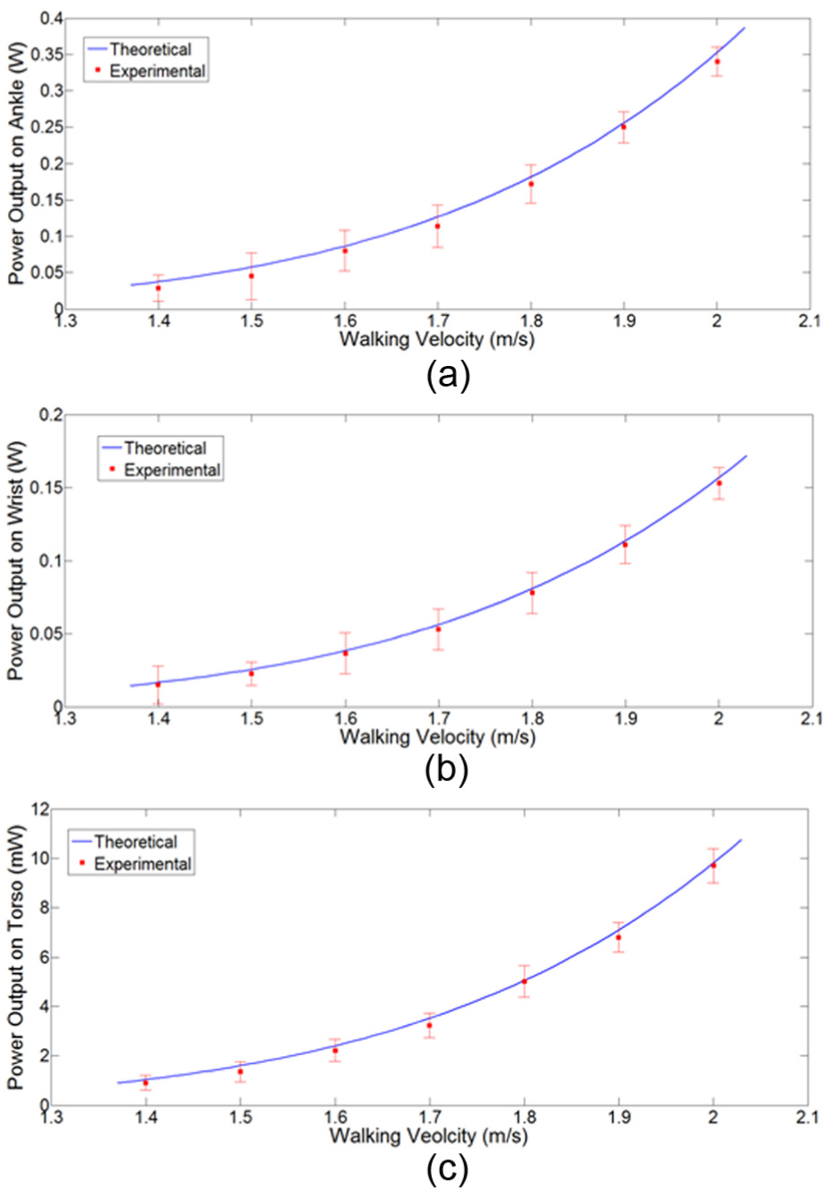
Average output power with respect to the walking velocity when the energy harvester was fixed on (a) ankle, (b) wrist, and (c) torso.
Conclusion
In this work, an energy harvester integrated with a power bank was developed to harness human biomechanical energy, convert it into electricity, and recharge the battery of the power bank. A mass–spring–damping oscillating system, where the weight of the battery acted as a damping mass, was used to capture human motion during walking, and a gear train was used to convert the linear motion into rotation and drive the micro-generator to produce electricity. A mathematical model of the energy harvester was built to analyze and optimize the power output. An energy harvester prototype was built to test the power output. Experiments on the ankle, wrist, and torso were conducted, which indicated that the measured power to charge a battery was 0.35 W, 0.16 W, and 10 mW, respectively, and the results indicated that the experimental data agreed well with the simulation. The self-charged power bank by energy harvesting could effectively improve the usability.
Footnotes
Academic Editor: ZW Zhong
Declaration of conflicting interests
The author(s) declared no potential conflicts of interest with respect to the research, authorship, and/or publication of this article.
Funding
The author(s) disclosed receipt of the following financial support for the research, authorship, and/or publication of this article: This work was supported by the National Natural Science Foundation of China (grant no. 51575188), the Fundamental Research Funds for the Central Universities (grant no. 2014ZZ0020), and the Industrial Technology Research and Development Funds of Guangdong Province (grant no. 2015A020214007).