
Abstract
In this article, the numerical simulation of a 2.0-MW wind energy converter coupling is achieved by three-dimensional computer-aided design modeling technique and finite element method. The static performances and the buckling characteristics of the diaphragm coupling are investigated. The diaphragm coupling is divided into three substructures, namely, torque input end, the middle section, and the torque output end. Considering the assembly and contact conditions, the simulation analysis for stress responses of the diaphragm coupling is carried out. The buckling factor and buckling mode of the diaphragms are obtained, and the geometric parameters of the diaphragms are optimized according to their buckling characteristics. The relationship between the pretightening force of the bolts, which tighten the friction flange and the friction plate, and the sliding torque is given by an empirical formula. The reasonable ranges of the pretightening force and tighten torque of the bolts are recommended. The fatigue analysis of the diaphragms is completed, and the results show that the diaphragms are competent to the designed life of the diaphragm coupling.
Introduction
The wind energy is one of the most pollution-free, abundant, and economical sources of renewable energies, 1 and the growing utilization of the regenerative energies has fostered a rapid expansion of wind farms.2,3 The annual installed capacity of wind turbine generator systems has grown increasingly in recent years. 4 However, the wind power equipments also face challenges in two aspects: they should be capable of running in all kinds of extreme weather and bearing complicated alternative wind pressure and need to run reliably over 20 years. These challenges put forward strict standard for the design and assembly of the key components in the wind power equipments.
In a wind turbine generator system, the diaphragm coupling plays an important role of a connecter that transmits torque through static friction and takes precaution against overload through the maximum static friction. Besides, it has other functions on occasion, for example, reducing system vibration; compensating axial, radial, and angular offsets; and linking or separating the shaft ends. Therefore, the stress analysis, buckling load calculation, and some other mechanical analysis are necessary for the design and assembly of the diaphragm coupling. There are many literature published on these subjects, such as diaphragm material design, diaphragm strength analysis, and fatigue life prediction of the diaphragm couplings. Calistrat 5 pointed out that the performance of a metal diaphragm coupling is determined, to a large extent, by its endurance limit. Sekhar and Prabhu 6 believed that the unsuitable connection between a shaft and a coupling may lead to severe vibration, and they simulated the resonant condition through finite element method (FEM). Landon and Counter 7 studied the axial vibration characteristics of metal flexing coupling. Birkholz et al. 8 proposed that diaphragm couplings can not only serve as the converter of high torque and rotational speed but also compensate the axial, radial, and angular offsets of the shaft ends. Based on the different bearing states of the diaphragm couplings, Xu and Kaiqin 9 obtained the strength and stiffness of the diaphragm couplings. However, in most of the literature, the numerical simulations were achieved with independent components. There are few researches carry on the stress and buckling analysis of the assembled structures in which the assembly relationship, the assembly stress and the contact conditions need to be considered.
This article, therefore, is devoted to present and analyze the above issues. For the diaphragm coupling of a 2.0-MW wind energy converter, components of the coupling are properly established by three-dimensional (3D) modeling technique. Assembly process is achieved based on cooperative relationships among the components. Considering the assembly relationship and contact conditions, the static stresses of the diaphragm coupling are analyzed to affirm all components satisfy the strength requirements. For its vital role in transmitting torque, the buckling factors of the diaphragms under maximum torque are calculated and the geometric parameters of the diaphragms are optimized. Finally, the relationship between the pretightening forces of the bolts, which tighten the friction flange and the friction plate, and the slip torques is investigated.
Geometry and assembly of the coupling
In a wind turbine generator system, the coupling is used to connect the gearbox high-speed shaft and the generator drive shaft. It mainly consists of the following components: flat key coupling, keyless coupling, brake flange, taper sleeve, friction flange, friction plate, two diaphragm groups, connection tray, and end cap. The main components of coupling are shown in Figure 1(a)–(l).

Main components of the diaphragm coupling: (a) connect tray, (b) brake flange, (c) friction flange, (d) end cap, (e) friction plate, (f) flat key coupling, (g) taper sleeve 1, (h) taper sleeve 2, (i) inner circle of the keyless coupling, (j) outer circle of the keyless coupling, (k) diaphragm, and (l) tachometer disk.
Components are assembled according to the cooperative relationship among them. Figure 2(a) shows a 3D view of the diaphragm coupling assembly, and Figure 2(b)–(d) shows the front view, top view, and bottom view of the diaphragm coupling.

Structure of diaphragm coupling: (a) 3D view, (b) front view, (c) top view, and (d) bottom view.
Numerical simulation model
A detailed finite element (FE) analysis is conducted on the stress responses of the diaphragm coupling bolts’ pretightening forces and maximum torque. To make the stress analysis easier, the diaphragm coupling is divided into three substructures: the torque input end, the middle section, and the torque output end, as shown in Figure 3.

Three substructures of coupling: (a) input, (b) middle, and (c) output.
At the torque input end, the flat key coupling and brake flange are assembled together through 16 bolts of M20 × 70, which make sure the input torque can be reliably transmitted to the brake flange. Then, the torque is delivered from the brake flange to the diaphragm group of input end by two hexagon head bolts. By the other two hexagon head bolts, with which the diaphragm group and the taper sleeve 1 are fitted together, torque is passed on to the taper sleeve 1 of the middle section.
At the middle section, the taper sleeve 1 transmits torque to the fiber tube and then to the taper sleeve 2. In addition, the taper sleeve 2, the friction plate, the friction flange, and the end cap are associated together by 10 bolts of M16 × 100. Therefore, torque is delivered to the friction flange in the form of static friction with the friction plate and then to the diaphragm group in the torque output end.
At the torque output end, the diaphragm group transfers torque to the connection tray. Then, the torque is delivered to the keyless coupling through 28 hexagon head bolts of M16 × 70.
Figures 4–6 show the FE models of the torque input end, middle section, and torque output end, respectively. Small quantities of wedge elements are used to describe some local geometrical characteristics of the diaphragms. Except that, all the components are meshed by hexahedral solid elements. In total, 22,948 elements and 30,693 nodes are used in the FE model of the torque input end while 22,948 elements and 30,693 nodes in the middle section and 22,948 elements and 30,693 nodes in the torque output end. Considering the calculation scale, the element type of reduced integration is adopted.

FE model of the torque input end.

FE model of the middle section.

FE model of the torque output end (40CrNiMo-5, Q345-D, 42CrMoA-5, 12.9,60Si2MnA+4 and 16Mn are the steel grades of the components).
The assembly relationship and contact conditions between the diaphragms and the bolts in the torque input end and the torque output end are considered. The relative surfaces are defined as the contact surfaces by “Creat-Contact-Deformable Body” module in the commercial software package MSC/Marc as shown in Figure 7. While all the contact components are made of steel, the friction coefficient between the surfaces is set to 0.1.

Contact surfaces between the diaphragms and the bolts.
The elasticity modulus E of steel material is equal to 206 GPa except Q345-E, whose elasticity modulus is taken as 209 GPa. Poisson’s ratio is taken as ν = 0.3 uniformly. Detailed material properties of the metal materials required for the simulation are listed in Table 1. The fiber tube is made of epoxy fiber-reinforced polymer (FRP), which is a 3D anisotropic material. Tensile modulus of the epoxy FRP in three directions are E11 = 8.86 GPa, E22 = 23.7 GPa, and E33 = 8 GPa, while shear modulus in three directions are G12 = 30.6 GPa, G23 = 4 GPa, and G31 = 9 GPa. Poisson’s ratios of the epoxy FRP are ν12 = ν21 = 0.3, respectively, and the density is ρ = 1760 kg/m3.
Material properties of the metal materials.

Stress analysis of diaphragm coupling
Since diaphragm coupling is divided into three substructures, the stress analysis is achieved, in turn, with each substructure.
For the torque input end, an input torque is subjected to the flat key coupling, and the pretightening force caused by the bolts and the rotation speed are taken into account. Considering a safety factor of 1.2, the input torque

where

Load and displacement boundary conditions (pretightening forces, input torque and displacement_fixed denote the load and displacement boundary conditions of each substructure).
For the middle section, assuming that the torque and rotation speed can be reliably transferred from the input end to the middle section, the input torque and the rotation speed are equivalent to those of the input end. A total of 10 long bolts of M16 × 100 are used to assemble the taper sleeve 2 and the end cap. At the same time, the friction plate and the friction flange are pushed together by the pretightening force provided by these bolts. Therefore, the pretightening force of the bolts is a key factor that decides whether the torque can be transferred reliably. One of the following sections in this article will discuss the relationship between the pretightening force and sliding torque of the bolts and will suggest the reasonable ranges of the pretightening force and the tighten torque. Here, in this section, a relatively conservative pretightening force of 85 kN is adopted. The load and displacement boundary conditions of the middle section are shown in Figure 8(b).
For the torque output end, the input torque and the rotation speed transferred from the preceding two substructures (the torque input end and the middle section) are consistent with those subjected on the preceding two substructures. The pretightening force provided by the 28 bolts of M16 × 70, fitting the inner circle of the keyless coupling, the outer circle of the keyless coupling, and the tachometer disk, is taken as 172.3 kN. The load and displacement boundary conditions of the torque output end are shown in Figure 8(c).
With the geometrical properties, material properties, contact relations, boundary conditions, and load cases being defined, the stress analysis of the substructures under bolts’ pretightening forces and maximum torque is completed, and the maximum von Mises stresses of all the components are listed in Table 2. It can be seen from this table that the maximum von Mises stresses of all the components do not exceed the yield stress. It should be noted that, as mentioned above, the fiber tube is made of epoxy FRP which presents different mechanical properties under different load cases. For the fiber tube which mainly bears the torque, the value of the ultimate stress is taken as 88 MPa. 11 Hence, we can draw the conclusion that all the components satisfy the strength requirements.
Maximum von Mises stress (MPa) of the components under bolts’ pretightening forces and maximum torque.

Buckling analysis of the diaphragms
To complete the buckling analysis, the force conditions of the diaphragms should be preanalyzed. According to the stress design method, the forces subjected to the diaphragms are mainly composed by pretightening force of the bolts, tension and pressure caused by working torque, and centrifugal force caused by rotational speed.
With commercial software package Patran, the centrifugal force caused by rotation is exerted by setting the shaft and giving the initial rotation speed in the “Creat-Inertial Load” panel. The initial rotation takes the design value of n = 2340 r/min.
The 3D view of the assembled diaphragms is shown in Figure 9. It can be seen that the diaphragms are fitted by 4 hexagon head bolts, and 10 lock screws of M8 are used to tighten the nut of the hexagon head bolt. The pretightening force of the screws can be determined by the following empirical formula torque 10

where TA, FO, and d are, respectively, pretightening torque, pretightening force, and diameter of the screws. With the designed parameters TA = 30 N m and d = 8 mm, we can obtain FO = 18,750 N according to equation (2).

3D view of the assembled diaphragms.
Figure 10 shows the force transfer of the diaphragm group under working torque. In this figure, FN and FL are the pressure and the tension caused by working torque, respectively; S is the diameter of the bolt circle and is equal to 365 mm; and T = Tmax is the maximum torque of diaphragms, which has been defined in equation (1). F, FN, and FL can be obtained as


Force diagram of diaphragm under torque.
For the rotating diaphragm group, the mechanical model is presented in Figure 11, where Fw1 is the centrifugal force caused by the bolt component, Fw2 is the centrifugal force caused by the diaphragm, r is the bolt circle radius, and R is the radius of the waistline of the diaphragm. Thus


where nw = 2340 r/min is the limit rotational speed of the coupling, ω is the angular speed, mdia is the mass of the diaphragm and is equal to 0.327 kg, and mb is the total mass of the bolt component and is equal to 2.11 kg.

Force diagram of diaphragm under centrifugal force.
From Figure 11, the total centrifugal force Fc can be expressed as

The maximums of total tension Ft and total pressure Fp can be obtained as


Based on the results, an FE analysis for the buckling of diaphragm is carried out, and the first buckling mode of the original diaphragm is shown in Figure 12. The buckling factor of the diaphragm is 0.93197, which means that the buckling destruction of the diaphragm may occur under the maximum working torque.
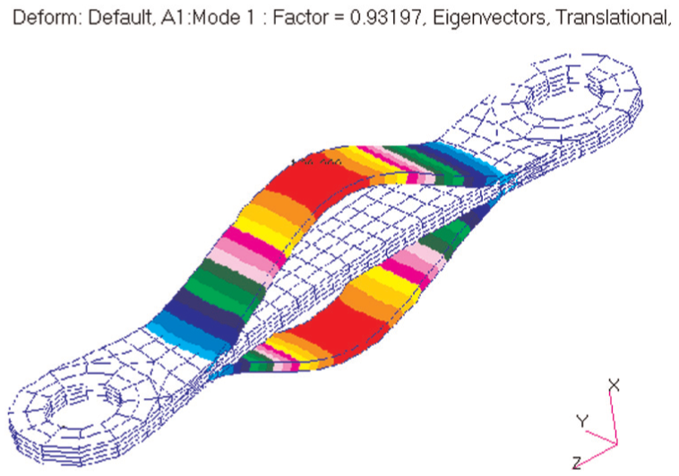
First buckling mode of the original diaphragm.
To avoid buckling destruction, an optimization measure about geometric parameters of diaphragms is proposed. The width of the diaphragm is increased from 30 to 40 mm; accordingly, the radius of the waistline of the diaphragm is increased from 523 to 820 mm. The buckling factor of diaphragm under maximum torque is optimized to 1.1092 after modification, which means the buckling destruction of diaphragm will not occur until the torque reaches 1.1092 times of maximum torque. The first buckling mode of the improved diaphragm is shown in Figure 13.

First buckling mode of the improved diaphragm.
Relationship between pretightening force and sliding torque
For the friction plate and the friction flange in the middle section, the relative sliding will occur if the friction force is greater than the maximum static friction. The taper sleeve 2 and the end cap are assembled by 10 hexagonal head bolts. Therefore, the maximum static friction is determined by the pretightening force of the bolts. To determine the reasonable range of pretightening force, it is necessary to analyze the sliding torque under different pretightening forces.
Given the increasing pretightening force FO from 70 to 85 kN, the sliding torque is obtained by contact FE analysis. In the analysis, 40 increment steps of load are adopted, including 10 assembly steps and 30 torsion steps. In the assembly steps, the pretightening force increase from 0 to the given valve. In the torsion steps, the working torque increase gradually from 0 to 34.26 kN m (the Tmax defined in equation (1)). Figure 14 presents the circumferential displacement of the friction plate and the friction flange.

Circumferential displacement of the friction plate and the friction flange: (a) FO = 70 kN, (b) FO = 75 kN, (c) FO = 80 kN, and (d) FO = 85 kN.
In Figure 14, if the relative rotational displacement between the friction plate and the friction flange is greater than zero, it means that the relative sliding occurs. It can be found that the friction plate and the friction flange begin to slide at step 27 when the bolt pretightening force is 70 kN, step 29 when 75 kN, step 31 when 80 kN, and step 33 when 85 kN. Consequently, sliding torque under different pretightening forces can be obtained, as shown in Table 3.
Sliding torque under different pretightening forces.

Based on Table 3, an empirical formula between pretightening force of the bolts and the sliding torque can be given as

where Tslide is the sliding torque and FO is pretightening force of the bolts.
It can be found that all the sliding torques are less than the maximum input torque

where TA is tightening torque of the bolts and d is bolt diameter. For the bolt of M16 × 100, d = 16 mm, the tightening torque of the bolts is suggested to be 220–280 Nm.
Fatigue analysis of the diaphragms
The diaphragms are made of 60SiMnA + 4. The material parameters of 60SiMnA + 4 are ultimate strength

S-N curve of 60SiMnA + 4.
The data provided by the manufacturer and the operation tension load of the coupling are listed in Table 4.
Operation tension load of the diaphragm coupling.

The reliability represented by the cycle number is equal to 90%. Figure 16 shows the logarithmic damage contour while Figure 17 the fatigue life contour of the diaphragm.

Logarithmic damage contour.

Fatigue life contour.
It can be seen from Figures 16 and 17 that the number of the fatigue cycle is 4.71 × 10⁹ when the survival rate of 90% is employed. It means that the fatigue properties of the diaphragms meet the requirements of the service deadline of the diaphragm coupling.
Concluding remarks
Dividing the diaphragm coupling into three substructures and considering the assembly and contact conditions properly, the stress analysis of the diaphragm coupling is completed. The results indicate that all the components of the diaphragm coupling meet the requirements of structural strength.
The buckling factor of the diaphragm is obtained. It shows that the buckling destruction of diaphragm may occur under maximum torque. A modification measure of adjusting the geometric parameters of the diaphragms is proposed and is proved to be effective.
The empirical formula between pretightening force of the bolts, that tighten taper sleeve 2 and end cap, and sliding torque is given. In order to meet the design value of sliding torque of the coupling, the range of the pretightening force and the tighten torque of the bolts is recommended. The fatigue analysis of the diaphragms is completed, and the results show that the diaphragms are competent to the designed life of the diaphragm coupling.
Footnotes
Academic Editor: Magd Abdel Wahab
Declaration of conflicting interests
The author(s) declared no potential conflicts of interest with respect to the research, authorship, and/or publication of this article.
Funding
The author(s) disclosed receipt of the following financial support for the research, authorship, and/or publication of this article: This work was financially supported by the Natural Science Foundation of ChongQing (no. cstc2015jcyjA60010) and the Science and Technology Foundation of ChongQing Education Commission (no. KJ1500929).