
Abstract
Generally, there are two alternative design approaches available to engineers: bottom-up and top-down. Considering the sharp increase in the complexity of most mechanical products, the top-down design approach is more widely adopted in the development of complex products. However, in traditional top-down design process, design parameters are communicated through single-skeleton models, and design units are strongly coupled due to the multi-dimensional complexity of products. Toward this end, a new top-down design approach based on multi-skeleton model is proposed in this article. First, in accordance with different kinds of design parameters, three major skeleton models are defined, including location skeleton model, published skeleton model, and design skeleton model. And the characteristics of multi-skeleton models are also described. Then, the top-down design process based on the multi-skeleton model is explored, especially in the multi-skeleton modeling phase. It is also illustrated in detail that how to realize design parameter transmission and design unit reuse. Subsequently, it elaborates the communicating way and structure optimization of design parameters to support parameters controlled publishing and design units reuse. Finally, a meteorological satellite and a crawler crane design cases are implemented to expound the feasibility and effectiveness of the proposed framework.
Keywords
Introduction
Recent advances in science and technology have led to a rapid increase in the complexity of most mechanical products and engineering systems,1,2 whose design needs cooperation among different groups.3–5 Traditionally, two alternative design methodologies, called top-down and bottom-up, have been used in the development of complex products.4,6–8 However, the complexity of new product development forces many companies to rethink the way they design complex products. And how to design these products in an effective and efficient way seems to be of great importance.
In comparison to bottom-up, top-down design (TDD) approach is a more natural way, which is extensively applied in the collaborative development of complex products.4,5,9,10 In TDD approach, 11 the designer first generates a rough, overall sketch of the product and its main components. Then, the designer refines the sketch to a more detailed level, sometimes in many additional sub-components levels, until the level of bottom components is reached. In this way, the complex design work of a product is subdivided gradually and recursively into several simpler design works of subassemblies and parts, which could be executed in parallel. 12 It not only reduces the difficulty and complexity of the design work but also makes design cooperation between different groups possible. The primary feature of TDD approach is the utilization of skeleton models, also called layout models.13,14 Skeleton model evolves from the abstract specification 11 that captures product structure consisting of major components and their desired interfaces, relationships, or constraints in the conceptual design phase. 4 Through skeleton models, it is able to express design intent, define reference relationship, and build product structure, realizing the communication and share of design parameters in a top-down and proactive manner.
In collaborative product development, the access to design parameters is strictly controlled and general design units are intended to be frequently reused. Unfortunately, due to the limited support of traditional TDD approach, there are still a lot of unsolved problems including single transmission path of design parameters and complex coupling relationships among design units. In such a context, the work here is exactly meant to do some further research on TDD approach to promote the development efficiency of complex products. To be specific, the breakthrough consists in providing a multi-skeleton modeling awareness and consideration for product architects and designers by incorporating product life cycle stages in an integrated and proactive manner in the early product development process. There are two key points to realize TDD of complex products. One is an integrated TDD process which can be supported by commercial design tools and data management systems. The other is a reasonable construction of skeleton models that can ensure an effective communication of design parameters. In this way, then the systematic approach to engineering design is brought to a level that provides a solid foundation for the successful development of complex products.
The remainder of this article is organized as follows. TDD based on skeleton models is analyzed, and related literature is reviewed in section “Literature review.” Some important definitions of multi-skeleton models, as well as their characteristics, functions, and representations, are introduced in section “Multi-skeleton model for TDD.” An integrated TDD process based on multi-skeleton model is established, and its mechanisms for parameter communication are discussed in section “TDD based on multi-skeleton model.” The feasibility of the proposed approach is demonstrated in section “Case study,” with a case study involving top-down multi-skeleton modeling of a meteorological satellite and a crawler crane. Conclusions and suggestions for future work are provided in section “Conclusion and future work.”
Literature review
This section states a general review of some significant research work on TDD using skeleton models and gives special emphasis on multiple skeleton modeling issues. It also provides conclusions of critical findings about the current research status and challenges in these fields.
TDD based on multi-level skeleton model
Generally speaking, in the research of TDD approach, the multi-level skeleton model is usually divided into different skeleton levels according to the product assembly structure. Its core characteristic is adopting the standard skeleton model in different product structure levels in TDD process. Liu and Jin 15 gave an overview of the literature and pointed out some problems which needed to be further researched, such as assembly model representation and engineering analysis in the transformation of parametric models to detailed models. A top basic skeleton (TBS) as the information carrier in TDD was provided.16–18 The TBS was an abstract design model at the top of each assembly structure level, defining primary functions, basic structures, global parameters, and its dependencies. Then, the whole product design can be modified, detailed, improved, and completed based on the TBS. Lan 19 used main skeleton and sub-skeleton models to determine the relative position of the assembly, subassemblies, and parts in three-dimensional (3D) space, as well as its assembly relationships and some other critical design parameters. The essence of main skeleton model can be viewed as TBS model controlling the product structure and its functions in different levels. A multi-resolution and multi-level product assembly model with distributed skeletons was provided to support collaborative top-down assembly design.9,10 Meanwhile, fine-granularity collaborative design functionalities and agent-based design variation propagation were also discussed. By combining top-down and modular design, Deng et al. 20 proposed a top-down modularization approach, which was achieved through extensible skeleton model (XSM). And XSM was developed by integrating traditional skeleton models with useful knowledge, resources, and processes. Fu et al. 21 provided an approach to establish multi-level skeleton models for associated design. In their study, the top skeleton model can be decomposed into subassembly skeleton models in a multi-discipline way. Meanwhile, a constraint network model among all skeleton models was established to realize the association or unity of design data.
TDD based on multi-function skeleton model
Furthermore, the studies on TDD approach focus not only on multi-level skeleton models but also on the multiple functions of skeleton models. A neutral model for representing some conceptual design information of a product was introduced in the framework of STEP (STandard for Exchange of Product Model Data) approach.22,23 Such a model was able to capture the key aspects of design intent in addition to the shape representation. Mantripragada and Whitney 24 presented a TDD approach to link logical design of assembly layouts with key characteristics, assembly sequences, and choices of mating features. The datum flow chain was provided to capture the fundamental product structure. Csabai et al. 14 used design spaces with simple geometry and kinematic connections to present a product in top-down 3D layout design. Bronsvoort and Noort 25 described a multiple-view feature modeling approach to support conceptual design, assembly design part detail design, and part manufacturing planning. Interfaces and connections between components are also discussed. Hwang et al. 5 proposed a neutral reference model, consisting of a neutral skeleton model and an external reference model, as a new medium for sharing and propagation of engineering change information in a distributed collaborative design environment. Xu et al. 26 introduced a product modeling framework based on interaction feature pair. This framework supported TDD, whereas it focused on part modeling stage. Mun et al. 4 proposed an approach to share a skeleton model among collaborating companies. Using this model, participating companies can share essential data required for the detail design of components, while ensuring security of their intellectual property. Wang 27 presented a novel hybrid modular design strategy, in which the common assembly interface geometry was used as an essential component so that all product modules can be assembled to it. The method kept part of TDD process and also reduced the interlinkages among the modules. Demoly and colleagues28–30 introduced assembly skeletons so as to provide a new support for the product geometric modeling phase. Assembly skeleton can be considered as the first geometric element to which the designers can allocate and define part volume and geometry. And they also enabled the centralization of relational information for the various assembly states of the product in a proactive and top-down way. In the above-mentioned research, there was one skeleton within one design unit. The inheritance mechanism was realized by the detailed relationships of geometric features, constraints, and parameters. These relationships existed between not only parent–child but also brother skeletons, making designers to deal with them tediously and redundantly. Xiang and Tang 31 presented a TDD approach based on double skeleton model and analyzed how it solved the reference reuse problem in product design. Its key point was to establish the locating skeleton in the top-level of complex products in order to manage and control subsystem skeletons. And design intent was transmitted and shared through the design skeletons in subsystem design. However, this approach was not suitable for multi-level complex products because it was not able to design lower-level system by this way. Chen et al. 12 explored the novel assembly design process, assembly model, and inheritance mechanisms that were required by next-generation computer-aided design (CAD) tools in order to support top-down product design effectively. In their research, a multi-level assembly model, including shape skeleton, layout skeleton, and detailed model, was put forward to capture the abstract information, skeleton information, and detailed information. The shape skeleton shared between the parent–child design units does not contain all the inheritance information. Therefore, designers are still required to deal with many constraint relations of the multi-level assembly model. 32
Synthesis
In conclusion, the study on TDD approach is still preliminary. And traditional TDD is often based on single-skeleton model, even though it can be established from the perspective of multi-level or multi-function.
There are two major problems with the works described above. The first one is the absence of multi-skeleton models dedicated to TDD and the second is the insufficiency of parameter transmission mechanisms for TDD. Specifically, on one hand, it is about the publishing of design parameters in collaborative product design. Design units in the same design level share all the design parameters published from their parent design unit, resulting in an ineffective control of access to design parameters. On the other hand, it is about the reuse of design units in product family design. Frequent reuse of common design units could bring related design references together into the new product development, causing confusions of reference relationships in the new product. Furthermore, some works discover and establish significant concepts about skeleton functions, while others mainly focus on the representation of design information in some specific design phases.
Therefore, the aim of multi-skeleton models and supporting mechanisms presented in this article is to solve these two major problems, which account for the very obstacles of implementing CAD tools supporting TDD. Generally speaking, this article provides a multi-skeleton model for TDD in the development of complex products. That is to say, it establishes multi-level skeleton models in different product structure levels in order to realize hierarchical control of design parameters.
For the multi-skeleton model, all the design information is classified and packaged rather than piled up together, making design intent communication simple and clear. Particularly, a separated skeleton responsible for inheritance is directly assembled to child design which replaces tedious correlation manipulation of geometric features and constraints, making product design and reuse of design units more easily. And also, it establishes multi-function skeleton models for different design units so as to manage design parameters in categories, making them published in control.
Multi-skeleton model for TDD
In TDD process, it must first define the product structure and design intent. Next, the design intent captured by skeleton models can be communicated throughout the product structure. And then product design is able to be organized in a proactive top-down manner. The following will further discuss the product structure, design parameters, and especially the multi-skeleton models.
Product structure
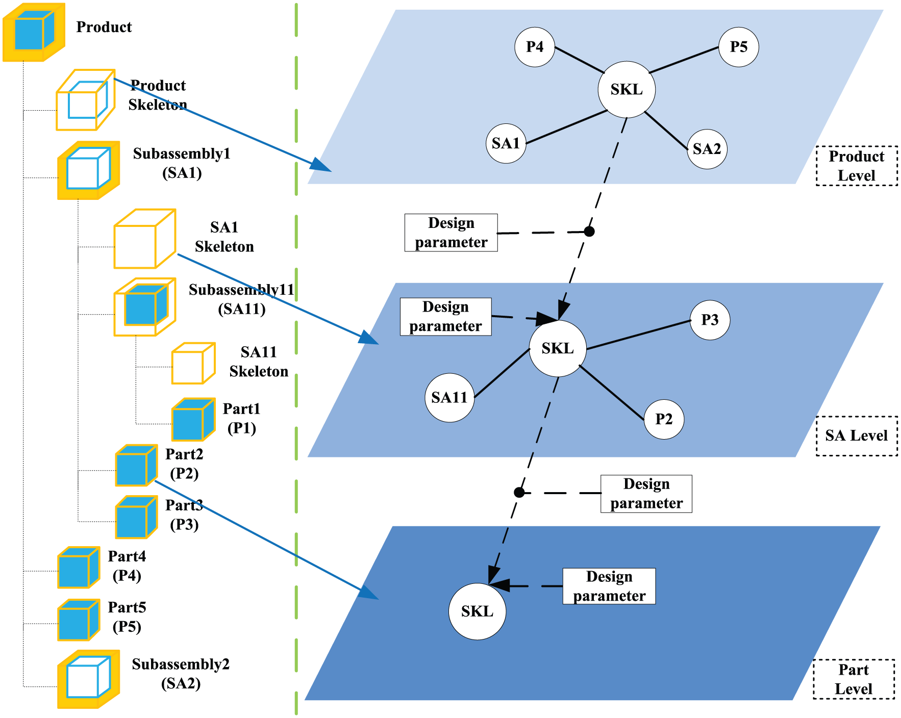
The hierarchical structure of product descriptions has been presented as a technique for representing complex products,33,34 which is designed as a tree-based structure consisting of nearly decomposable systems 35 in a hierarchical manner. Figure 1 shows how a product is decomposed into several subassemblies, which are decomposed further into different parts. 36 The physical elements used for realizing and materializing the required functions are called design units. 14 By the definition, a design unit can be a product, a subassembly, or a part. Design unit of product (Pro) represents the object to be designed and is represented at the top of the data structure. It can be considered as the final state of the assembly process from a design point of view. 28 Design unit of subassembly (SA) means the assembly of related parts and secondary subassemblies with specific functions and interface features. Design unit of part refers to the minimum design object that cannot be further decomposed in the design process.

Hierarchical decomposition of complex products for top-down design.
Design parameter
Design intent, which can be defined as functional requirements such as a set of geometric and functional rules that must be satisfied, 23 is usually represented by parametric information, including constraints, parameters, design history, and component features. 4 Here, according to different types of parametric information, we formally define three kinds of design parameters including interface and location design parameter, key product design parameter, and general product design parameter. They demonstrate the feasibility of capturing key aspects of design intent for multi-skeleton models in TDD process:
Interface and location design parameter (LP). It represents interface geometries, location features, and mechanism kinematics of design units in different levels of the product structure. It usually refers to the type and form of interface and location, the datum of spatial orientation, the constraints of assembly, the features of connection and motion, and other characteristics. LPs are always established and published by the parent design unit.
Key product design parameter (KP). It represents the key product design information in different levels of the product structure, which must be inherited from the parent design unit. It often refers to the crucial features of design units such as space claims, geometric shapes, and assembly references. KPs are also established and published by the parent design unit.
General product design parameter (GP). It represents the general product design information in different levels of the product structure, with which the design task of a design unit will be completed. It often refers to more detailed design information that will be used in the detail design phase. GPs are established and published by the design unit itself.
Multi-skeleton model
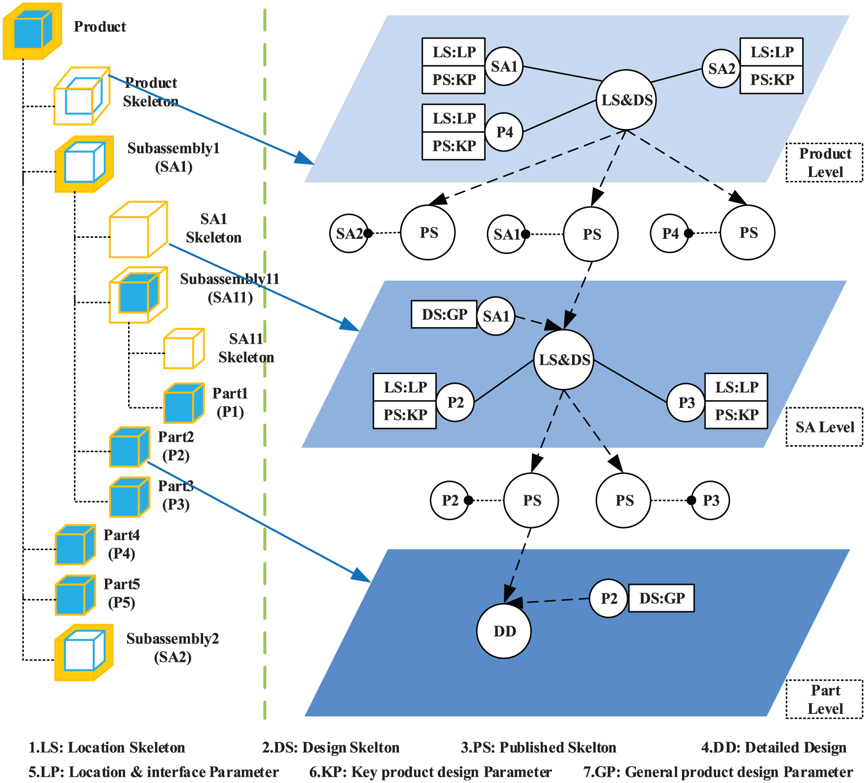
The skeleton model contains the fundamental CAD structure of a product that is intended to be used in the detailed modeling phase.4,5,37 It describes product structure and functions in the abstract specification through a collection of basic geometric modeling primitives such as points, curves, planes, and sketches. As the framework of a product, the subassemblies and parts must be created and assembled referring to the skeleton model. Therefore, the skeleton model must be able to deal with these kinds of design parameter propagation and change. Here, in accordance with the roles or functions a skeleton model can play or realize, we formally define three kinds of skeleton models including location skeleton model, published skeleton model, and design skeleton model. They are core of the proposed approach and the schematic diagrams of them are shown in Figure 2:
Location skeleton model (LS). It is the skeleton model that controls and conveys LPs for design units in different levels of the product structure. It is responsible for determining spatial positioning references, location features, interface types and forms, assembly, and mating rules of design units in product levels and subassembly levels. LS is established and controlled by the parent design units, containing LPs of their child design units. The essence of LS is 3D layout model 12 or assembly interface geometry,27,28 with the key feature of designing and controlling layer by layer to ensure the match and consistency of interfaces and locations between different design units. However, in the traditional skeleton model, the interface and location features are often established in the top-level design units. In the CAD environment, LS is saved as a part file.
Published skeleton model (PS). It is the skeleton model that controls and conveys KPs which are published from the parent design unit to its child design units. It determines space claims, geometric shapes, and assembly references of design units and is to manage, control, convey, and share KPs between design units. So, it is similar in concept to shape skeleton 12 or design space 14 in other works. In the design, PS is established and controlled by the parent design units, and the child design units must inherit and refer to its own PS in order to realize top-down control. So, it expresses the communication and control of the parent design unit, as well as the inheritance and reference of the child design unit. The core feature lies in the precise publish of critical design information layer by layer, making the child design units only obtain their own skeleton models. This enables the access to critical design information to be effectively controlled. However, in traditional skeleton model, all the child design units can share the information from the same parent design unit, easily bringing about the leaks of design intent and circular references. In the CAD environment, PS is also saved as a part file.
Design skeleton model (DS). It is the skeleton model that designs and assemblies the skeleton models with comprehensive design parameters including LPs, KPs, and GPs. It inherits the design parameters from its parent design unit and publishes the required design parameters to its child design units. DS is the core of multi-skeleton model in TDD, mainly for skeleton design and assembly. It contains LS of itself, PS from the parent design unit in upper level, PSs to the child design units in lower level, as well as some other features it has established. In the CAD environment, DS is saved as an assembly file on assembly level and a part file on part level.

Multi-skeleton model: (a) location skeleton, (b) published skeleton, and (c) design skeleton.
Concept formalization
A lot of concepts have been defined in the prior discussion. In order to make these concepts more concrete, a symbol system is introduced to formalize them. Designers in different design levels can easily make sure what design activities they should conduct according to the formalized language. Besides, they may extend these formalizations with regard to their own design situations.
A complex product contains m subassemblies and n parts. In its ith assembly, there are l parts. Therefore, the formalization of product structure is as follows


As discussed above, different skeletons represent different design parameters, which can be roughly formalized as follows


Combining multi-level product structures and multi-function skeleton models, key concepts of multi-skeleton model for TDD in complex products are further formalized in detail as follows
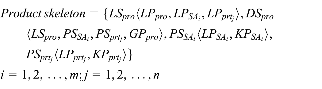
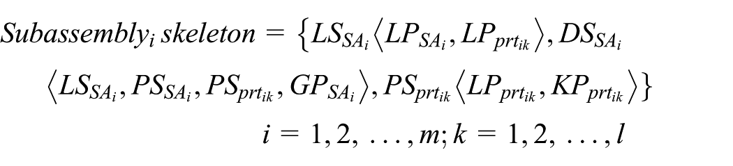

where different subscripts are used in the concept formalization procedure to distinguish each other in the same concept. LS, DS, and PS are established successively. For design units in product and subassembly levels, PS is an empty skeleton in DS until PS is fully designed. PSs in the product level are directly designed and published. However, in the subassembly levels, they must first be assembled in each DS and then child PSs can be designed. Design units in the part levels just assemble their own PS to design in detail.
TDD based on multi-skeleton model
TDD process
The development of complex products is a gradual process of improvement and refinement from the design of the abstract to the concrete. It can be divided into five phases including functional design, conceptual design, embodiment design, detailed design, and engineering analysis. 13 In order to emphasize skeleton modeling, we roughly distinguish three main design phases: master plan, skeleton modeling, and detailed design, 9 as shown in Figure 3.

Top-down design process based on multi-skeleton model.
Phase I of Figure 3: master plan
It is the start of product design, including three key steps: functional description, conceptual design, and structure decomposition. Master plan mainly contains some primary and critical product characteristics such as LPs and KPs and describes the product prototype and assembly constraints. This phase inputs product information from customer requirements and engineering requirements and outputs the overall layout model. For the development of complex products, it requires different design levels, such as product and subassembly levels, formulate their own master plans in order to reduce design complexity. Therefore, there are two kinds of master plans including product- and subassembly-level master plans. Accordingly, the overall layout model also contains a layout hierarchy. This process is recursive until a set of layout models are formed. However, in traditional design, it often only drafts a product-level design plan to instruct the whole design.
Phase II of Figure 3: skeleton modeling
A skeleton is a special file with the specific purpose of providing the framework for a design unit. In the skeleton modeling phase, it establishes multi-skeleton models for different design units based on the output of corresponding layout models. Here, layout models should be mapped to skeleton models to realize that layout parameters drive skeleton features easily and automatically. In other words, multi-skeleton model can be declared to the related layout model so that the parameters in the layout are visible to the skeletons. It is the key to realizing the feature-driven and parametric design. This process will be recursive until a set of multi-skeletons are formed. The output is a multi-skeleton model, which could be a product-level one, a subassembly-level one, or just a part-level one. However, in traditional skeleton modeling phases, it often only establishes a top-level skeleton model either in the product level or in the sub-levels, without distinguishing different kinds of design parameters in the skeleton model.
Phase III of Figure 3: detailed design
It fully accomplishes the detailed design of design units. In this phase, the main activities include establishing the detailed feature models of all design units and finalizing the assembly relationships with assembly constraints and parametrical constraints. 9 The input of multi-skeleton model is not sufficient to complete the whole detailed design task without taking into account the relevant requirements posed by manufacturability, serviceability, cost, strength, and other similar considerations. 11
Skeleton modeling process
The key characteristic of TDD based on multi-skeleton model lies in its skeleton modeling process (Phase II of Figure 3). Meanwhile, the above design phases are in general iterative and recursive. Therefore, when looking at Figure 4, it becomes easier to make significant comparisons between these two skeleton modeling processes. Surely, it shows the primary characteristic in brief, and there are more than that.

Comparisons between different skeleton modeling processes.
Traditional skeleton modeling process
The traditional skeleton modeling process is shown in Figure 5. Design parameters are transmitted from top-level design units to sub-level design units by the published geometry. The sub-level design unit establishes its own skeleton model, accepting design parameters from the top-level design unit by copy geometry. Design parameters are further complemented on the basis of the sub-level design requirements and then continue being published to the sub sub-level design units until the bottom-level ones, such as parts.
Traditional skeleton modeling process.
Multi-skeleton modeling process
Unlike traditional skeleton modeling, in multi-skeleton modeling process (Figure 6), it establishes multi-level skeleton models to realize hierarchical control of design parameters and multi-function skeleton models to manage design parameters in categories. To be specific, on one hand, it adopts hierarchical and parametric modeling approach in order to standardize the skeleton modeling process. It expresses the multi-level skeleton modeling process of all design units in the product structure, embodying top-down control layer by layer. On the other hand, according to the different roles of multi-skeleton models in the skeleton modeling process, it classifies into three kinds of skeleton models. It expresses the multi-function skeleton modeling process of one design unit in the hierarchical product structure, embodying the multiple functions of skeleton models.
Multi-skeleton modeling process.
Therefore, Phase II of Figure 3 can be furthered decomposed into three steps:
Step 1. Establish LSs of product- and subassembly-level design units, respectively. Then, create interface and location features of sub-level design units so that the parent design unit can control LPs of its child design units.
Step 2. Establish DSs of product- and subassembly-level design units, respectively. Then, assemble its own LS, respectively, in order to provide with LPs to help create some key features later. These key features are KPs that child design units must inherit from its parent design unit.
Step 3. As for different design units, in this article including product-, subassembly-, and part-level design units, skeleton modeling process is distinguished from each other. Establish PSs of sub-level design units directly in DS of the product-level design unit, as well as some other features of it. And then create key features in each PS so that the product-level design unit can control KPs of its child design units. However, subassembly-level design units must first assemble their own PS from parent design units, acquiring KPs. Then form complete design parameters together with their own GPs. Finally, conduct design activities for DS, establishing PSs of sub-level design units as well as some other features represented by GPs. As for part-level design units, assemble each PSs, and conduct detailed design tasks directly to meet design requirements.
Parameter transmission structure
In TDD, interrelated design parameters form a parameter transmission chain and then all parameter transmission chains are composed into a complex parameter transmission structure.3,38 A critical aspect of TDD approach is the communication of design parameters from a central location, such as layouts or skeletons, to all design units. 8 In traditional design process, it mainly uses copy and publish geometry features to document and distribute design parameters. And different design parameters are packaged all together and shared in a form of geometry features attached to design units. It results that in a product model tree, designers cannot distinguish different features or parameters, such as geometry shape, assembly relationships, datum, and references.
In TDD based on multi-skeleton model, communication of design parameters can be divided into two categories, inside and between design units. It still adopts geometry features to realize the transmission of design parameters inside design units. However, between design units, it mainly depends on functional skeleton models to communicate different kinds of key design parameters. Therefore, the task is to decompose the internal single-skeleton model and optimize the external network parameter transmission structure. It aims to form a standardized hierarchy parameter transmission structure better supporting multi-skeleton modeling. Here, the article only further discusses the communication between design units in order to elaborate how to achieve hierarchical control of design parameters and manage them in categories though multi-skeleton models.
In traditional and typical CAD assembly modeling process, there is no skeleton element between design units, causing the complex interrelationship and strong coupling among design units, as shown in Figure 7(a). In single-skeleton modeling process, it establishes a basic skeleton model in top-level assembly, and all the subassemblies are designed referring to the top-level basic skeleton, as shown in Figure 7(b). In this process, the interrelationships among the subassemblies are transformed into the assembly constraints and relationships between the subassemblies and the skeleton element, reducing the coupling of subassemblies. Furthermore, as for products consisting of complex and multi-level product structures, its subassemblies are also complex enough to require that the skeleton models be established not only in the product top-level but also in the subassembly top-level, as shown in Figure 7(c). Through establishing skeleton layer by layer, the coupling of different parts is further reduced. In traditional TDD, skeleton models are designed as general assembly interface geometries as seen in Figure 7(b) or assembly design models with a multi-level structure as seen in Figure 7(c). Considering multiple collaborative design groups working together on complex products, sharing and exchanging design parameters become a very sensitive issue because of parameter consistency and protection. 3 That is to say, when communicating design parameters among design units, the child design units share all the design parameters published from the parent design unit in the upper level. However, for every child design unit, only part of the design parameters belongs to it. So, it is not helpful to protect design knowledge 39 of the other child design units in the lower level. Besides, while establishing skeleton models, the strong coupling of the upper-level and lower-level design units lead to the complexity and redundancy of reference relationships among the lower-level design units. This is also not helpful for general modules to be reused in product family development.

Parameter transmission mode: (a) no skeleton model, (b) single-skeleton model, (c) multi-level skeleton model, and (d) multi-skeleton model.
PS is the key to solve above problems. In TDD process based on multi-skeleton model, design of the subassemblies/parts will not refer to the top-level basic skeleton of the product/subassemblies. Instead, every subassembly/part in the lower level is designed referring to PS published from its parent design unit, ensuring the design parameters published in control. In addition, LS and DS of every design unit are not transferred from upper level to lower level. However, LPs and KPs of every design unit are transmitted through PS layer by layer. That is to say, the parent design unit establishes PSs for its child design units, as seen in Figure 7(d), and all child design units assemble their own PS as design references.
In multi-skeleton modeling process, the interlinkages among design units are replaced by the reference relationships between design units and multi-skeleton models. Therefore, it minimizes unwanted parent–child relationships among major design units, ensuring relative independency of design units and easier reuse of general modules. And due to the establishment of PSs, every child design unit can only obtain its own design parameters from the parent design unit. These design parameters do not include its brother relationships any more. At the same time, PS representing KPs and LS representing LPs are still controlled by the parent design units. Besides, the child design units must inherit their own PSs and match the interface and location features in their parent’s LS. So, it also ensures control in a top-down manner. In conclusion, it realizes TDD based on continuing to minimize complex interdependencies among major design units of product.
Parameter transmission rules
Design changes can propagate along a defined path and trigger a rule. 40 In order to better support multi-skeleton modeling for TDD, it is critical to optimize traditional parameter transmission structure, as the dashed boxes shown in Figure 7(c) and (d). Here, the article provides two basic rules in Figure 8(a):
Rule 1. If there is interdependency between the upper-level and the lower-level design units, then the design parameters in the lower-level design units must be driven by those in the upper level. It ensures design parameters communicated layer by layer in a top-down way, as shown in Figure 7(d).
Rule 2. If there is interdependency among design units in the same structure level, then extract the common design parameters and convert to the relationships between the upper-level and the lower-level design units. It makes design units in the same structure level controlled separately by their common design unit and minimizes the coupling between them, as the dashed arrow shown in Figure 7.
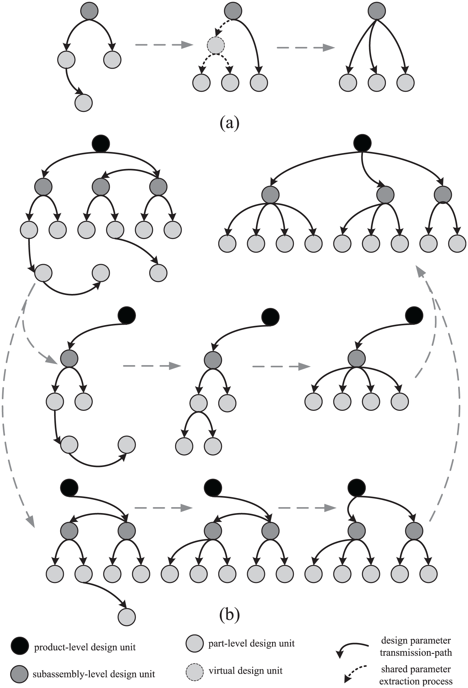
Optimization of parameter transmission structure: (a) key parameter extraction and (b) parameter transmission structure optimization.
In Figure 8(b), it presents the traditional parameter transmission structure and the optimized one. It also describes the process of how to convert the lateral transmission structure to the longitudinal tree-based structure. In the optimized structure, design parameters are only allowed to be transmitted in a longitudinal way. Design parameters that have lateral transmission relationships can establish relations with the upper-level design units, until the product-level one, by referring to the above two basic rules.
Design unit reuse
The main design process of a complex product from master plan to detailed design with the proposed multi-skeleton TDD framework is shown in Figure 9. The reuse of design unit and its skeletons is carried out in the framework:
Design unit reuse. If an existing design unit is reused, the design unit with its DS is directly assembled in the parent assembly, and the PS is assembled in the parent assembly DS.
DS reuse. If the DS is directly reused, it means that the design unit is reused. If an existing design unit needs to be modified to produce a similar design unit, the DS is selected from the skeleton library and saved as a new file. It is necessary to determine the LS and PS to be reused, modified, or redesigned.
LS reuse. With the master plan, the structure is constructed by means of which the main spatial arrangement of LS is achieved. If the location information of a new design unit is the same as an existing one, the LS is selected from the skeleton library and assembled in the DS of the new design unit. If there is a similar one, after being assembled in the new DS, the LS is modified and saved as a new LS.
PS reuse. If the same or similar PS exists in the skeleton library, the PS can be directly reused or modified in a new design unit development. If the new design unit contains an existing or a similar sub-design unit, the PS is directly reused or modified. The modified PS needs to be saved as a new file.
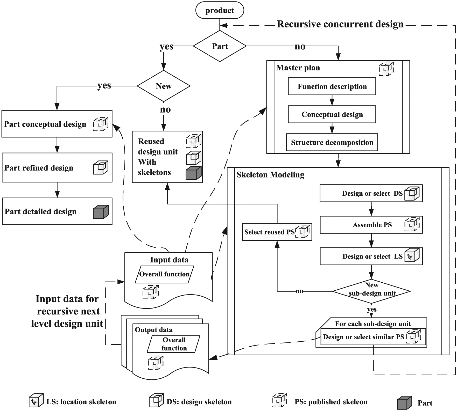
Flow chart of complex product TDD.
Case study
In modern manufacturing enterprises, design tasks for complex products are mainly carried out with mainstream CAD systems such as PTC’s Pro/E, Siemens’s NX, and Dassault’s CATIA, which effectively support solid models, features, and constraints. The proposed multi-skeleton modeling framework can be performed with those CAD systems. A meteorological satellite and a crawler crane use Pro/E and CATIA as design tools to illustrate the usefulness of the approach for complex product design, respectively.
Case 1: a meteorological satellite design
This case aims at providing technology support for the establishment of satellite digital and collaborative design platform. In this section, a meteorological satellite design case is introduced to illustrate the usefulness of the proposed framework. The product selected has moderate complexity to ensure that efforts are focused on multi-skeleton modeling process of TDD approach, rather than spent on attempting to understand the product. CAD software Pro/E is the tool for modeling in this case.
Multi-skeleton modeling process
The meteorological satellite includes the satellite level, the module level, the deck level, and the equipment level, as shown in Figure 10. Here, in this case, only the first 3 levels are considered. Figure 11 shows a brief process of multi-skeleton modeling. The following will take the antenna module as an example and discuss the process in detail.

Structure of the meteorological satellite.

Multi-skeleton modeling process: (a) satellite DS, (b) antenna module PS, (c) antenna module DS, (d) roof PS, (e) roof detailed design, and (f) roof assembly.
First, create the satellite assembly and then create the satellite LS in it. In the satellite LS are interface and location features of the satellite and its two modules, the propelling module and the antenna module. Create the satellite DS and assemble its LS (Figure 11(a)). In the satellite DS, create PSs of the propelling module and the antenna module separately (Figure 11(b)). Second, create the antenna module assembly and obtain its LPs from the satellite LS. Then create the antenna module LS in its assembly. In the antenna module LS are interface and location features of its floor, roof, and side plates. Create the antenna module DS and assemble its LS and PS (Figure 11(c)). In the antenna module DS, create PSs of its floor, roof, and side plates (Figure 11(d)). Finally, create assemblies of all decks, for example, the roof of the antenna module. Create the roof assembly and obtain its LPs from the antenna module LS. Then create the roof LS in its assembly. In the roof LS are interface and location features of equipment installed on it. Create the roof DS and assemble its LS and PS. In the roof DS, create PSs of equipment and accomplish detail design of the roof (Figure 11(e)). Without considering equipment, it is not necessary to create DS and LS in the roof design of the antenna module in the bottom level. Just assemble the PS and accomplish detail design.
Modeling process comparison
In traditional skeleton design, first, create the satellite skeleton in the assembly, mainly including point, line, plane, and coordinate system of the satellite, the propelling module and the antenna module, as well as their profiles. Then, the satellite designer publishes design references to the module designers by publish geometry. And the module designers receive their design references by copy geometry and continue further design. Taking the antenna module for example, the designer should create geometry shape, references, and datum of the floor, roof, and side plates in the antenna module. And so forth, accomplish the final detail design of the decks. In this modeling process, features, references, and datum of two modules are all created in a single satellite skeleton and communicated through copy geometry and publish geometry. Two modules are designed, refined, and improved on the basis of the whole satellite skeleton. This will bring about some major problems. On one hand, it is likely to cause the leak of design intent in the satellite level. On the other hand, it may cause an inaccurate grasp of required design intent for modules, as well as the interactive design and circular reference among modules. Besides, due to the use of copy and publish geometry, the design parameters are comminuted in data packets. Designers cannot clearly distinguish from different kinds of design parameters. Furthermore, it will be more serious in collaborative design and module reuse in product family design, such as design knowledge leak and complex reference relationships.
In multi-skeleton design, first, create the satellite LS as dashed box shown in Figure 11. Then create the satellite DS (an empty skeleton in initial design stage) and assemble its LS. Finally, create PSs of the propelling module and the antenna module, resulting in a complete satellite DS (Figure 11(a)). Each design unit is designed referring to the PS (detail design of the roof shown in Figure 11(e)) and assembled referring to the LS (Figure 11(f)). So, there is no interdependency among design units in the same design level. That is to say, establishment of published skeleton of each design unit realizes the control of access to design parameters, ensuring relative independence of each design unit. At the same time, the multi-skeletons act as a central location for storing and with a hierarchy structure to communicate design parameters. So, the interdependencies among design units are sharply reduced, making general design units reused more easily.
In this satellite design company, the multi-skeleton and traditional skeleton TDD approaches were compared for the same satellite design. As shown in Table 1, the advantage of the multi-skeleton modeling framework is clear.
Comparison of the multi-skeleton and traditional skeleton TDD approach.

Design parameter transmission
A clear and hierarchical product structure is very important for multi-skeleton modeling, offering the capacity to manage large models effectively. 41 And the design parameter transmission mechanisms are used throughout the entire design process. In fact, in the propelling module, there is a loaded cylinder in the middle that can affect the design of laminates and partitions (Figure 12). In modeling process, according to parameter transmission rules, the loaded cylinder skeleton is designed in DS of the propelling module and published as KP to the laminate and partition design level. Therefore, the design of instrument mounting plates, tank mounting plates and partitions is referenced to the loaded cylinder skeleton.

Loaded cylinder skeleton as design reference.
Another issue is design change propagation, 42 which is challenging in multi-skeleton modeling process. In the roof modeling process of the antenna module, designers obtain the roof PS to complete detailed design. For example, thickness of the roof, d, is a KP, determined by designers of the antenna module. Then if d is to change from 30 to 50 mm, detailed design can be automatically changed to satisfy the requirement (Figure 13(a)). However, diameter of the bore in the roof, D, is a GP in the roof DS, determined by designers of the roof. So, if D is to change from 200 to 300 mm, detailed design of the roof can be changed independently (Figure 13(b)). And this design change will not affect the others. Another design change is about LS (Figure 13(c)). Certain equipment is installed in an instrument mounting plate of the propelling module according to the coordinate system ASC0. Since its LP is designed in LS and determined by the instrument mounting plate designer, if it is to change from ASC0 to ASC1, the equipment can be automatically changed.

Design change propagation: (a) design change of PS, (b) design change of DS, and (c) design change of LS.
Case 2: a crawler crane
Large tonnage crawler crane is extensively used in the areas of construction, nuclear power, and wind energy for the capability of traveling with a large tonnage load. It has characteristics of high technical value, long development lead time, and multi-level hierarchical structure. Thus, as a typical and complex product using CATIA tool, a 500-ton crawler crane is illustrated with the proposed multi-skeleton modeling approach. As shown in Figure 14, there are four hierarchical levels of the 500-ton crawler crane structure.

Structure of the crawler crane.
We take the whole crawler crane, the lower works, the left crawler, and the left crawler frame as different product structure level instances to illustrate the multi-skeleton modeling process. The recursive design process for the large tonnage crawler crane is similar with the meteorological satellite design, shown in Figure 15. First, establish the entire crawler crane assembly and then establish the crane LS in it. LS is interface and location features of the crane and its three subassemblies are the lower works, the upper works, and the main boom. Establish the crane DS and assemble its LS. In the DS, establish PSs of those three subassemblies separately. Second, establish the lower works assembly. Then establish the lower works LS in its assembly. In the lower works LS is interface and location features of its left crawler, chassis, and right crawler. Establish the lower works DS and assemble its LS and PS. Third, the left crawler design is carried out in the same way recursively. Finally, for the left crawler crane, it is not necessary to create DS and LS. Just assemble the PS and accomplish detailed design.

Multi-skeleton modeling of a 500-ton crawler crane.
Conclusion and future work
In this article, a multi-skeleton model for TDD of complex products is introduced. The proposed multi-skeleton approach can be viewed in two aspects, multi-level skeleton modeling and multi-function skeleton modeling, which is distinguished from traditional skeleton design approach. In order to support multi-skeleton modeling, TDD, and skeleton modeling process, parameter transmission structure and rules are refined from the traditional design. And three fine-granularity functional skeletons including LS, PS, and DS are core features in multi-skeleton model approach. From a design point of view, some promising and challenging issues have been tackled in the proposed approach, such as the problems of controlled publishing of design parameters in collaborative product design and reuse of design units in product family design. Our future work includes relationships among product complexity, skeleton partition granularity, and design redundancy; problems of design conflicts resolution and design changes propagation in collaborative TDD of complex products; and optimizing the transferred parameters and assembly sequence based on those parameters.
Footnotes
Acknowledgements
The authors express sincere appreciation to the editors and the anonymous referees for their helpful comments to improve the quality of this article.
Academic Editor: Ismet Baran
Declaration of conflicting interests
The author(s) declared no potential conflicts of interest with respect to the research, authorship, and/or publication of this article.
Funding
The author(s) disclosed receipt of the following financial support for the research, authorship, and/or publication of this article: This research was supported by National Natural Science Foundation, China (Nos 51475290 and 51075261), Research Fund for the Doctoral Program of Higher Education of China (No. 20120073110096), and Shanghai Science and Technology Innovation Action Plan (No. 11DZ1120800).