
Abstract
Flexible dynamic analysis is a critical process in designing offshore wind turbines that are composed of several huge components. This process was implemented with a hybrid method of finite element multibody system using commercial software in this article. Based on this method, the tower and blades were modeled as flexible components using three-dimensional solid elements. The effect of flexible deformation of the tower and blades on the global motions of the floating wind turbine was investigated by comparing the simulation results from the flexible body modeling with those from the rigid body modeling. The tower, blades, and spar platform were divided into sections according to the geometry configuration of the 5-MW OC3-Hywind floating wind turbine. The time- and position-dependent loads, coming from the wind, wave, and mooring system, were expressed approximately with respect to the divided sections. The relationships between the global motions and the external loads were studied, which indicated that the wind loads had dominant influences on the translational motions and the rotational motions were mainly generated by the propagating waves.
Keywords
Introduction
As issues of the environmental pollution and energy shortage being more and more serious, lots of countries harbor the ambition on the development of renewable energies. The wind, as one kind of the renewable energy, has been used to produce electricity by land-based wind turbines for decades. Because the wind energy is more available nearby the offshore than land, the floating wind turbines draw worldwide attention and grow vigorously in recent years. 1 Although the global economic recession decelerates the installation of the wind turbines, the technical researches have no intension of slowing down. A liquid-cooling system for the direct-drive generator was designed to satisfy the requirement of the power-increasing of the wind turbines. 2 Motions of the wind turbine based on a truss spar were compared with those based on a classic spar by Wang et al. 3 using ANSYS software. Numerical modeling of a spar platform tethered by a mooring cable was established by Zhu and Yoo 4 using MATLAB code. The global motions of the floating spar were studied under effects of the ocean wave and current. The dynamic responses of a spar-type offshore wind turbine were studied by Jeon et al. 5 using ANSYS. The rotor was simplified using the lumped mass method and the wind loads were ignored in the analysis. Actually, due to the difficulties in applying the wind and wave loads on the huge floating wind turbine, the real test is hard to be proceeded with full-size model by now. Although the reduced model was tested by real experiment,6,7 the reduced blades and tower were too short to have flexible deformation that indeed exists in full-size floating wind turbines. One motivation of this article is to reveal the influence of the flexible deformation of the tower and blades on the global motions of the floating wind turbine. This investigation was conducted by comparing simulation results from the flexible body modeling with those from the rigid body modeling. In addition, the wind loads are quadratic function of the wind speed, which is an index function of the vertical height. Because the position of one blade changes periodically during normal operation, the wind loads are unstable and changes constantly with the rotation of the rotor. The floating platform aggravates instabilities further compared with the land-based wind turbine. Therefore, the other motivation focuses on the relationship between motions of the floating wind turbine and the external loads coming from wave, wind, and mooring system during the normal operation.
However, the dynamic analysis of the floating offshore wind turbine relates to the flexible multibody dynamics, hydrodynamics, aerodynamics, and so on. There is no acknowledged commercial software to cover so many fields by now. Although the GH bladed is used to simulate the land-based wind turbines, 8 it has not been recognized on the simulation of the floating wind turbines. Some modeling of the floating wind turbine is created using ANSYS software, but the wind loads are either ignored or replaced with one concentrated forces in the published papers.3,5 Meanwhile, the flexible deformation of the tower and blades is ignored. The National Renewable Energy Laboratory (NREL) developed Fatigue, Aerodynamics, Structures, Turbulence (FAST) system to analyze the floating wind turbines. 9 The modeling of the 5-MW OC3-Hywind floating wind turbine was generated by NREL. 10 Based on the geometry of the 5-MW wind turbine, a hybrid method of finite element multibody system (MBS) is proposed in this article to analyze the floating wind turbine using commercial software.
Automatic dynamic analysis of mechanical systems (ADAMS) is used to analyze a system interconnected by several rigid bodies. 11 And the finite element method (FEM) is used to analyze the flexible deformation of a single component12,13 and to deal with nonlinearly hydrodynamic loads.14,15 Therefore, the flexible deformation of the tower and blades can be reflected by a method, which combines the MBS with FEM. This method was verified in modeling the system of the aircraft and rocket, respectively,16,17 and is cited to model the floating wind turbine in this article. First, the tower and blades were pre-processed in PATRAN and analyzed in NASTRAN.18,19 The tower and blades were divided into sections according to the geometry of the 5-MW wind turbine. After that, these processed flexible components were put back to ADAMS to compose the flexible wind turbine. The wind loads were time- and position-dependent and expressed using concentrated forces in ADAMS. One kind of multi-point constraints (MPC) was used to distribute the concentrated forces on the front surfaces of the blades and tower. The connection between the rigid and flexible components was completed by other kind of MPC. The verification of MPCs was illustrated by Freed and Babuska 20 and Kuratani et al. 21 in the study of the piezoelectric structures and spot welds, respectively. The spar modeling also was divided into sections to express the time- and position-dependent wave loads. After that, the forces acting on sections were added up according to the strip theory. Motions of the wind turbine by the rigid multibody modeling were compared with those by the flexible multibody modeling. The comparison revealed that the flexible deformation of the tower and blades affects the motions of the pitch and surge and has little influence on the heave motion. The relationship between the motions of the spar and the propagating waves were studied, which indicated that the wind loads have dominant influence on the translational motions and the rotational motions are mainly generated by the propagating waves. The simulation results can be valuable references for the design of the floating wind turbine. In addition, the proposed hybrid method of finite element MBS can be used to analyze the floating wind turbine installed on a spar platform.
Modeling of floating wind turbine
Seven components, which include blades, hub, nacelle, tower, and spar, are connected by fixed and revolute joints to compose a classical flexible MBS, as shown in Figure 1.

Block diagram for the system of floating wind turbine.
Motivation and assumption
The offshore wind turbine installed on a floating spar platform is a complex flexible MBS, and the motivations of this article are (1) to reveal the influence of the flexible deformation of the tower and blades on the global motions of the floating wind turbine and (2) to reveal the relationships between motions of the floating wind turbine and the external loads of wave, wind, and mooring system during normal operation. Therefore, this article is completed with several assumptions: (1) the linear wave theory and finite water depth are available, (2) the wave speed is identical within one section of the spar and equals to the mean speed of the said section, (3) the current and wind turbulence are ignored in the modeling, (4) the rotor rotates with a constant speed of 12.1 r/min, (5) the wind loads only act on the front surface of blades and tower in horizontal direction, and (6) the wind speed is identical within one section and equals to the mean speed of the said section, so that the strip theory is valid.
Coordinate system
The origin of the global coordinate is located at the intersection of the centerline of the spar with the still water level (SWL), and the X-axis directs downwind direction and Z-axis is vertical upward along the centerline of spar. This system has 6 degrees of freedom (DOFs) qi (1 = surge, 2 = sway, 3 = heave, 4 = roll, 5 = pitch, and 6 = yaw).
Flexible modeling of blades and tower
The blades and tower are modeled by finite element software PATRAN using three-dimensional (3D) HEX8 elements. A total of 6000 elements are created for the tower and 624 for each blade. The geometric and material properties of the tower are evaluated referring to the 5-MW OC3-Hywind floating wind turbine by NREL. Because wind loads are mainly distributed on the front surface of the tower and blades, and the distributed loads are unavailable in ADAMS, it is crucial to replace the distributed loads with concentrated forces. RBE3 is one kind of the MPCs in the finite element model, as shown in Figure 2(a). No displacement constraint is generated among slave nodes so that the bending can be generated within one section. RBE3 is proper to transfer the concentrated forces to the surfaces of the blades and tower. While the displacement constraint exists among the slave nodes by RBE2, no relative displacements exist among the slave nodes. Because the rigid body has no deformation, the RBE2 is proper to connect the flexible component to the rigid body.

MPCs in PATRAN: (a) RBE3 to transfer loads and (b) RBE2 to connect bodies.
The tower is divided into eight sections; the blade is divided into seven sections. The cross-area of each section is judged according to the structural geometries of the 5-MW OC3-Hywind wind turbine. The wind loads for a section is expressed by a concentrated force, which acts on the geometric center of the said section. By this way, all the wind loads are imposed on the tower and blades approximately by MPCs. All the MPCs in the blade and tower are shown in Figure 3(a) and (b), respectively. The information about sections is illustrated in Table 1 for the blade and Table 2 for the tower.

The front surface of flexible components is concentrated on MPCs: (a) MPCs generated on blade and (b) MPCs generated on tower.
Sections of blade.

MPC: multi-point constraint.
Sections of tower.
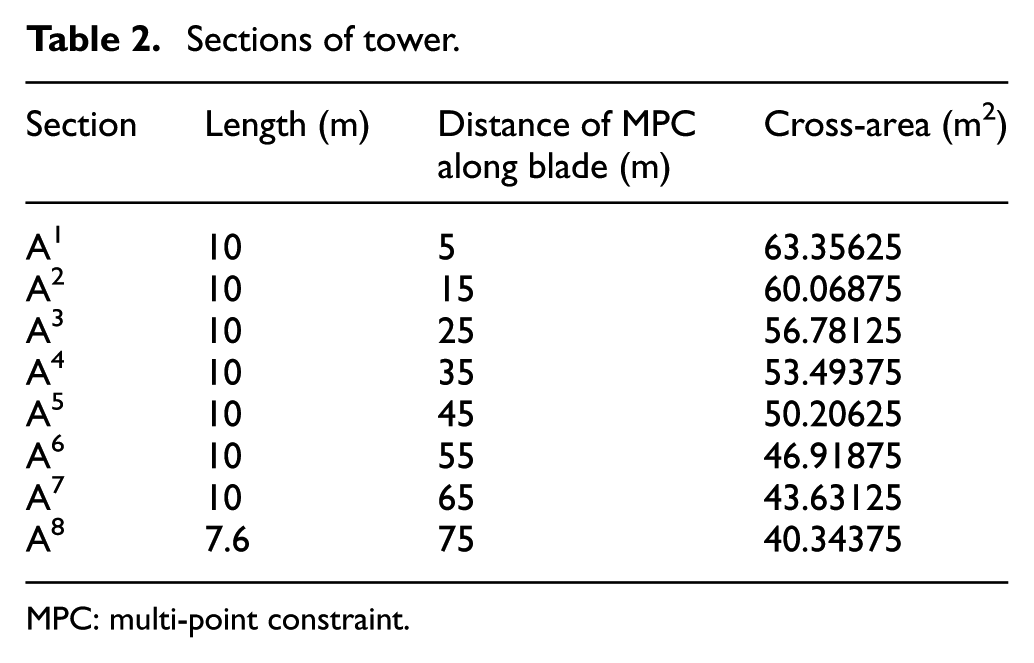
MPC: multi-point constraint.
The flexible components are analyzed with the normal mode solution type in NASTRAN. Since the bending is the most objective mode shape, the analysis is conducted with the fixed-free boundary condition during the simulation. Finally, there are total 29 forces acting on the flexible components. The external wind loads applied in ADAMS is shown in Figure 4.

Flexible tower and blades in ADAMS.
Spar platform
The spar is divided into 13 sections from the bottom, as shown in Figure 5. The length of each section is 10 m, and the origin of the spar coordinate locates in the contact surface of sections 12 and 13, which is 10 m below the top of the spar.

Spar platform in ADAMS.
Modeling of external loads
Both the wind and wave loads are time and position dependent. These loads are approximately expressed using mathematic equations and divided into sections by the FEM. Finally, these loads are summed up according to the strip theory.
Loads on superstructure
Speed of wind
According to the rated power of 5-MW offshore wind turbine, the wind speed is around 11.2 m/s. Real-time monitoring data of the wind speed are adopted from a meteorological observation station that is 10 m above the SWL. According to Journèe and Massie, 22 the wind speed of every height can be obtained through equation (1)

where Zj represents the height of measuring points, which are the time- and position-dependent values with respect to the SWL. Zr represents the height of the standard measuring point that is 10 m above the SWL. Vj represents wind speeds of each measure point and Vr represents the standard wind speed, which is measured at standard measuring point.
Wind loads
Drag equation is a practical formula for the case that an object moves within a fully enclosed fluid. In real case, the wind loads are distributed on the entire surface of the wind turbine. In here, seven concentrated forces are applied for each blade and eight for the tower to express the wind loads. Finally, Fw sums up all the wind loads acting on each component as shown in equation (2). The number n is 7 for the blade and 8 for the tower

where ρ, CD, and Vj represent the density of air, the drag coefficient, and the speed of wind of the jth section, respectively. Aj represents the cross-area of the jth section, which is judged according to the real shape of the blade and tower. The cross-area of each section for the blade and tower is given in Tables 1 and 2, respectively.
Loads on substructure
Sea state
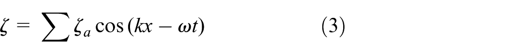
Based on the linear wave theory, the elevation of the surface wave is functions of time and position as expressed in
With the assumption of the water depth being 200 m, 23 the velocities and accelerations of the water particles can be calculated from equations (4) and (5), respectively

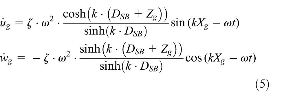
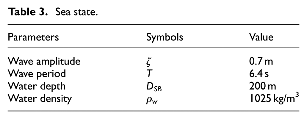
where the wave number k and wave angular velocity ω are defined as equation (6). Table 3 shows the sea state

Sea state.
Buoyancy
Because the center of mass (CM) of the spar platform is lower than the center of buoyancy (CB), restoring forces and moments are generated automatically according to qi, the DOFs of the platform. The geometry of the spar is created according to NREL and is listed in Table 4.
Properties of spar.

CM: center of mass.
In view of the continually changing of the CB and the column shape of the platform, the buoyancy is expressed as equation (7). The weight of the system should also be added during the simulation

The first term represents the buoyancy of the system at the initial position, which is equal to the weight of the displaced fluid. The vector

Hydrodynamic loads
The horizontal hydrodynamic drag force is a quadratic function of the relative velocity of the fluid with respect to the platform, as shown in equation (9).

The hydrodynamic loads, induced by the propagating wave in the vertical direction, are indicated with superscript 3 as shown in

Added mass and Froude–Krylov effect
The added-mass effect comes from the relative acceleration of the spar with respect to the surrounding fluid, and the Froude–Krylov force represents the pressure effects of the undisturbed incident waves as shown in

where CA is the coefficient of the added-mass normal to the spar, and Bj denotes the volume of the jth section that is counted if the geometric center of the said section is below the wave height.
Mooring loads
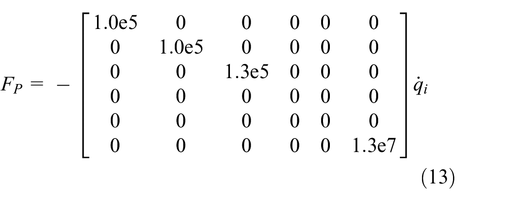
The external loads force the spar platform moving away from the equilibrium position. The mooring system constrains this motion within an approved range. The linearized mooring loads are functions of DOFs qi, as shown in equation (12). The stiffness matrix is judged according to the physical properties of mooring cables and the layout types. The damping and inertia of the mooring system are neglected in this equation

The first part represents the weight of mooring system in undisplaced position, while the second component represents the restoring forces and moments generated by the changing of the spar platform.
Additional damping
Additional damping is needed for the motions of OC3-Hywind system. The damping forces are linear function of qi, the first time derivation of DOFs qi. The damping matrix is defined according to Gudmestad 24
Because both the velocity and acceleration of the water particles change with the water depths, the spar is divided into 13 sections with respect to the axial length. The velocity and acceleration at the middle point of a section are used to express the hydrodynamic loads and the added-mass effect of the said section. The external forces, including the hydrodynamic force, and effect of the added mass and Froude–Krylov are concentrated on the geometric center of each section. The buoyancy, the additional damping forces, and the loads from mooring cable system are acting on the origin of the spar platform. Finally, according to the strip theory, forces acting on each sections are summed up with respect to the global frame, as shown in Figure 6.
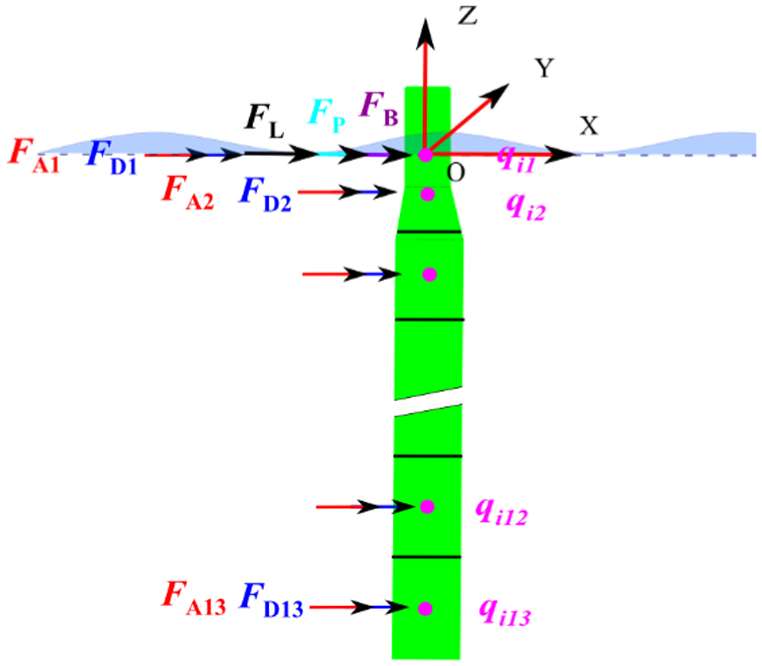
Loads acting on the spar platform.
Dynamic simulation and analysis
The influence of the flexible deformation is investigated by comparing the global motions of the wind turbine from the flexible body modeling with those from the rigid body modeling. The relationships between global motions of the wind turbine and external loads are studied based on the flexible body modeling. The measuring point locates on the center of the rotor.
Flexible deformation
Simulation results from the rigid body modeling are identified with red circles, while the blue ones for the flexible body modeling. The flexible deformation almost has no effect on the heave motion as illustrated in Figure 7. The spar platform moves around the SWL with a range of 1 m at the said sea state. The amplitude of the surge motion increases 11.1% by the flexible body modeling compared to that by the rigid body modeling, as shown in Figure 8, and the displacement of nacelle is about 5 m away from the initial position when the speed of wind is around 11.2 m/s. The flexible deformation influences the amplitude of oscillation instead of the frequency. The oscillating region of pitch in rigid body modeling is smaller than that in flexible body modeling when the measuring point locates at the center of rotor as illustrated in Figure 9. However, it is larger in rigid body modeling than that in flexible body modeling when the measuring point locates on the origin of the spar coordinate, which is shown in Figure 10. This indicates that the flexible deformation of the tower shares the bending moment coming from the rotor. Due to the flexibility of the tower, the oscillating region of pitch increases 13.8% compared with that in rigid body modeling at the rotor. The pitch motion ranges from −0.5° to 2.5° at the nacelle.

Comparison of heave motion.

Comparison of surge motion.

Comparison of pitch motion.

Comparison of pitch motion at the origin of the spar platform.
Load–displacement relationships
The relationship between the external loads and the motions of the spar platform is important, especially for the optimal design. The motions of the spar are induced by external loads, and the external loads are related to the geometric configuration. The ideal motions of the wind turbine can be achieved by modifying the geometric configuration if the load–displacement relationships are clear.
Figure 11 shows the relationships among the motion of pitch, hydrodynamic, and speed of wind at the center of the rotor. The hydrodynamic loads have large effect on the motion of pitch during the normal operation. The frequency of the pitch depends on the frequency of the propagating wave. The mean value of the pitch angle is around 1° instead of 0° due to the effect of the wind loads.

The relationship among pitch, hydrodynamic, and wind speed.
Figure 12 shows the relationships among the motion of surge, hydrodynamic, and speed of wind at the center of the rotor. The results illustrate that the wind loads, instead of the hydrodynamic loads, have dominant influence on the general tendency of the surge. The oscillation of the surge is generated by the hydrodynamic loads.

The relationship among surge, hydrodynamic, and wind speed.
Figure 13 shows the relationships between the motion of surge and X-directional mooring loads. Since the mooring system is applied to limit the transformation of the platform in the horizontal direction, the mooring loads are generated automatically depending on the displacement of the platform. This figure indicates that the mooring loads change proportional to the motion of surge. The hysteresis is not obvious due to the linear expression of the mooring loads; the tension within cable has hysteresis for transmission in real case.

The relationship between the motion of surge and mooring loads.
Conclusion
A 5-MW offshore wind turbine installed on a floating spar platform was modeled with a hybrid method of finite element MBS using ADAMS, PATRAN, and NASTRAN.
The effect of the flexible deformation on the global motion of the wind turbine was investigated by comparing simulation results from the flexible body modeling with those from the rigid body modeling.
The flexible deformation enlarged the motions of surge and pitch by 11.1% and 13.8%, respectively, and had slight influence on the heave motion.
The ranges of motions were illustrated according to the simulation results achieved with the defined wind and wave conditions in this article.
The relationships between the external loads and the global motions of the spar were studied. The optimal design can be conducted according to the load–displacement relationship.
Combining the research results of the reduced modeling in which the flexible deformation is ignored, the research results of this article are valuable references for the design of the offshore wind turbine installed on a floating spar platform.
Footnotes
Academic Editor: Fen Wu
Declaration of conflicting interests
The author(s) declared no potential conflicts of interest with respect to the research, authorship, and/or publication of this article.
Funding
The author(s) disclosed receipt of the following financial support for the research, authorship, and/or publication of this article: This work was supported by Human Resources Development Program of Korea Institute of Energy Technology Evaluation and Planning (KETEP), Ministry of Trade, Industry and Energy of Korea (Grant No. 20134030200290).