
Abstract
Floating offshore wind is an emerging technology that holds considerable potential to utilise areas deeper than 60 m for sustainable energy generation. As the floating offshore wind turbine industry continues to develop and grow, the capabilities of established port facilities need to be assessed as to their ability to support the expanding construction and installation requirements. This article assesses current infrastructure requirements and projected changes to port facilities that may be required to support the floating offshore wind industry. Understanding the infrastructure needs will help to identify the port-related requirements. Floating offshore wind turbines can be installed further out to sea and in deeper waters than traditional fixed offshore wind arrays, meaning they can take advantage of stronger winds and additional sea locations. Separate ports are required for substructure construction and fit-out of the turbines and maintenance. Large areas are required, about twice the plan area of the structure, for the laydown of mooring equipment, inter array cables, turbine blades and nacelles. The capabilities of established port facilities to support floating wind farms can be assessed by evaluation of size of substructures, height of wind turbine with regards to the cranes for fitting of blades, distance to offshore site and offshore installation vessel characteristics. Spar, barge, TLP and semisubmersible types have been deployed as demonstration units. Pre commercial units have been installed off the coasts of Portugal and the east coast of Scotland. This article reviews and defines the port and shipyard requirements for floating offshore wind turbines. It will support decision-makers to guide port infrastructure investments and project developers in their site selections. There up to 15 port functions that need to be considered, for construction, assembly and support of offshore activities. These could be fulfilled by one or a combination of different ports.
Introduction
Future global floating wind is projected to reach 54 gigawatts for projects, by 2030, from an early stage of development through to those which are fully operational. 1
The ability to assemble Floating offshore wind turbines (FOWT) structures on or near shore means minimising highly weather dependent operations such as offshore heavy lifts and assembly, saving time and costs and reducing safety risks for offshore workers. Maintenance might take place in safer nearshore conditions for barges and semi submersibles.
Offshore renewables, such as floating wind, can build on the experience, of oil and gas offshore construction experience as well as the fabrication work on fixed bottom wind farms.
The floating offshore wind industry is in the early stages of development and port facilities are required for substructure fabrication, turbine manufacture, turbine construction and maintenance support. The article discusses the potential floating wind substructures. Demonstration and pre commercial units have been installed. With regards to ports the primary focus will be on commercial-scale (30+units) device floating wind energy farms.
The function of ports for the construction, installation and maintenance of floating wind is varied:
Supply base for the geotechnical and weather survey of the offshore site. This takes place before the detailed design of the FOWT starts.
Construction of the substructure, possibly an existing shipyard
Quayside factory for blade manufacture
Loadout quay for nacelle and tower
Laydown area for mooring components
Laydown area for dynamic array cables
Fit-out quay for installing turbines
Support port during offshore installation phase
Future maintenance support harbour
This paper reviews the port requirements and defines the role of ports for floating wind.
The challenges for floating offshore wind (FOWT) depend on the type of substructure, water depth, prevailing weather conditions, seabed soil and size of the wind turbine. To date the largest turbine on a FOWT is 9.6 MW.
The remainder of the article is structured as follows: Section 2, provides a brief literature review for floating wind construction and installation. Options for reviewing floating wind construction ports are discussed in section 3. The analysis of port requirements are considered in section 4. Results are shown in section 5. Discussion is in section 6 and conclusions are given in section 7.
Literature review
The shipyard for substructure construction can be a long distance from the offshore location. But the fit out yard needs to be as close to the offshore site as possible, to minimise tow out times which are weather restricted. Ports are regarded as the pinch points in the deployment of floating offshore wind turbines. 2 The availability of fit out ports, and respective water depth alongside the quay, is a major factor in determining the type of floating wind turbine that is to be used. This is important as the design focus for floating wind platforms is often on the site conditions. Yet, ports are a critical engineering constraint to be able to realise the installation of floating turbines. The achievement of energy production decarbonisation goals requires stepping up the deployment of floating offshore wind. Upscaling port infrastructure and investments need to be aligned with the long-term use of FOWT. 3
There are several floating wind designs competing for commercial deployment, which will need different infrastructure requirements. The assembly of floating wind systems, as opposed to bottom-fixed turbines, is mostly based onshore. Therefore, ports will need expansion of their land area, quay reinforcement, storage for components, carrying capacity, cranes and other retrofits to host mass production of floaters and other turbine components.
The floating wind industry could partly use the infrastructure of the existing ports, currently used for bottom-fixed offshore wind and offshore oil and gas platforms. Ports, existing or future, need to maximise the whole supply chain efficiency of existing bottom-fixed offshore wind platforms. Space is and will become a bigger issue for ports. To overcome this, ports will require new strategies and regional collaboration. Additional port facilities are needed to support wind turbine manufacturing, substructure fabrication, fit out, and support for offshore installation, operation and maintenance of wind farms.
Demonstration scale projects (approximately less than five devices) have different port infrastructure requirements than full commercial scale projects (30+ units), as the supply chain logistics and costs of scale will be significantly different. 4
Floating wind status
General
The main parts of a floating offshore wind turbine are shown in Figure 1(a). The topsides are the blades, nacelle and tower, which are provided by the turbine manufacturer. The substructure is in part limited by the port used for construction and fit out. The moorings include the mooring lines and the anchor type, for example, drag anchors, suction piles, driven piles or drilled piles.
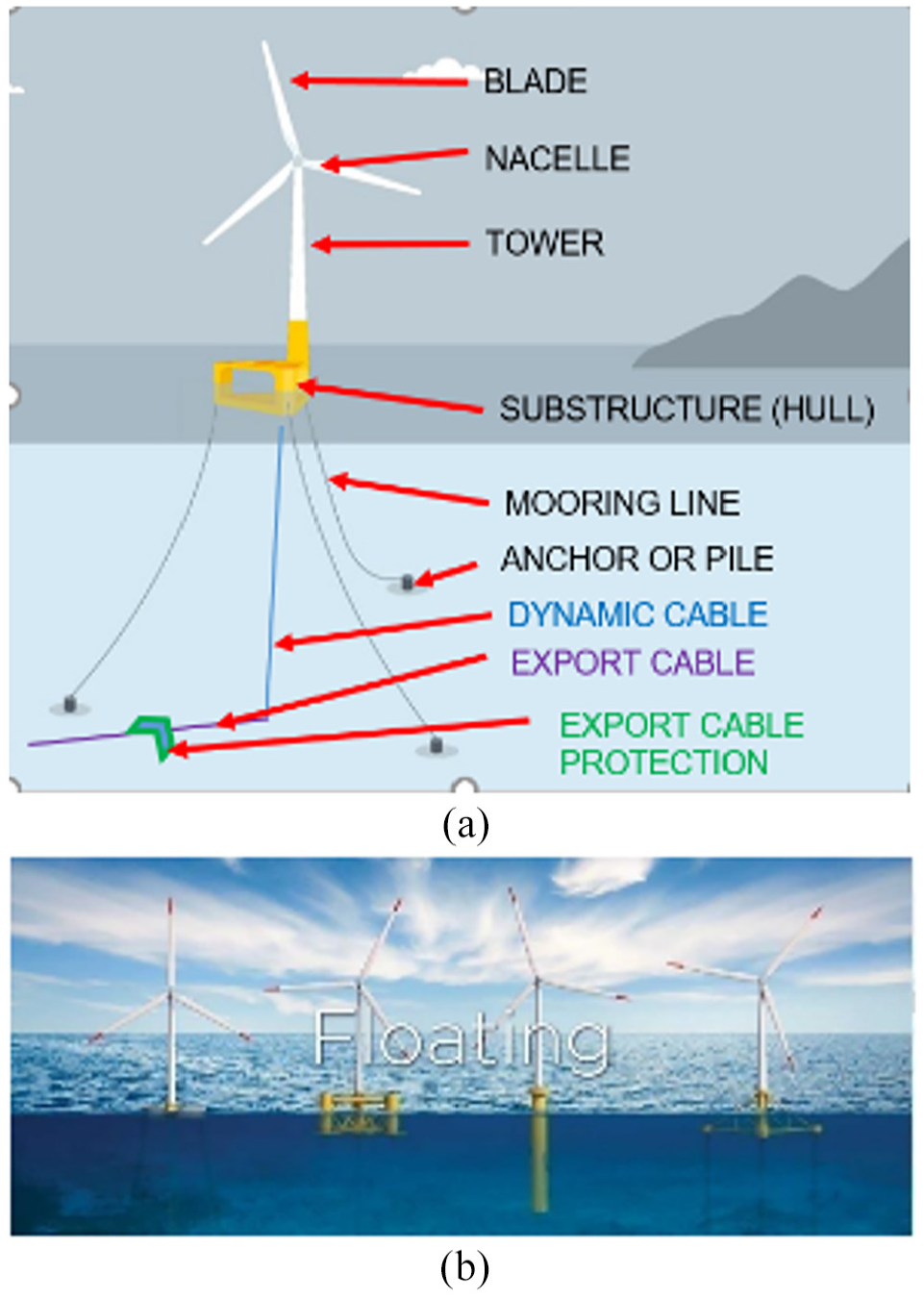
(a) Main parts of FOWT 5 and (b) floating wind types
There are dynamic cables from the substructure to the seabed. The export cable is buried in the seabed. The export cable may go to land based grid, typically via a substation or to supply electricity to offshore oil and gas platforms.
The different types of floating offshore wind turbines are given in Table 1. The minimum water depth for alongside quay construction work is at lowest astronomical tide (LAT) 1m under keel clearance plus the level trim draft of the FOWT. Ports with a water depth of up to 15m can accommodate Semi-submersible, Barge and TLP type platforms, whilst Spar platforms require up to 80m water depths.
FOWT types and fit out quay draft range requirements.
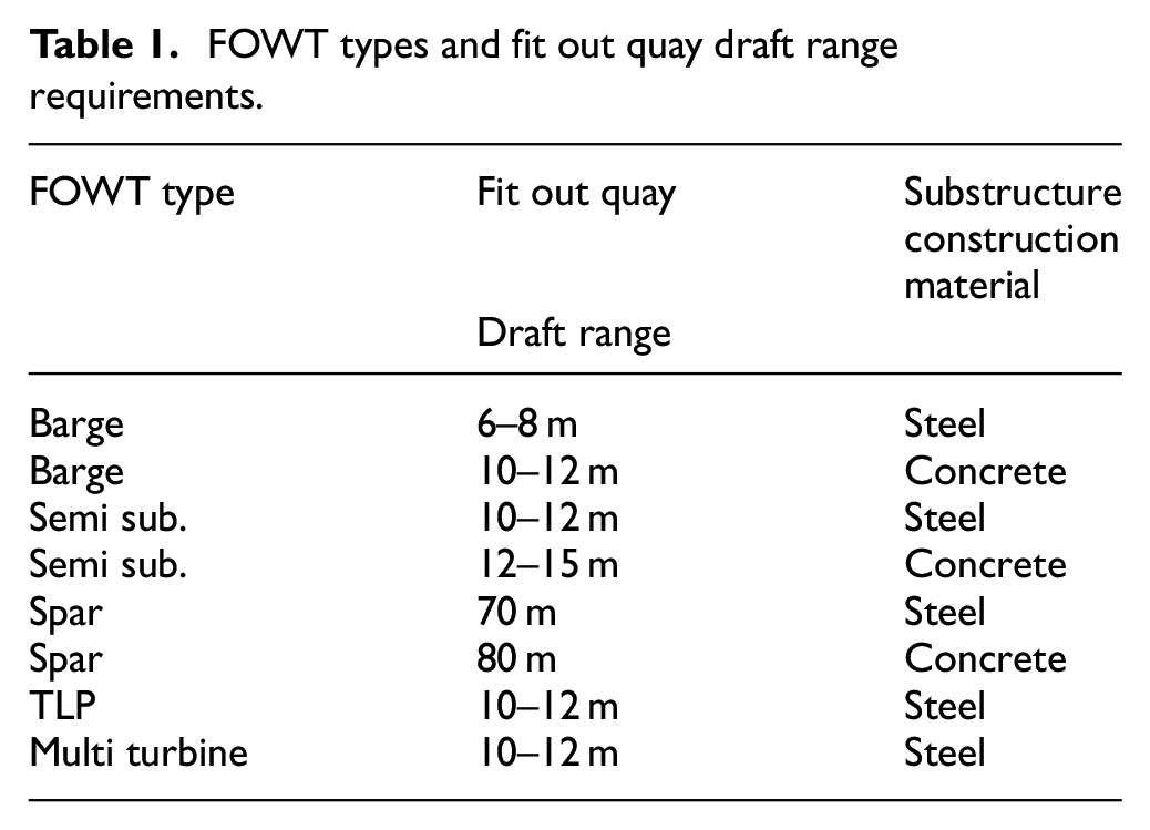
Concrete structures, for the same plan dimensions, have a higher weight that steel substructures and so the concrete structures have a deeper draft.
Spars both steel and concrete have very deep drafts and gain their intact stability from adding solid ballast to their base.
Barges gain their stability from their width and they have the minimum draft, however they have the largest motions in operation.
Semi submersibles gain their stability from the second moment of water plane area and have lower motions than barges, Multi turbine FOWT are based on very large semi submersible hulls.
The floating offshore wind turbine main types are as shown in Figure 1(b). To date there are the following types in operation:
Steel semisubmersible
Steel barge
Steel spar
Concrete barge
There are several options currently under discussion for Tension Leg Platform (TLP) installation:
Fit temporary buoyancy in the shipyard and remove after offshore installation
Build piece small offshore using a crane vessel with active heave compensation in the main hook
At the tow out draft have a large water plane area and after initial mooring tensioning add water ballast, so that at the installed draft there is a small water plane area
Barges
A barge is a hull made of either steel or concrete, see Figure 2. The assembly of the structure is performed onshore and towed offshore using tugs. Barge structures have a low draft, making them suitable also for shallow water ports, though they have higher motions in waves than other types of FOWT. Some barges are anchored to the seabed using catenary mooring lines whilst one type uses weather vaning technology. Currently structures weigh around 2000 tonnes (steel) and 4000 tonnes (concrete).
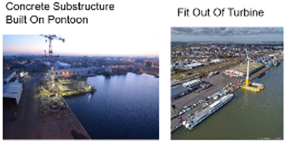
Concrete barge. 6
Semi submersibles
A semi-submersible substructure is a hull with columns which are connected to each other with bracings. The structure is anchored to the seabed using catenary or taut mooring lines. This substructure is assembled onshore and, despite its heavy weight, it has a relatively low draft of approximately 10 m during transportation. The weight of the structure for a single structure is around 2500 tonnes to 5000 tonnes. Most current designs have the turbine either in one corner or one side to maximise use of onshore crane capacity.
Other semi submersible substructures concepts have multi turbines in a single platform. These structures are moored using a weather vaning system.
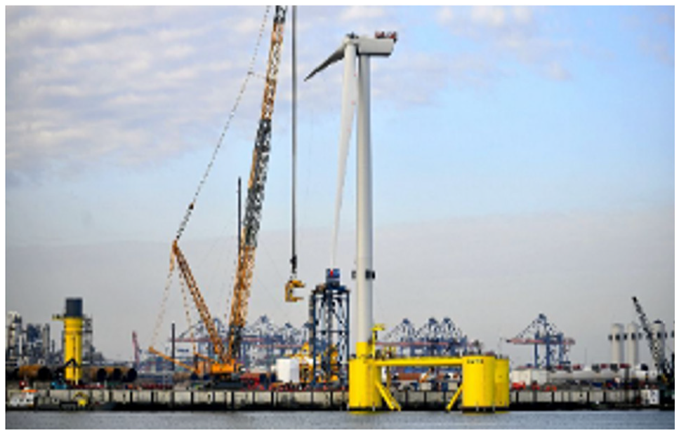
Figure 3 shows a loadout from land onto a heavy transport vessel. The construction of a semisubmersible in a drydock is pictured in Figure 4. For a floatout from a drydock temporary buoyancy may be required to minimise draft and to have zero trim and heel.
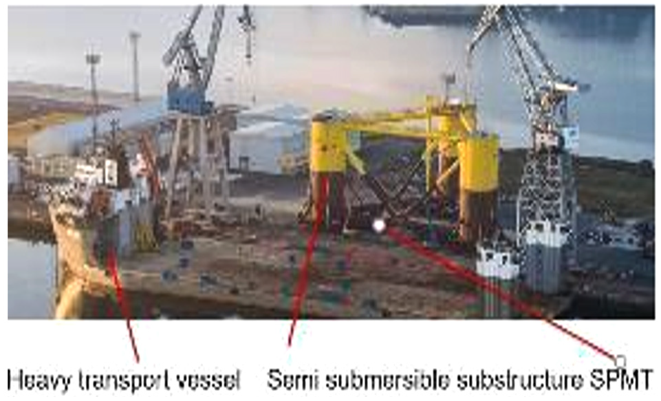
Semi sub. loadout from land. 7
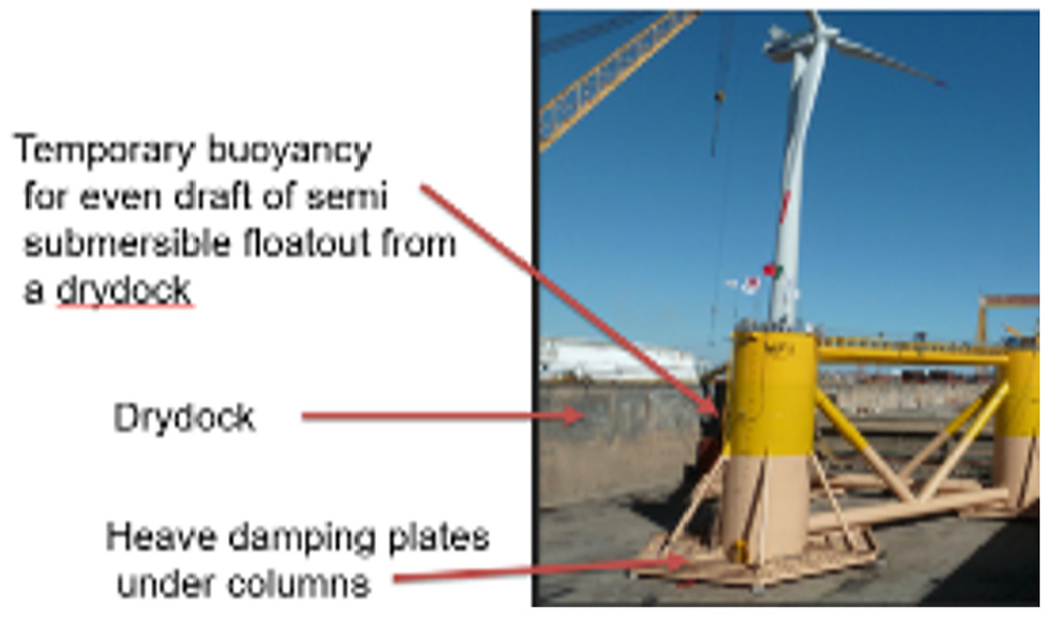
Semisubmersible in drydock. 8
SPARs
A spar-buoy (or spar) is a cylinder structure. It is stabilised by keeping the centre of gravity below the centre of buoyancy, using a ballast made of one or more heavy materials. This is the structure with the largest draft, between 70 and 90 m once installed, minimising the motions and stabilising the structure. However, this can translate into more complex logistics in the assembly, transportation and installation of the foundation.
The assembly of the steel substructure is performed onshore by building the Spar hull horizontally. The steel weight of one structure is around 2500 tonnes to 5000 tonnes before ballasted. The substructure is loaded out onto a heavy transport vessel (HTV), taken to a sheltered location for float off, see Figure 5. The Spar hull is then upended using water ballast, in deep sheltered water. Then solid ballast is added to the base. The topside turbine (tower, nacelle and blades) is assembled on land and fitted onto the Spar hull, in sheltered water using a semi-submersible crane vessel (SSCV), Figure 6.
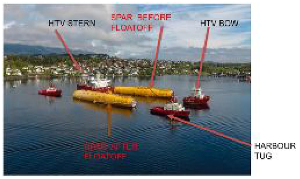
Spar floatoff before upending. 6
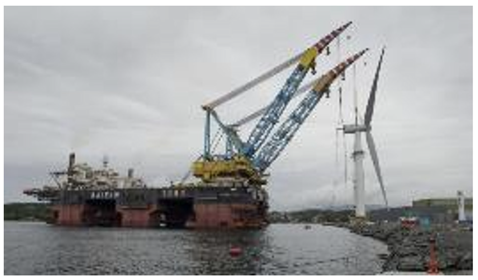
Spar topsides lift off from topside quay.
The concrete spar starts off by being slip formed vertically in a dry dock. The completion of the substructure continues in deep water using slip forming. Solid ballast is added to the base.
Both steel and concrete types of Spar require temporary moorings to be set up in sheltered water and also work barges to be alongside.
TLPs
The tension leg platform (TLP) has low or negative intact stability and thus unique methods of installation are required.
Offshore turbines
Turbine blade lengths and nacelle diameters are typical manufacturer’s information. Table 2 gives offshore turbine dimensions and weights of the nacelle for different power outputs. Existing pre commercial floating wind turbines are 8–9.6 MW.
Turbine dimensions and weights.
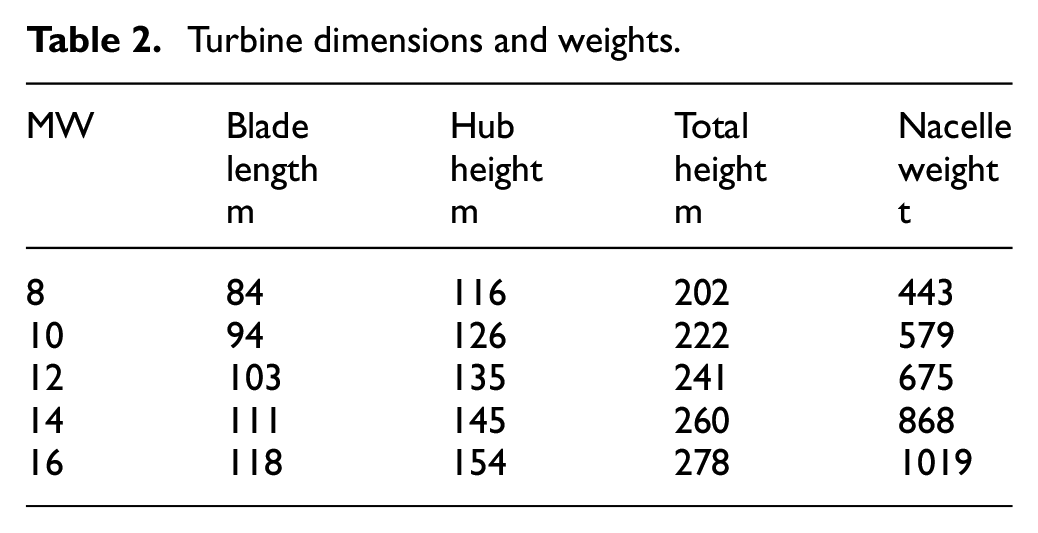
The hub height at which the nacelle has to be installed is a limiting factor for available onshore cranes and for existing floating crane vessels.
Methods of reviewing ports
Substructure
The substructure can be built as follows:
In a drydock: This is applicable to barge types and medium sized semi submersibles.
On land: This is possible for barges, semi submersibles and Spars.
There are further practical constraints, such as gaps between orders, meaning that employers are not able to retain all the skilled labour hired for a job. Each new job must therefore carry some cost of hiring and allow time for a certain amount of learning on the first units produced, causing process inefficiencies something which is minimised where the same teams are working continuously from one project to the next.
Installation vessels are continuing to increase in size, which is further increasing the available water depth limits for quayside load-outs. Some sites have short windows during high tide to complete load-outs, increasing the loadout time and cost.
Blade manufacture
Because of the length of the turbine blades, (see Table 2) they need to be manufactured close to a loadout quay as they are too long to be transported on public roads. They may be loaded by crane, either individually as shown in Figure 7, or in bundles of three onto a transport vessel, for passage to the fit out quay.
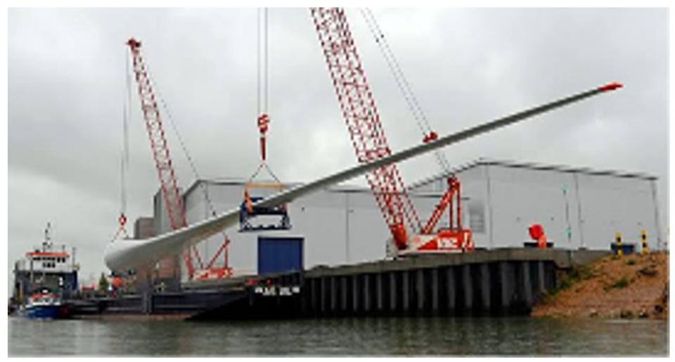
Blade loadout from quay.17
Ports will continue to increase the use of roll-on/roll-off (RO-RO) vessels particularly for transporting large components (i.e. nacelle, blades). This reduces time and logistical costs compared with traditional methods for component delivery [four of lift-on and lift-off].
Loadout quay for mooring equipment
The mooring system needs to be installed prior to the offshore arrival of the completed floating offshore wind turbine. The mooring lines and anchors will be delivered from their respective construction ports to a mobilisation port close to the offshore location.
Mooring and anchor systems can be stored in a separate port and do not need particularly high lifting capability. There is potential to use drums to store synthetic rope, which would require less space.
Loadout quay for subsea cables
Subsea cables need to be stored onshore prior to deployment offshore. The cables are usually installed prior to the installation of the floating offshore wind turbine. There are export cables which are buried in the seabed and dynamic array cables which connect the export cables to the FOWT.
The export cables may be built and loaded out a long way from the final location as they require specialising manufacturing facilities. The multiple dynamic array cables can also be built a long way from the offshore location, so a marshalling port may be required for the cables.
A secondary port may be required for concrete protection mat construction and storage, these mats being used to protect the export cable from damage,
Loadout quay for nacelle and towers
For smaller wind turbines the tower and nacelle may be built away from a loadout quay. However with the expectation that the minimum size of commercial floating offshore wind turbines is 8MW, with the likelihood that the wind turbines will be at least 10MW capacity on floating offshore wind turbine the nacelle and tower will be too big to be transported on public roads.
Fit out quay
A fit out port will need access to a large laydown area to store nacelles, blades, towers.
For turbine assembly, a port will need to have cranes capable of lifting the nacelle, the heaviest and highest lifting operation and is thus one of the limiting factors, for crane hire. Figure 8 shows a 9.6 MW blade being lifted by a large onshore crane.
Blade lifting onto semi sub. 5
Wet storage
Substructures need to be wet stored prior to fitting the turbine topsides. This requires the laying of temporary moorings.
Navigation out of fit out yard
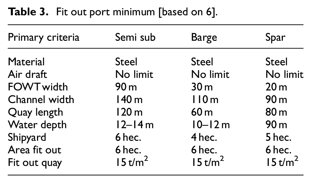
Navigation and fit out port requirements are summarised in Table 3.
Fit out port minimum [based on 6].
Results
Applying the review criteria for each phase a range of constraints and practical requirements regarding weather restrictions, and required port areas have been established
Weather restrictions
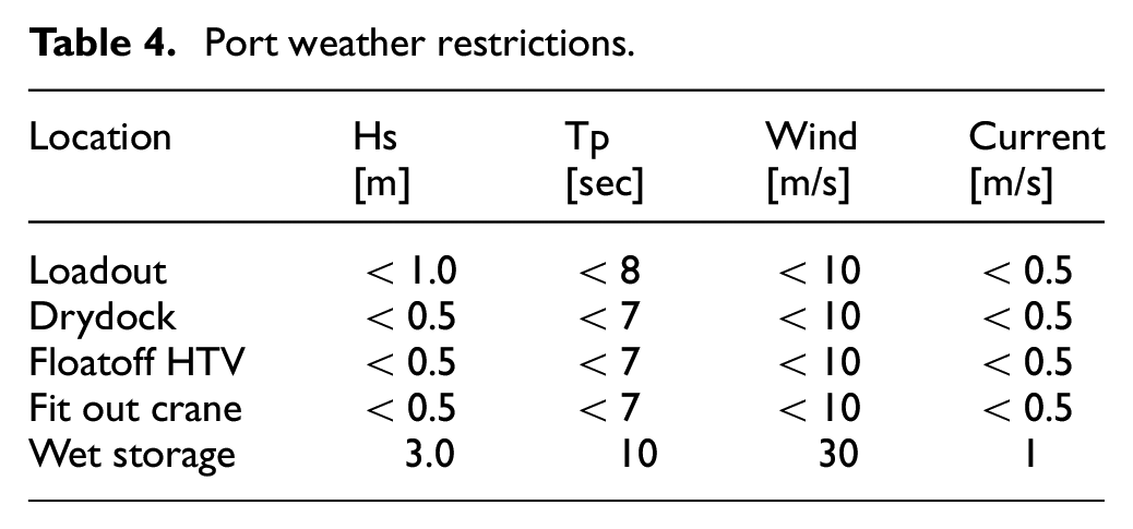
The weather restrictions are expected to be as follows for the port activities, Table 4.
Port weather restrictions.
Port areas
The approximate port area requirements for the different factors are shown in Table 5. Port area directly depends on:
Port area estimates.
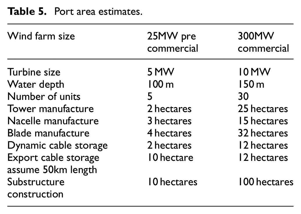
Type of FOWT
Size of turbine
Number of turbines in the wind farm
The number of turbines to be installed in one summer season
Table 6 shows the typical port areas required for different types of moorings. Specialised equipment will need to be stored on land and to be loaded onto installation vessels, for example, work class ROVs, hammers for driven piles, drilling equipment for drilled piles or subsea pumps for suction piles
Mooring port laydown areas.
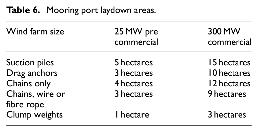
The moorings have the following marine activities:
Anchor loadout by crane onto cargo ship
Offload anchor by crane from cargo ship onto mooring storage quay
Mooring line loadout by crane onto cargo ship
Offload mooring line by crane from cargo ship onto mooring storage quay
Load assembled mooring line onto mooring installation vessel
It can be expected that as larger turbines are deployed on fixed bottom offshore wind turbines that 15 MW wind turbines will be deployed on floating offshore wind turbines.
Cable manufacture is carried in specialised factories close to their own loadout quay.
Ports for steel and concrete substructure
Steel substructures have the following advantages, in shipyard construction 9 :
Established in the offshore wind industry:
Assembly can be execute relatively fast if components are pre-fabricated
Lighter substructures are possible (compared with concrete) which minimises water depth requirements at shipyard, dry dock and the fit out port
Concrete substructures have the following advantages in construction ports:
Concrete supply adaptable to local conditions and project requirements
Local content is ensured (local workforce, local supply chain)
No specialised equipment, such as large scale welding machines, required
Low costs of concrete as a raw material
Visual impact during construction
There is high visual impact from floating wind turbine during manufacturing, assembly, repair (near shore or in port) and decommissioning, Figure 9 and Table 2. However, it is expected to encounter low opposition as these are short-period tasks that will bring jobs to the fit out port area. 11 There must be no overhead obstructions, bridges or power cables, between the fit out port and the offshore site.
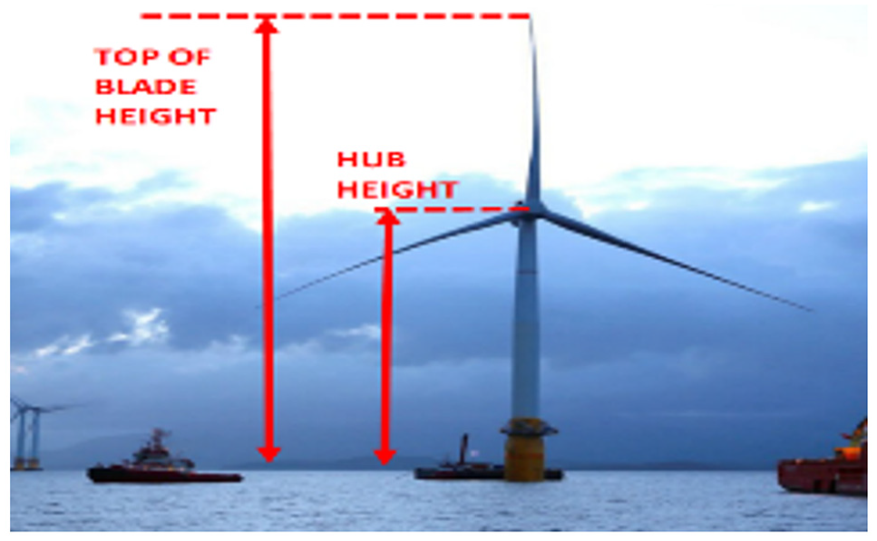
Top of blade height, Hub height.
Discussion
The market for floating platforms is still in its infancy. There are many platform types, and only few have been demonstrated pre-commercially. Existing shipyards and fit out quays have been used. Different manufacturing techniques will require different facilities, from large yards to covered premises to dry docks. 11 Floating offshore structures are large and will need storage and/or transfer to assembly facilities. It is likely that wet storage will be used, so ports able to offer sheltered moorings ahead of turbine integration will have an advantage. Storage and assembly may happen at different port locations and could be done at quayside (with onshore cranes) or in sheltered locations using floating assembly bases or floating cranes.
Industrialisation of floating wind technology is the key for future cost reductions. Ports form an important element in the commercialisation of floating wind and should actively plan for these requirements.
Port facility requirement criteria will differ for each port classification and substructure technology as the functions and installation vessel requirements are different. Because the industry is at an early stage, and deployment technologies and methodologies are still in development, the requirements presented are intended only as a broad review of likely port facility requirements based on available data and technology.
Key outcomes from the study include the following for semi submersible floating offshore wind turbine construction:
Quayside capacity requirements are greater than for typical cargo, up to 20 tonnes/m2.
A protected harbour with significant staging area is needed for final fit out throughput.
Floating wind substructures will likely be wider (more than 60 m) than most cargo vessels, and require deep draft channels. Channel width may need to be over 100 and 150 m depending on specific technology. Channel depth may need to be greater than 12 m depending on specific technology and temporary floatation units.
For tow-out of an assembled unit there must be no air draft restriction between the assembly site and the final installation site.
Rail and road connections will likely be required for transport of materials
Steel barge requirements are similar. Spars are similar but need deep sheltered water close to the shore. TLPs requirements are unknown at present.
An artist’s impression for FOWT port requirements, at Port Talbot, is shown in Figure 10. It shows the additional space for fabrication, assembly and loadout, as well as the area for wet storage and tow-out.
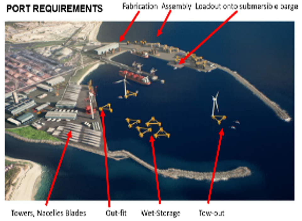
Artists impression of FOWT port. 10
Table 7 summarises typical material requirements for a steel semi submersible FOWT.
Typical material quantities. 13
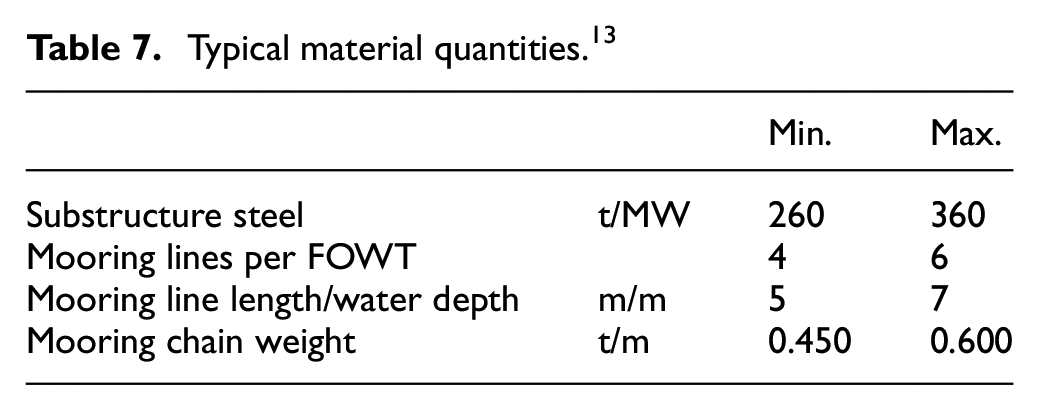
For a steel barge up to 12 mooring lines are required. For a Spar, both steel and concrete, large quantities of solid ballast are also required.
New large-scale floating offshore wind ports and factories are to be built in the UK with government investment of £160 million. 12 The deep waters off the Scottish coast offers huge opportunities, building on the floating offshore wind farms off the coast of Aberdeen. The Celtic Sea is also a major development opportunity for the offshore wind sector, with a combination of deep waters and strong winds, and which is set to create significant opportunities for development in Wales.
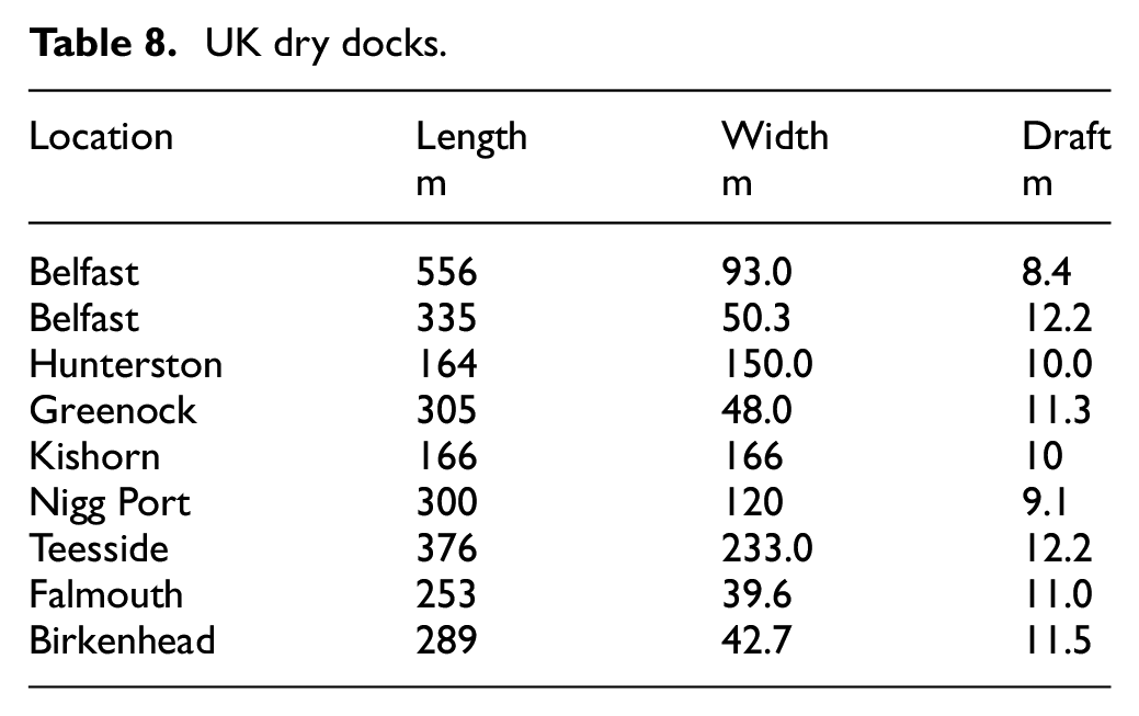
There are existing dry docks, some not in use which could be used for FOWT construction as shown in Table 8. These dry docks have access to the open sea without restriction of overhead cables or bridges. These ports may also be suitable for topside fit out.
UK dry docks.
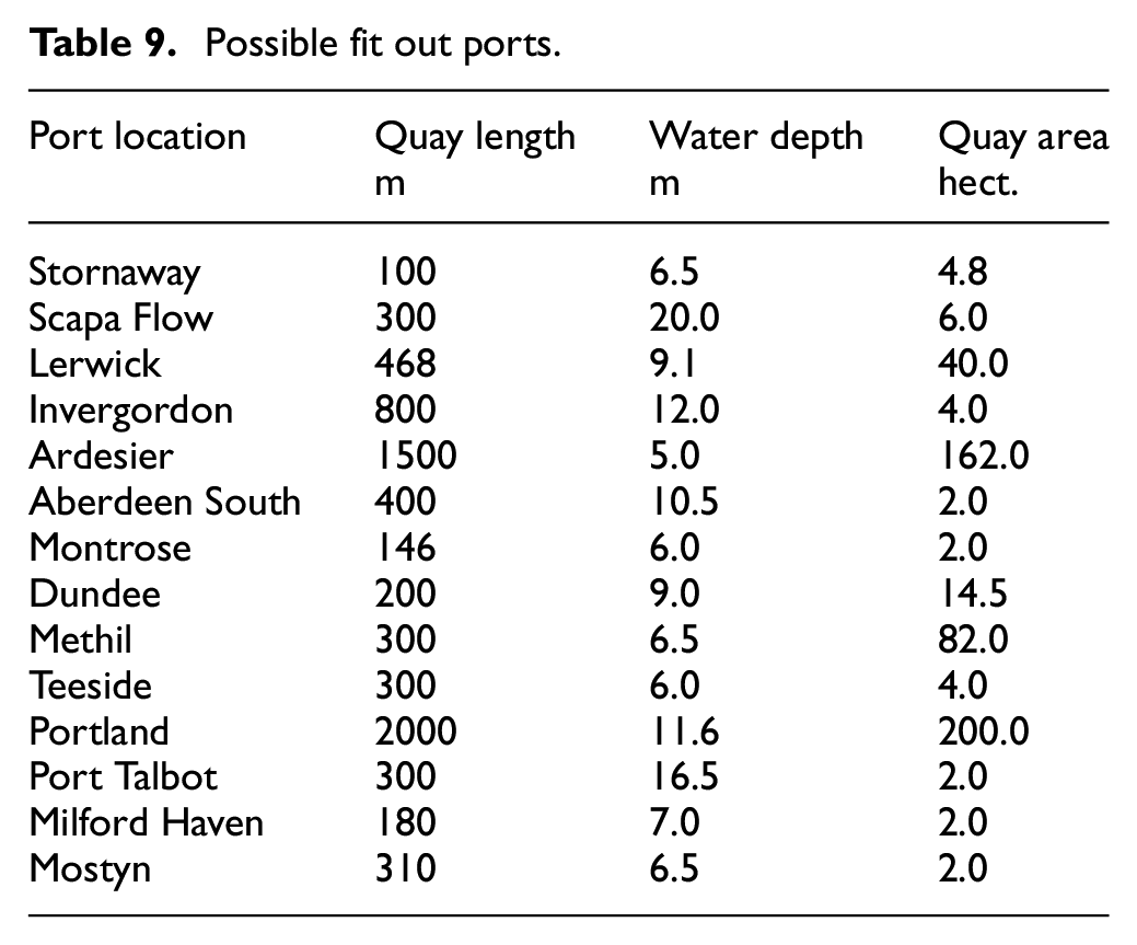
Various addition ports around UK have port facilities that might be used for fit out and have open access to the sea, Table 9. Water depth is at extreme low tide and in some locations may be improved by dredging.
Possible fit out ports.
To construct and fit out floating offshore wind turbines may require dredging at the quay edge and strengthening of the quay.
Ports are used to deliver the following to the fit-out port:
Substructure
Topside tower
Nacelle
Blades
Loadout ports are required for the delivery of mooring equipment to the mooring assembly port:
Anchor (or suction pile, driven pile or drilled pile)
Chain and clump weights
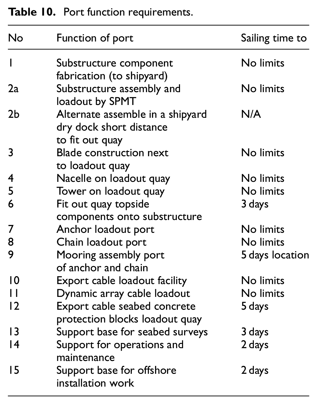
The topside is the tower, the nacelle and the blades. Table 10 summarises estimated maximum feasible port sailing times to the offshore location and functions. There up to 15 port functions that need to be considered. These could be fulfilled by one or a combination of different ports. Table 10 represents the port requirements for steel semi submersibles and barges. Concrete semi submersibles and barges are similar to the steel substructures except that deeper water depths are required at the fit out quays.
Port function requirements.
For a steel Spar the variation of item 6, in Table 10 is as follows and requires an additional port for loadout of solid ballast, so the mooring, cables and topside ports are the same as the semi submersible ports:
The substructure is built horizontally in a shipyard and loaded out onto a Heavy Transport Vessel (HTV).
The substructure hull is floated off the HTV, close to sheltered deep water (more than 80m depth)
The substructure is upended
Solid ballasting ship loads iron ore, from a loadout quay
The substructure has solid ballast added to the base from the solid ballasting ship
The topsides is completed onshore
The completed topside is lifted off the quay, by a large semi submersible crane vessel (SSCV)
The SSCV lifts the topsides onto the top of the substructure.
Support for the inshore installation is form the quay used to prepare the topsides
Concrete Spars are partially built vertically is a dry dock and are completed in sheltered deep water by skip forming The remaining port requirements are as per steel spars.
For TLPs port requirements are similar to those required for a semi submersible, except for the option where the structure is built piece small offshore.
Conclusions
Ports are required to facilitate the assembly, installation and operations of Floating Offshore Wind Turbines (FOWT). For commercial projects with multiple turbines, shipyards need to be able to construct several FOWT at one time. Similarly fit out quays need to be able several FOWTs at the same time.
For substructure dry ocean transport there are no limits on shipyard locations. However the shipyard requires a quay strong enough for self propelled modular transporters (SPMTS) to have a side loadout onto a Heavy Transport Vessel. There must also be sufficient water depth for the Heavy Transport Vessel to stay afloat at low tide with 1m of under keel clearance. It is possible that future ports will be developed which can act as both shipyard and fit out quay.
Small FOWTs substructures may be built in a dry dock, floated out and towed to a fit out quay.
Weather forecasts are most accurate within 72 h and this should be considered as maximum tow time from the fit out quay to offshore, in order to minimise installation weather risk.
A port looking to take on the final assembly and staging of floating wind projects will need access to a large laydown area to store nacelles, blades and towers.
The delivery of the onshore crane(s) required for topside installation may involve sea transport of the larger components. Small cranes will also be required for assembling the large crane.
The mooring and anchor systems may be assembled in a dedicated port, before deployment at the offshore site. The moorings for barges, semi submersibles and spars need to be installed before the arrival of the completed structurer at the offshore site. Mooring lines and anchors require a large space with nearby access to water but do not need particularly high lifting capability. There is potential to use drums to store synthetic rope or wire rope, which would require less space.
The ports used for support of offshore survey vessels, installation supply boats, operations and maintenance vessels will require 24 access and be independent of tides. These support bases need to be able to supply fuel, lubricants and fresh water, plus food containers for the vessel crews.
For turbine assembly, a port will need a lifting capacity of up to 1000 tonnes for the nacelle, the heaviest lifting operation. Mobile cranes with sufficient lifting and reach capability are limited in global availability and to mobilise them it is transported in sections and needs to be assembled for use.
Different types of substructures have different port requirements. Port capability is likely to influence substructure design choices.
Semi submersibles and barges require large quayside areas.
Large crane vessels, used for spar topside installation, are expensive to hire, and thus their hire time needs to be minimised. The spar topsides need to be constructed at the same time and thus require a very large area for their construction.
A range of port functions and installation processes have been described in this article for barges, semi submersibles and spars. It is expected that port requirements for most options for Tension Leg Platform (TLP) floating offshore wind turbines will be similar to those required for semi submersibles.
Footnotes
Acknowledgements
Alan Crowle thanks his colleagues at the University of Exeter for their assistance in preparing this article.
Declaration of conflicting interests
The author(s) declared no potential conflicts of interest with respect to the research, authorship, and/or publication of this article.
Funding
The author(s) disclosed receipt of the following financial support for the research, authorship, and/or publication of this article: Professor P.R Thies would like to acknowledge the support through the EPSRC Supergen ORE Hub [EP/S000747/1].