
Abstract
Aiming at the torsional vibration in the electromechanical transmission system, this article introduces the active vibration method and analyzes the vibration characteristics on the condition of the external excitation, and then, the condition of the permanent magnetic synchronous motor parameter is obtained. In the braking energy recovery working condition, the permanent magnetic synchronous motor is operated in generator mode and is subjected to power control, this cause it to produce negative effect of damping. Negative effect of damping leads to the increasing torsional vibration. Then, the improved power control strategy is introduced to reduce the vibration. Computer simulations are used to demonstrate the active vibration method and the effectiveness of the proposed control strategy, which provides reference for the design of electromechanical systems in the hybrid electrical vehicles.
Keywords
Introduction
Electromechanical transmission (EMT) is a feasible way to solve the electric drive of heavy duty vehicles. The torsional vibration of the system is one of the biggest obstacles to the development of mechanical and electrical composite transmission system. As a vibration system with multiple degrees of freedom, torsional vibration is one of the most important vibration modes. In the driving process of the automobile, the factors that cause the load changes or the torsional vibration of the driving system are so many such as the excitation force of the engine, the excitation of the pavement, and the imbalance of the wheel. When the car starts, shifts, and brakes, the mechanical and electrical composite transmission system will be disturbed by the engine and the torsional vibration. Q Kang et al. 1 and J Bi et al. 2 established a front-engine rear-drive transmission system equivalent model of torsional vibration, the front-engine rear-drive transmission component torsion stiffness and inertia effect on the torsional vibration mode, adjusting the torsional vibration modal distribution to avoid the engine torsional excitation speed; CL Xiang et al. 3 analyze the transverse torsional coupling dynamic behavior of the gear transmission system, using the root mean square (RMS) value obtained by the sensitivity of the dynamic response of the system parameters; G Koronias et al. 4 analyzed the shafting vibration and noise of the rear wheel drive vehicle combining the experimental method with numerical method. Research results showed that the cause of vibration and noise is the process of vehicle vibration frequency and torsional vibration modes of the same frequency; DH Lee et al. 5 analyzed the method of reducing the mechanical vibration of the servo drive system using the adaptive notch filter method; L Song6–10 proposed a dual-mass flywheel system for reducing torsional vibration of large power and large torque of automotive power transmission system.
These literatures summarize the study of reducing torsional vibration on the domestic and international automotive transmission system. The main method is to change the system’s natural frequency to avoid the equality between the natural frequency and the excitation frequency in various operating conditions of vehicle system. Vibration damping and vibration isolation measures also include eliminating the source, improving the anti-vibration ability of the machine itself, increasing the damping, and using the vibration damper. A Farjoud et al. 11 established the magnetorheological engine model under different control strategies. In addition, the torsional vibration could be reduced by changing the control parameters. Y Chen et al. 12 used shaft model and test method on the longitudinal vibration of shafting system and put forward the active control method for the vibration reduction; A Rust and I Edlinger 13 proposed active tracking method to find the root cause of the vibration and noise produced in vehicle system and proposed active vibration by cutting off the noise source. MG Fodor and R Redfield 14 proposed the concept of regenerative damping to control vehicle suspension control system on the research of the suspension control. In N Hoang et al.’s 15 study, the magnetorheological elastomer materials are used for the design of dynamic vibration absorber for vehicle power system. Then, the effectiveness of the proposed method is verified by numerical simulation. T Yoshimura and colleagues16,17 built the active suspension vehicle model based on dynamic shock absorber to study the effect of the shock absorber on the vehicle suspension function. SJ Huang and RJ Lian18,19 carried out vibration control of multi-input–multi-output system with active vibration control system. The proportional–integral–derivative (PID) control method and the state variable technique are used to build the system model. The simulation and experiment results show that the PID control and position tracking control can effectively reduce the vibration of the system.
In the EMT, reducing the torsional vibration of the drive system requires the extra damping or absorber so as to increase the weight and manufacturing cost of the system. In this article, the electromechanical coupling effect of the EMT system is studied. The method of changing vibration mode structure and the method of changing control strategy to reduce the torsional vibration are proposed.
Electromagnetic torque steady-state model
The voltage equation of the stable motor is

where

where ψ is the angle of power factor and is positive when
Electromagnetic torque model
Before the analysis of electromagnetic torque steady-state model, the following hypothesis is assumed: (1) the stator winding is symmetric star connection and the armature current is the sine wave; (2) rotating magnetic field in the air gap is the ideal sinusoidal distribution; (3) the motor hysteresis loss, eddy current loss, and mechanical loss are not considered; and (4) air gap magnetic field is of the symmetrical distribution.
Figure 1 shows the relative position between the permanent magnet and the stator armature; α is the angle between the central line of a certain slot and a permanent magnetic pole center line, that is, the relative position between the rotor and the stator. When stator is in the pole center line, α = 0.

The relative position between the permanent magnet and the stator armature.
The magnetomotive force (MMF) of permanent magnet synchronous motor can be expressed as

where Frm is the fundamental amplitude of permanent magnetic motive force, p is the motor pole pairs, Br is the remanence of the permanent magnetic material, αp is the permanent magnet pole arc coefficient, µ0 is the air permeance, hm is the thickness along the direction of the permanent magnet, ωr is the mechanical angular frequency of the permanent magnet motor, and ωe is the electrical angular frequency of the permanent magnet motor. In addition, ωe = pωr.
The permanent magnet synchronous motor is supplied by pulse-width modulation (PWM) voltage. The stator armature current is approximated as a sinusoidal current when the harmonic influence is not considered. According to the theory of motor winding, a fundamental MMF motor phase winding can be expressed as

where N is the number of turns per phase, Kw1 is the fundamental winding distribution coefficient, and Kw1 = Kd1Kp1. Then, when the stator slot number of each phase is an integer, Kd1 and Kp1 can be expressed as

where y1 is the stator notch width, τ is the slot pitch, q = Qs/2pm is the slot number of every pole and each phase, Qs is the overall slot number of stator, and m is the phase number of the machine.
Therefore, the synthesis of MMF can be obtained for the three-phase symmetric winding
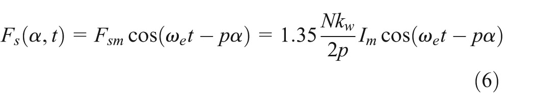
where Fsm is the fundamental amplitude of stator MMF.
Considering the influence of air gap MMF produced by the motor rotor torsion angle and according to the space position relations between the stator MMF and the rotor MMF shown in Figure 1, air gap MMF can be obtained

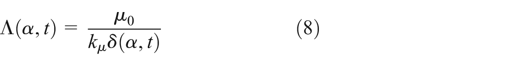
The electromagnetic torque of the motor for hybrid electric vehicle (HEV) can reach 300% of the rated torque, and at the same time, the speed can reach 200% basic speed and higher. According to the above, the motor is easy to run in the magnetic field saturation region. The magnetic saturation coefficient kµ is introduced to consider the effect of magnetic saturation. The air gap of the permanent magnet synchronous motor is
Then, the energy of air gap magnetic field of permanent magnet synchronous motor can be obtained

where R is the average radius of the air gap, and l is the effective length of the rotor.
When the torsion angle of the rotor is φ, the electromagnetic torque is
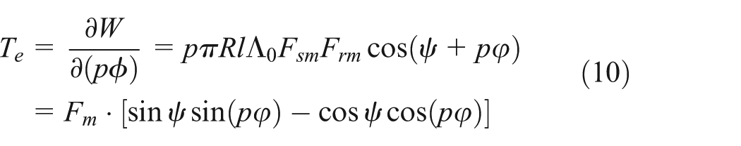
where
Because of the torsional angle of the rotor φ ≈ 0, the approximate formula of the triangle function can be carried out using sin x ≈ x and cos x ≈ 1, and then, the electromagnetic torque of the rotor can be obtained

where Fm = πRlΛ0FsmFrm, k0 = Fm cos ψ, and k1 = pFm sin ψ; k0 and k1 are the electromagnetic parameters, and they are related to the characteristic parameters of the motor.
It can be seen from formula (11) that the steady-state electric torque is identical with that of the literature 20 when not considering the influence of the torsion angle of the rotor on the MMF.
Electromechanical coupled torsional vibration model
Rotor torsional vibration model
The shaft system is simplified and equivalent to two-mass mechanically coupled rotor model to analyze the electromechanical coupling of the rotor system in the permanent magnet synchronous motor drive system, which is shown in Figure 2. The rotor of permanent magnet synchronous motor is connected with the mechanical rotor by an elastic joint. And the motor frame is assumed to be rigid. Te, TL, ϕ1, and ϕ2 are the electromagnetic torque, load torque, angle for permanent magnet synchronous motor, and the angle load inertia, respectively.

Two-mass electromechanical coupling rotor system.
According to Newton’s law, the torsional vibration dynamic equations of the two-mass rotor system are written as
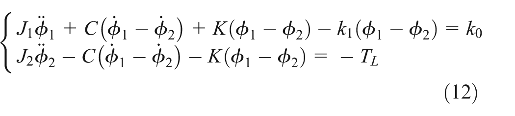
When the load torque and electromagnetic torque are constant values, the rotor of the mechanical angular speed Ω is constant. So, it can be assumed that

Ignore the system shaft damping, namely, C = 0, and when the system is in a dynamic balance, k0 =average(TL) = TL0. If

where
System active vibration reduction method
Picking up one term of the summation such as cv·sin(vα + ψv) and then solving equation (14), the following can be obtained

where
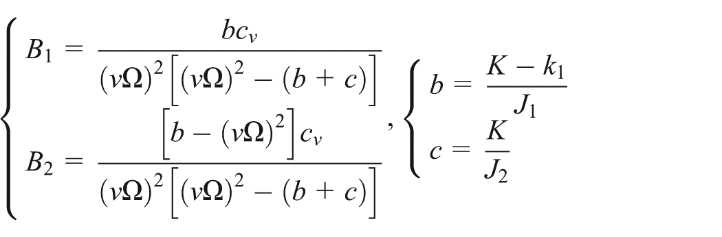
Thus, if b = (vΩ)2, namely, k1 = K − J1(vΩ)2, then B2 = 0. At this time, the motor oscillates large amplitude, while the load does not oscillate, so the motor has a certain vibration damping effect on the drive system.
System simulation analysis
Numerical simulation analysis of the torsional vibration is carried out, and the result is shown in Figure 3. The simulation system parameters given in Table 1 belong to a 60-kW PMSM.

System torsional vibration responses.
The simulation system parameters.

We can conclude from Figure 3 that under the existing system parameters and load operating conditions, a certain torsional vibration exists in the system; the vibration of the motor rotor is shown in Figure 3(a) and the torsional vibration of the load inertia part is shown in Figure 3(b). Figure 3(c) and (d) is the FFTs of the previous figure. And the two figures indicate that the torsional vibration of these two parts is large and need to be reduced.
The system parameters for reducing torsional vibration can be obtained from equation k1 = K − J1(vΩ)2 and given in Table 2. Compared to Table 1, the stator current Im and the Ampere turns of Each phase winding N are changed to the value 300 and 1200, respectively, to reduce the vibration.
The system parameters for reducing torsional vibration.

The simulation and analyzing of the torsional vibration is carried out using the system parameters given in Table 2. And the response of the torsional vibration is shown in Figure 4. From the Figure 4, it is concluded that the vibration of the PMSM for the parameter of reducing torsional vibration is obvious smaller than that of original system.

Improving system parameters to reverse the vibration response.
In comparison with Figure 3, the modified system parameters can be used to control the torsional vibration of the system. From Figure 4(c) and (d), it is concluded that the torsional vibration of the driving part can be reduced effectively by the torsional vibration of the system parameters, and the vibration amplitude of the motor can be reduced effectively.
Braking energy recovery system vibration reduction measures
As shown in Figure 5, for the electromagnetic braking condition in mechanical and electrical composite transmission system, the permanent magnet synchronous motor is affected by the electromagnetic resistance. The power required for braking is very large; if it is not controlled, the permanent magnet synchronous motor required not only has a large cost but also has a very large size. However, after the control of the permanent magnet synchronous motor with equal power control, there is strong electromechanical coupling effect between the permanent magnet synchronous motor and load inertia, which needs to be analyzed in order to design the two systems.

Schematic diagram of the two-mass mechanical and electrical coupled rotor system.
System control structure
The control objective in the electromagnetic braking condition of permanent magnet synchronous motor is to control the power of the system, in order to avoid series of mechanical and electrical failure caused by the system overload. The motor controller needs to meet the following conditions: (1) the system power should be kept constant in order to maximize the recovery of braking energy and (2) the system does not have the phenomenon of increasing the torsional vibration of the system.
In general, the system should use the maximum output power control strategy, in order to maximize the use of the power of the motor. The control block diagram 21 is shown in Figure 6. From the maxim power curve and measured rotor speed, the operation power P* is obtained. Through the power difference ΔP*, the objective P and the PI controller are used to calculate the objective torque Te.
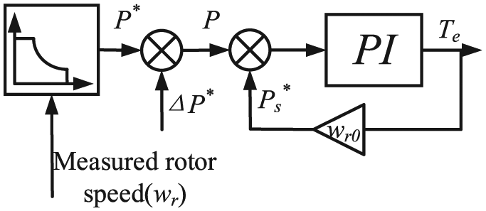
Control strategy diagram of permanent magnet synchronous motor.
The power of the permanent magnet synchronous motor is determined by the maximum power curve of the motor. And the power is controlled by the d-q axis current of the inverter. Assuming that the d-axis is the same as the stator flux linkage, the q axis is ahead of the d-axis 90. The voltage and current equations of the motor are as follows
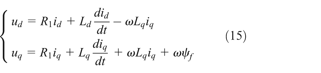
where R1 is the stator winding resistance of each phase; Ld and Lq are the stator d-axis and q-axis inductance, respectively; ω is the rotor electrical angular velocity; and ψf is the permanent magnet flux in the d-q coordinate system.
The power of permanent magnet synchronous motor is

In the control block diagram of Figure 2, the two PI controllers control the motor’s power and the q-axis current, respectively, thus completing the control of the system.
Electromechanical coupled torsional dynamics
For the rotor system shown in Figure 5, the torsional vibration dynamic equation is neglected

The two equations can be subtracted as

Assuming that the load inertia rotational speed in torsional vibration is constant, and we know that ϕ12 = ϕ1- ϕ2, due to the equal power condition, it is inverse relationship between the permanent magnet synchronous motor electromagnetic resistance torque and rotational speed. Then, we can make De = dTe/d(Δωr). And with Δωr = dφ12/dt, equation (16) can be simplified to two-order vibration differential equation of standard form

From formula (18), it can be concluded that De/J1 should be greater than 0 or the amplitude of Δϕ12 will increase with the extension of time. For the maximum power output of the motor, Figure 7 shows the relationship between the torque and the speed of the motor which is modeled by the system parameters in Table 1 under the steady-state conditions.

Relationship between the torque and the speed of the motor.
It can be seen from Figure 7 that when the motor is in the generator mode, the electrical damping De = dTe/dωr < 0, and then the vibration expressed by equation (3) is unstable. As a result, the oscillation of torsional angle Δϕ12 and the corresponding torque oscillations ΔTc (ΔTc = KΔϕ12) will grow with time.
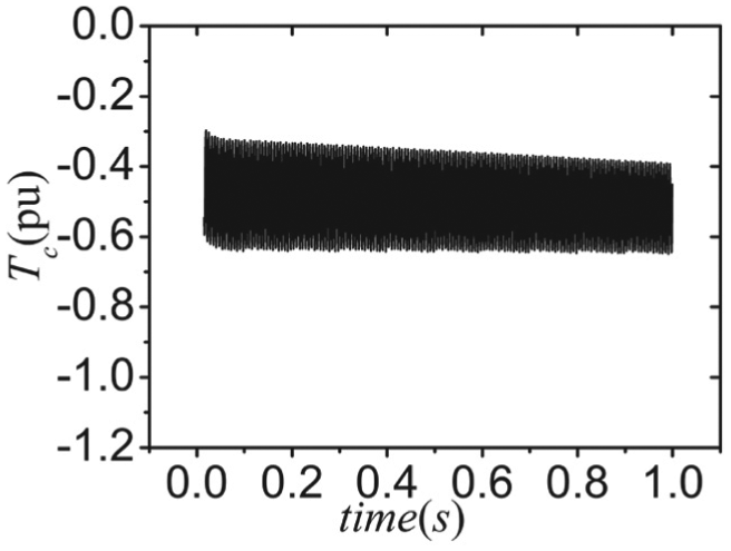
Figure 8 shows the simulation results of torsional vibration of electromechanical coupled system under the condition of equal power control strategy. In Figure 8, Tc is the torque tolerated by the shaft, which is calculated by Tc = k(φ1 − φ2).
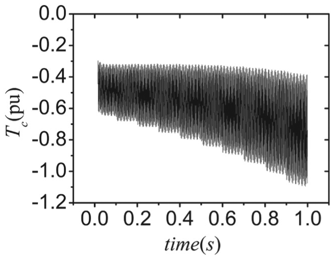
Simulation results with equal power control strategy.
As can be seen from Figure 8, the power control strategy, due to the electrical damping De < 0, and the system’s torsional moment oscillation amplitude are not stable. In order to make the electrical damping De = dTe/dωr > 0, in the process of equal power control, the target power can be changed accordingly, so that the output power fluctuates in the original power and the electrical damping is greater than 0. The control mode can be considered as a variable power control. The torque and rotational speed are shown in Figure 9.

Torque and rotational speed of motor under variable power control.
The control strategy is shown in Figure 10. As illustrated in Figure 6, from the variable equal power curve and measured rotor speed, the operation power P* is obtained. Through the power difference ΔP*, the objective P and the PI controller are used to calculate the objective torque Te.
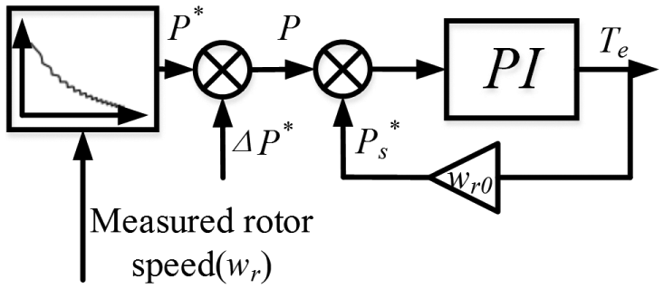
The control strategy under variable power control.
Figure 11 shows the simulation results of torsional vibration of electromechanical coupled system under the control strategy of variable power control in the mechanical and electrical engineering.

Simulation results under variable power control strategy.
As can be seen from Figure 11, the torsional vibration of the system tends to be stable by De > 0, and the torsional moment of the system is getting smaller and smaller.
Frequency domain analysis of electrical damping
Combining the relationships between speed and torque shown in Figure 9 with the variable power control strategy shown in Figure 10, it can be obtained that P = P* + ΔP*. Where P* is a constant value, namely, the maximum output power of the system. ΔP* is a sawtooth wave signal with time at zero fluctuation. It is ΔP*, which makes the symbol of the electrical damping De change. We can conclude from Figure 10 that

where

Moreover,

where the parameter A is obtained by the result of the method. We can change the parameter A in order that the result could approach to reduce the vibration. Then

Sequentially

The electrical damping De can be obtained by the following formula
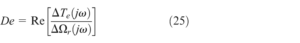
Figure 12 shows the changing relationship between the electrical damping and the frequency when the parameter A = 1. As shown in Figure 12, the electrical damping is positive in the working speed. When the parameter “A” changes, the electrical damping also changes. Figure 13 compares the changes of the electrical damping among variable parameter A.

The relationship between electrical damping and frequency domain.

The relationship between the electrical damping and the frequency.
As shown in Figure 13, the electrical damping increases with the increase in the amplitude of the power. By numerical simulation, we can get two kinds of torsional moment oscillations of the system which are shown in Figures 14 and 15.

Simulation results of time varying power control strategy when A = 0.4.
Simulation results of time varying power control strategy when A = 0.1.
From Figures 14 and 15, it can be seen that reducing the parameter “A” could lead to reducing the electrical damping of the system. Then, it can be concluded that we could use the variable power control strategy in the PMSM to reduce the torsional vibration of the electromechanical system.
Conclusion
In this article, the active vibration reduction method and the improved control strategy are proposed to provide a theoretical basis for the vibration reduction in mechanical and electrical coupling, which provides reference for the design of electromechanical systems in the hybrid electrical vehicles. The following inferences are drawn:
The mechanical and electrical torsional vibration model is established in this article, which provides a basic theory for the active vibration control of the system.
Active vibration analysis is carried out for the electromechanical coupled torsional vibration model. The simulation results indicate that the optimized calculation of the mechanical and electrical coupling system parameters can effectively reduce the torsional vibration, especially the torsional vibration of the load inertia part.
When the mechanical and electrical power transmission system is operated in the braking energy recovery condition, the mechanical and electrical coupling, the electric motor, and other power control will cause the system to produce a negative effect on the electrical damping. The improvement in the control strategy of the electric motor is presented, which can make the electrical damping positive, thus reducing the vibration of the motor.
Footnotes
Academic Editor: Hamid Reza Shaker
Declaration of conflicting interests
The author(s) declared no potential conflicts of interest with respect to the research, authorship, and/or publication of this article.
Funding
The author(s) disclosed receipt of the following financial support for the research, authorship, and/or publication of this article: This work is supported by the National Natural Science Foundation of China (NSFC) “51305032.”