
Abstract
In aircraft assembly, frames are usually used as the skeleton shape benchmarks of a fuselage panel to locate other parts accurately, thereby coordinating the relative position relationships between each part. In order to guarantee the assembly quality, a methodology for analyzing the effect of positioning errors of frames on fuselage panel assembly deformation is proposed. A finite element model of the fuselage panel is established first and then a mathematical model for representing the assembly deformation is derived. To contain more assembly deformation information, the optimal measurement point placement method is adopted to extract a set of finite element nodes as the measurement point locations from a large candidate set. Meanwhile, the mathematical relationship between the position errors of measurement points and the positioning errors of frames is also determined, which is then combined with the Monte Carlo simulation and the grey relational analysis to quantitatively analyze the impacts of the positioning error(s) generated by single or multiple frames on fuselage panel assembly deformation.
Introduction
In aircraft assembly, a fuselage panel is generally assembled by numerous parts according to the design criteria and technical requirements, and factors such as the environmental temperature, the non-nominal shape of parts, the non-nominal location, and deteriorated condition of tooling can cause the fuselage panel assembly deformation. Besides, some forces, for example, joining forces or internal stresses acting on the part can also generate adverse effect on fuselage panel. Since the stiffness of frames is commonly larger than that of other thin-walled components such as stringers, skins, and clips, aviation enterprises usually use frames as skeleton shape benchmarks and then adopt special assembly jigs to orderly locate and clamp other components in order to coordinate the relative position relationships exactly between each part and guarantee the dimensional integrity of the whole panel. Therefore, the positioning errors of frames can directly affect the overall assembly accuracy of the fuselage panel. In order to guarantee the panel assembly quality, it is essential to analyze the impacts of positioning error(s) generated by single or multiple frames on fuselage panel assembly deformation and provide guidelines for optimizing the panel assembly process.
Assembly deformation is one of the most important issues in the assembly of non-rigid components, especially in automobile and aerospace industries. Currently, the deformation analysis of non-rigid assemblies has attracted many researchers. Liu and Hu 1 first proposed the method of influence coefficient for variation “stack-up” analysis in sheet metal assemblies. Merkley 2 developed the theory and general methods for performing tolerance analysis on assemblies of compliant parts, where the tolerances must account for allowable assembly stress and fit. Camelio et al. 3 extended Liu and Hu’s approach to multi-station systems using state-space representation by incorporating sources of variation from parts, tooling, and their interactions. Yu et al. 4 presented a new variation model of compliant sheet metal assembly with consideration of material variation influence. For the purpose of reducing assembly deformation, diagnosing the sources of dimensional variation for compliant parts is also essential. Camelio et al. 5 presented a methodology to determine the optimal locations of sensors on the parts by applying the effective independence (EfI) method so that different diagnostic vectors can be distinguished from each other. Camelio and Yim 6 developed a method for the diagnosis of the variation contribution of assembly components using measurement data from the final assembled products in order to reduce assembly deformation. Up to now, most of the researchers are mainly concentrated on the automotive assembly field, while in the aircraft assembly domain, some researchers have also made efforts to study the assembly deformation of aircraft parts such as wing and fuselage. Liu et al. 7 established a wing panel assembly error transfer model. Saadat et al.8–10 used the finite element (FE) method and experiments to predict wing box assembly variation and location geometric deformation, and they also developed a method to estimate the position errors encountered in the assembly of wing rib components. Cheng et al.11,12 established the variation model of aeronautical thin-walled structures with multi-state riveting. Bi et al. 13 proposed a method to predict and correct the assembly deformation of a large fuselage panel during digital assembly using an FE analysis and partial least squares regression method. Lin et al. 14 used unified substructures with consideration of identical parts to analyze compliant assembly variation of aeronautical panels.
For a fuselage panel, one of the most important factors that affect its assembly quality is the positioning accuracy of frames, which, unfortunately, has not been investigated deeply and widely. Besides, most of the researchers did not quantitatively analyze the impacts of the positioning error(s) generated by single or multiple key components, and most of the automotive parts or aeronautical panels are composed of different parts which cannot be identical with each other as mentioned in Lin et al. 14 Considering that the non-nominal location of frames is a primary variation source that can affect the fuselage panel assembly deformation, in this article, the fuselage panel assembly deformation induced by a certain individual frame is analyzed and compared, which can be adopted to determine the different importance of each frame according to actual assembly requirements. Besides, the effect of the positioning errors generated by multiple frames on the fuselage panel assembly deformation is also reflected, which, in turn, can better adjust and control the deviations of locator variation sources on frames. The format of the remainder of this article is organized as follows. In the next section, a fuselage panel FE model is created, whose boundary conditions are based on the “N-2-1” locating principle. 15 Following this, a model of the fuselage panel assembly deformation is established considering the positioning errors of frames. Next, the placement of measurement points is optimized based on the EfI method in order to cover more assembly deformation information. Then, the mathematical relationship between the position errors of the measurement points and the positioning errors of frames is determined, and the impacts of the positioning error(s) generated by single or multiple frames on fuselage panel assembly deformation is analyzed based on the Monte Carlo simulation (MCS) and the grey relational analysis (GRA). The MCS is always used to predict uncertainties in the “real world.” So, it may also be used to simulate tolerance stack-up in mechanical assemblies. The GRA is a data process method used to sort out the correlation extent of effect factors in a system with uncertain information. Finally, the last section concludes the article.
Fuselage panel modeling
FE model
As depicted in Figure 1, to obtain the optimal placement of the measurement points, a detailed FE model of a fuselage panel selected from a military transport plane is established by ABAQUS. 16 Parts such as frames, skin, and stringers are modeled by C3D8I elements, which are enhanced by incompatible modes to improve the bending behavior and eliminate artificial stiffening due to Poisson’s effect in bending. Besides, only one element layer is meshed in the thickness direction of each component. Seven frames (I, II, …, VII) are distributed along the y direction, and eleven stringers along the circumferential direction are indexed from A to K.
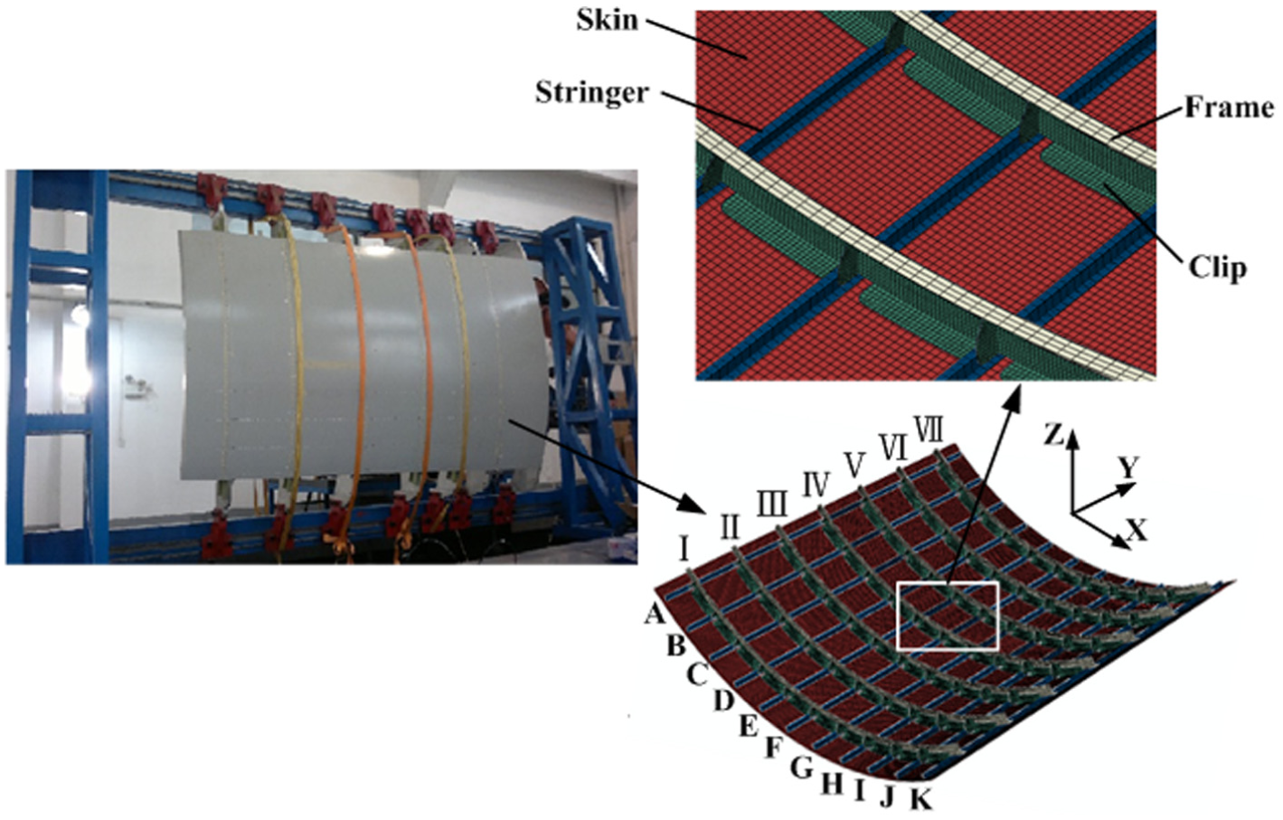
Fuselage panel model.
Components of the fuselage panel are usually connected by rivets and bolts, which can keep the position relationships between each part unchanged. Tie constraints are used so that there is no relative motion between each component. Shim material is not considered because the FE model is established according to the theoretical model, and no gap will be generated. Similarly, the main role of sealant material is to guarantee the air tightness, and it cannot strengthen the structural intensity, so the FE model does not also contain sealant material.
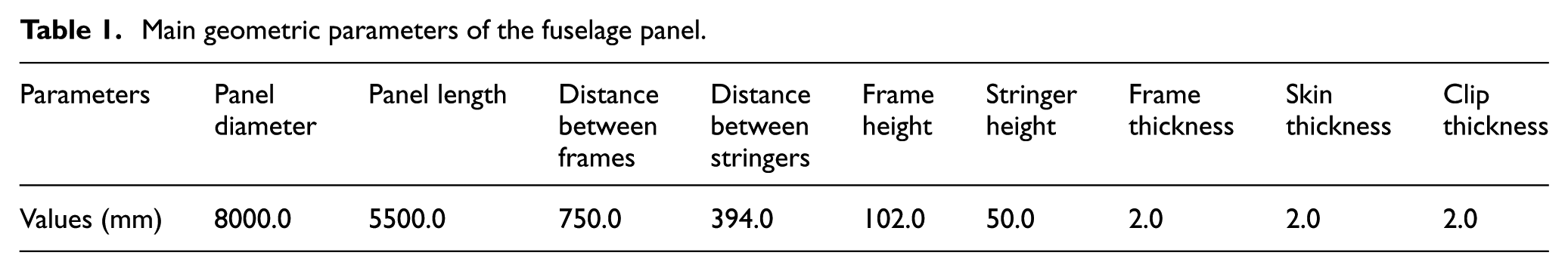
The material of the skin is 2024-T4 with Young’s modulus 73 GPa and Poisson’s ratio ν = 0.33, and the material of frames, stringers, and clips is 7050-T7651 with Young’s modulus 72 GPa and Poisson’s ratio ν = 0.33. 17 The main geometric parameters of the panel are listed in Table 1.
Main geometric parameters of the fuselage panel.
Boundary conditions
In traditional assembly, parts are usually located according to the “3-2-1” principle. 18 However, since thin-walled parts are prone to bending and buckling, constraining the rigid body motion (i.e. 6 degrees of freedom (DOFs)) by the “3-2-1” principle is not sufficient. Therefore, the fixturing system for thin-walled parts generally requires N > 3 locators on its primary datum, where N is determined by the dimensional specification of the part. It can also be shown that exactly two locators on the secondary datum and one on the tertiary datum are needed, respectively, to determine the part uniquely.
According to the dimension of the fuselage panel, six locators are used to restrain the out-of-surface motion and excessive deformation. Locators are the same as rigid point contacts which can constrain any one or more of the 6 DOFs of frame parts at contact points. From this perspective, in assembly simulation model, locators can be regarded as mechanical stops to achieve corresponding DOF constraints in the element coordination systems. As can be seen from Figure 2, locator 1 marked as “▲” restrains the translational DOFs in the x, y, and z directions; locators 2, 3, 4, and 5 marked as “•” just restrain the y-direction translational DOF; and locator 6 marked as “◆” restrains the translational DOFs in the y and z directions. The whole model contains 42 locators in all and their positions are listed in Table 2, where d is the distance between two neighboring frames (see Table 1), and p is an integral number ranging from 1 to 7, which corresponds to the frame index.

Locating scheme of a frame.
Coordinates of the locators.
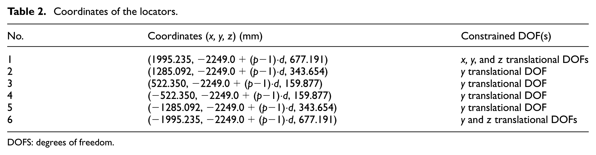
DOFS: degrees of freedom.
Modeling fuselage panel assembly deformation
Supposed that the data from m measurement points compose the assembly deformation of the fuselage panel

where

Deformation response to a unit displacement in the x translational direction of the first locator.
If it is necessary to improve the proposed method, other deformation patterns caused by factors such as gravity and environmental temperature can also be further introduced conveniently into the method using FE modeling.
Optimal measurement point placement
Generally, the assembly deformation

where
As can be seen from equation (2), the best set (say, set Ω) of the measurement points from the initial candidate measurement point set (say, set Ψ) should minimize

Equivalently, equation (4) can be used to evaluate the estimate error of

where

where
According to the FE model, each column vector
Step 1. Calculate the FIM

Step 2. Assume that the eigenvector matrix and the eigenvalue matrix of

where the symbol “⊗” represents element-by-element matrix multiplication.
Step 3. Each row of

where
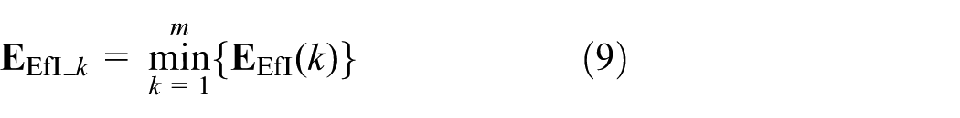
Step 4. Search the element whose effective independence
Step 5. Remove the kth measurement point from Ψ and delete the rows from 3k−2 to 3k in
Step 6. If the number of the measurement points remained in Ψ has been reduced to the desired number m
To gain the optimal measurement point placement on the fuselage panel, the FE nodes are used as measurement points. Considering that it is impossible and impractical to select all nodes of the FE model as measurement points, in this article, partial nodes on each frame are chosen to compose the set of the initial candidate measurement points.
As can be seen from Figure 4, the lateral surface of the frame is 64 mm in width, and the distance between two neighboring nodes along the circumferential direction is 36 mm. To make a trade-off between economy and accuracy, 237 candidate nodes are selected from a frame part; thus, the set Ψ of the initial candidate nodes contains 1659 nodes, whose indices in the FE model are 240381I–240617I, 242163II–242399II, 243945III–244181III, 245727IV–245963IV, 247509V–247745V, 249291VI–249527VI, and 251073VII–251309VII, respectively.

Initial candidate nodes of a frame part.
The number of locator variation sources in the model is
Optimal measurement point placement results.

Substituting
Assembly deformation analysis
Theoretically, more historical data are needed in order to get better modeling accuracy. However, in aircraft assembly processes, due to the long-period assembly cycle and limited sorties, it is difficult to obtain many historical data in the short term. Therefore, the MCS is adopted to achieve more data. The MCS is widely used in many scientific and engineering applications. The MCS for variation simulation is achieved through a total number of n deterministic simulations, where n is the sample size. Normally, n is a large number in order to ensure the accuracy of the simulation results. Besides, the confidence intervals for output in the MCS can also be estimated. However, too many data will make it difficult to analyze and compare the fuselage panel assembly deformation induced by a certain individual frame, so instead of using the EfI method,22–24 the GRA is adopted to establish an evaluation criterion, which can be used to determine the different importance of each frame.
Based on the experience of some relevant assembly workers who longtime engage in fuselage panel assembly, the locator variation sources on each frame in the x, y, and z directions are supposed to follow the normal distributions (−0.008, 1.1152), (−0.005, 0.5122), and (0.006, 1.1372), respectively. Different hypothetical values will generate different analytical results, but the method proposed in the article is feasible to any set of data. The MCS-based method is adopted to generate the stochastic sample data
Assume that the theoretical coordinates of the measurement points are

where

where

To analyze and compare the fuselage panel assembly deformation induced by a certain individual frame, the GRA proposed by Deng
26
is adopted. Theoretically, the posture deviation in the x direction is 0, so
Step 1. Initialize


Step 2. Calculate the deviation sequences

Step 3. Calculate the grey relational coefficient

where
Step 4. After obtaining the grey relational coefficient, we normally take the average of the grey relational coefficient as the grey relational grades

Similarly, the grey relational grades
The MCS for analyzing the assembly deformation induced by a certain individual frame part is achieved through a total number of n runs. Normally, n is a large number, typically hundreds to thousands, here, for the GRA, n = 2000.
The grey relational grades

Grey relational grades
Similarly, Figure 6 illustrates the grey relational grades

Grey relational grades
The GRA points out that the positioning errors of different frames can affect the fuselage panel assembly deformation in different extent, and it is necessary to comply with actual assembly requirements in order to determine the different importance of each frame. Besides, above analysis is carried out only considering the influence generated by the positioning error of a certain individual frame, analyzing the fuselage panel assembly deformation induced by the positioning errors of all frames at the same time is also important, which can further determine the confidence intervals for the mean values and standard deviation values of posture parameters.
To express the posture intuitively,
where

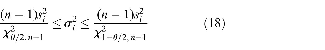
Similar to the true variance, the confidence interval for the mean of the component fi can also be estimated. Denote

where
A confidence interval is always calculated by first selecting a confidence level, which is a measure of the degree of reliability of the interval. Generally, the higher the confidence level, the more strongly we believe that the value of the parameter being estimated lies within the interval. In this article, a 95% confidence level is adopted for both the true
Confidence intervals for the true µi and 3σi.
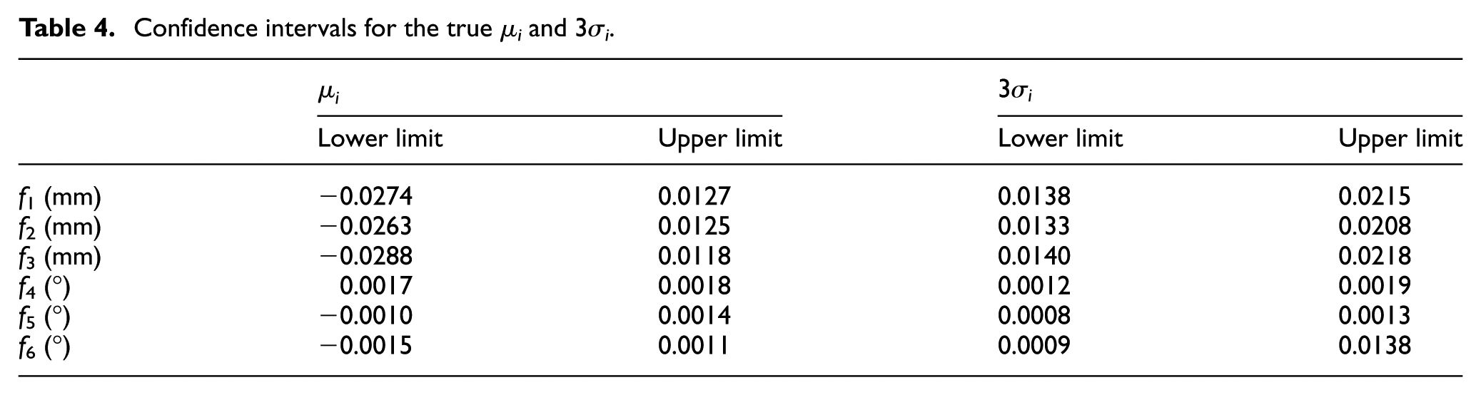
Besides, as can be observed from equations (19) and (20), both confidence intervals of

Convergence behavior of the MCS for estimating the (a) mean values and (b) variance values of the position errors of measurement points in the x direction.

Convergence behavior of the MCS for estimating the (a) mean values and (b) variance values of the position errors of measurement points in the y direction.

Convergence behavior of the MCS for estimating the (a) mean values and (b) variance values of the position errors of measurement points in the z direction.
Conclusion
In the large aircraft assembly process, one of the most important preconditions to guarantee the assembly accuracy is to control the fuselage panel assembly deformation, while in the subassembly processes, frames are usually used as the skeleton shape benchmarks of the fuselage panel to locate other parts accurately, so their positioning errors are the primary factors that affect the fuselage panel assembly deformation, and the impacts of the positioning error(s) generated by single or multiple frames on the overall assembly deformation of the fuselage panel are quantitatively analyzed in this article. The major conclusions can be described as follows:
Since the fuselage panel assembly deformation is usually represented by the position errors of measurement points, the mathematical relationship between the position errors of measurement points and the positioning errors of frames is established.
For the purpose of covering more deformation information of the fuselage panel, the placement of measurement points on the fuselage panel is optimized according to the EfI method, and 48 FE nodes are selected as the measurement points.
The results of the GRA indicate that the positioning errors generated by different frames can affect the fuselage panel assembly deformation in different extent. Besides, the MCS-based method is adopted to analyze the fuselage panel assembly deformation induced by the positioning errors of all frames, and the confidence intervals for the true mean values and standard deviation values of the posture deviation parameters are determined.
There are many factors that can cause the fuselage panel assembly deformation, such as the environmental temperature of the assembly workshop, the non-nominal shape and size of parts, the non-nominal location and deteriorated condition of tooling, and imperfect joining. Each error source will lead to a different degree of deformation and ultimately affect the whole aircraft assembly quality. This article analyzes the fuselage panel assembly deformation only considering the positioning errors of frames, while other error sources that impact the panel assembly quality are also worthy of in-depth study.
Footnotes
Academic Editor: Xichun Luo
Declaration of conflicting interests
The author(s) declared no potential conflicts of interest with respect to the research, authorship, and/or publication of this article.
Funding
The author(s) disclosed receipt of the following financial support for the research, authorship, and/or publication of this article: The work described in this paper has been supported by grants from the National Natural Science Foundation of China (No. 51275463) and the Science Fund for Creative Research Groups of National Natural Science Foundation of China (No. 51521064).