
Abstract
The structural flexibility, nonlinear friction, and backlash are the major factors limiting the control performance of precision transmission systems. If uncompensated, these factors compromise the positioning and tracking accuracy of precision transmission systems and even cause limit cycles and oscillation. In this article, a framework for integrated design from dynamic modeling to controller design is proposed. A multi-state dynamic model is presented, which can unify the modeling for a multi-state, discontinuous system including the motor state, the motion state, the mechanical contact state, and the friction state. Then, a control design method related to the dynamic modeling using perturbation separation of the model parameters is presented. Using the proposed modeling method, a continuous dynamic model is established to include all different partition models. The model comprehensively describes the mechanical and electrical characteristics of the precision transmission system. A robust controller is designed using the proposed control method. Experimental results demonstrate that the proposed modeling method is accurate and the proposed control method significantly improves accuracy and robustness of the controller compared to traditional control methods.
Introduction
Precision transmission systems have been widely used in industrial manufacturing. Performance standards of precision transmission systems are becoming stricter in accordance with improved machining accuracy.1,2 To achieve the increased requirements of steady state, tracking, and transient performances, the dynamic change of the precision transmission system cannot be ignored when designing the controller. The dynamic behavior is usually caused by coupled factors including non-smooth nonlinearities such as friction and backlash, mechanical system dynamic performance variables such as varying transmission ratios and the changing payload, and the motor dynamic characteristics. The motion accuracy is greatly affected by these factors.
Friction is a nonlinear phenomenon present in the motion of bodies in contact, which can cause control problems, such as static errors, limit cycles, and stick-slip effect, limiting the performance of the system. In precision transmission systems, it is essential to assure good dynamic characteristics by compensating friction. A precise friction model is necessary in the design of friction compensators. Many friction models were developed to describe the phenomenon of friction. According to whether differential equations are used, friction models can be broadly divided into two categories: static friction models and dynamic friction models. 3 In the static friction models, friction is described as a function of the relative velocity. Static friction models include Karnopp model, Armstrong model, and classical models which are different combinations of Coulomb friction, viscous friction, and Stribeck effect.3,4 In dynamic friction models, friction is described as a function of the relative velocity and displacement. Dynamic friction models include Dahl model, Bliman–Sorine model, Bristle model, Reset integrator model, LuGre model, Leuven model, and generalized Maxwell slip. 3 Dynamic models can describe the nonlinear behavior of friction more accurately. However, there is a serious drawback: model parameter identification is difficult in practice. Hence, compensation techniques based on static friction models are still needed in practical applications. 5 It is essential in controller design to reduce the effects of friction on a closed loop. 6 In previous works on friction compensation, there exist three major trends: compensation using soft computing methods, observer-based friction compensation, and model-oriented friction compensation techniques.7,8 The nonlinear part of the friction model is compensated using a fuzzy system in Garagic and Srinivasah 9 and Mostefai et al. 10 Coulomb friction compensation with a reduce-order observer has been proposed in Barabanov and Ortega. 11 A sliding mode adaptive control with observer is studied for servo actuators. 12 Based on nonlinear parameterizable friction, a Lyapunov-based tracking control is proposed in Makkar et al. 13 A novel continuously differentiable nonlinear friction model is first derived by modifying the traditional piecewise continuous LuGre model. 14
Backlash exists in every transmission system where a driving member (motor) is not directly connected with the driven member (load). 15 Backlash is a common phenomenon in transmission systems. 16 Compensation of backlash has attracted research efforts for several decades and there still exist many theoretical and practical problems. 15 The first approach to backlash compensation is identification of backlash and implementation of backlash inverse. 17 This approach usually requires the location of the backlash block to satisfy certain conditions, since a direct cancelation requires the backlash to be at the plant input. The second approach is to design a linear robust controller, which is a stabilizing controller, robust enough to cope with the backlash effect. 18
In the previous works, the controllers were designed to compensate friction or backlash individually. In practice, however, friction and backlash often coexist. Few studies deal with the control of systems by compensating both backlash and nonlinear friction.5,19 A controller accounts for not only the structured uncertainties but also the unstructured uncertainties is proposed. 20 Furthermore, in almost all of the studies, the motor dynamic characteristics and the dynamic performance variables of the mechanical system are ignored. In order to improve the control precision and provide the guidance of dynamic design, a framework for integrated design from dynamic modeling to the controller design is proposed in this article. A multi-state dynamic modeling is proposed, which describes friction, backlash, motor dynamic characteristics, and structural flexibility simultaneously and can be easily introduced in robust controller design. A robust control method of perturbation separation of the parameters introduced in the model is also proposed.
The rest of the article is organized as follows: in section “System descriptions and modeling,” a multi-state dynamic modeling method is proposed to describe the precision transmission system. In section “Parameter identification of the dynamic model,” the parameters of the derived model are identified, and the accuracy of the model is validated by experimental results. In section “Robust controller syntheses,” a new high-performance robust controller is designed. The effectiveness and robustness of the controller is also validated by experimental results. Finally, section “Conclusion” concludes this study.
System descriptions and modeling
Figure 1 shows the setup of a typical precision transmission system. In the transmission part of the system, there are a motor, a two-stage reduction gear, a screw, a nut, and a fork-lever which are typically machine parts. The two-stage reduction gear is composed of a double cylindrical gear and two cylindrical gears. The mechanical transmission ratio is modified by the screw and the nut. The friction and backlash which can cause system instability exist between the gear, screw, nut, and fork-lever. Hence, a typical precision transmission system can be divided into four distinct entities: the mechanical system, the disturbance generating system, the controller, and the spec generating system. The controlled system, which consists of the mechanical system and the disturbance generating system, is manipulated to reach the desired specs by the controlling system including the controller and the spec generating system.

Structure of a typical precision transmission system.
In the typical transmission system studied in this article, the mechanical system is used to convert high-speed rotary motion to low-speed rotation. The control performance is affected by the undesirable effects from the disturbance generating system. In a typical transmission system, the disturbances are divided into three parts: friction and backlash caused by the gear, screw, nut, and fork-lever; the load change and transmission ratio change; and the motor dynamics characteristics. These disturbances must be taken into account in modeling. The spec generating system generates a number of desired trajectories for the mechanical system. The controller manipulates the motor to force the mechanical system to the desired trajectories according to certain rules, which are the focus of the design.
Friction and backlash exist between gears, screw, nut, and fork-lever. The backlash effects between the nut and fork-lever are particularly significant. The friction effects in the fork-lever also deserve most attention. Hence, ignoring the dynamic behavior of non-movement direction, the dynamic model of the mechanical system is sketched in Figure 2.
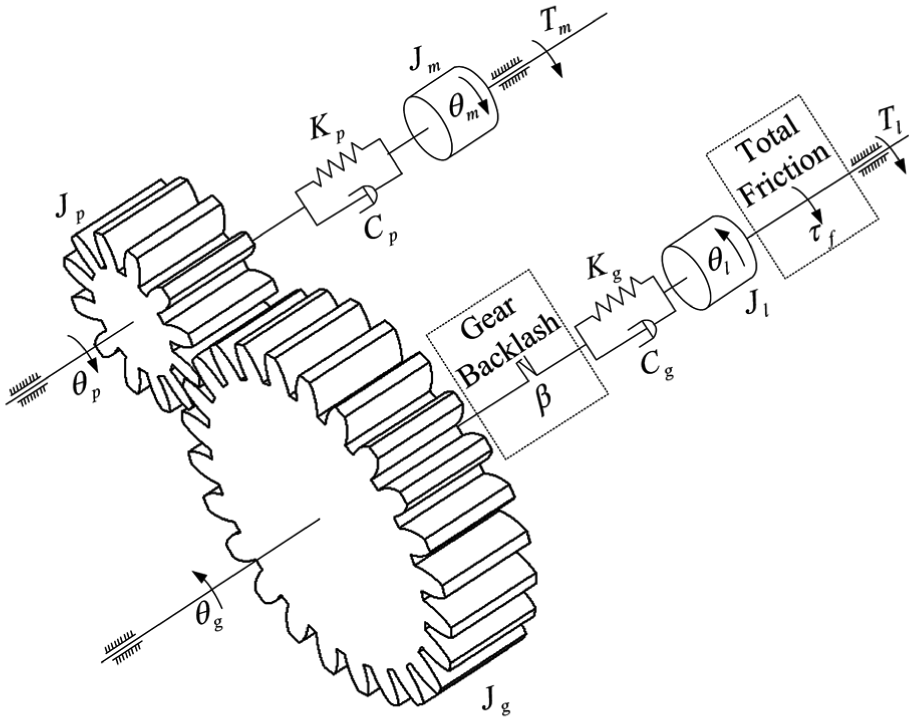
Dynamic model of mechanical system.
In order to describe the mechanical system and the disturbances accurately and sufficiently, the mechanical system is split into four rigid bodies in which the quality of transmission shafts is ignored. The first rigid body contains the motor. The second rigid body contains the first cylindrical gear. The third rigid body contains the double cylindrical gear, the second cylindrical gear, the screw, and the nut. The fourth rigid body contains the fork-lever. The interconnection of the first and second body is a linear torsion spring and damper. The interconnection of the second and third body is a gear pair, which represents total transmission ratio of mechanical system. The backlash, together with the linear torsion spring and damper, exists between the third and fourth body.
Define
Contact mode (if

Backlash mode (if

where
The input torque

where
In order to accurately describe friction of the mechanical system, a friction model combining stiction, Coulomb friction, viscous friction, and Stribeck effect is adopted. Taking into account the difference of friction in positive and negative directions, the friction model can written as

where
The nonlinear friction model in equation (4) is difficult to be applied in controller design when backlash is also present in the controlled mechanical system. Assume that the fork-lever moves in the

where,
Based on the above expressions, it can be easily inferred that the friction behaves are different in the low-velocity and high-velocity regimes. If the absolute value of the velocity is smaller than
If the system is in backlash mode

If the system is in contact mode

In the above model, the linear approximate friction varies with the fork-lever angular velocity. Note that transmission ratio h and payload

Obviously,
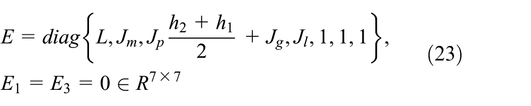
Then, a multi-state dynamic model is derived, which includes the electric state and different dynamic states of all cases

where


Parameter identification of the dynamic model
Parameter identification
The imperfection of the transmission model leads to undesirable behaviors in the system. Therefore, proper parameter identification of the system dynamic model is important for realizing good performance. There are five types of parameters to be determined: the inherent property parameters of the mechanical system; the electrical parameters; and the corresponding coefficients of the friction model, the backlash gap size, and the maximum payload of the mechanical system.
The inherent property parameters of the mechanical system include inertia of each rigid body, stiffness and damping coefficients of each spring, and transmission ratio. The rigid body inertias are calculated based on the shape and size of the corresponding components. The spring stiffness and damping coefficients are obtained through the finite element analysis of corresponding components using the ANSYS FEM software package. The transmission ratio, which varies with the fork-lever angle position, can be expressed as

where
The friction curve, which is depicted in Figure 3, is obtained from a closed-loop experiment where the precision transmission system is controlled with a proportional–integral–derivative (PID) controller at several constant velocities and the input torque at a constant velocity is assumed to be equal to the friction torque. The coefficients of friction model, as shown in Table 1, are identified by fitting the corresponding Stribeck function equation (4) to the experimental data that minimizes the quadratic cost function.

Friction curve: (*) measurement data and (–) fitted curve.
Parameter values of the transmission system.

By fixing the motor input shaft and measuring the moveable angle of the fork-lever, the backlash gap size is obtained. The maximum payload of the mechanical system is the resistance generated when the fork-lever is in the maximum deflection angle under the working condition. The specific values of all parameters are shown in Table 1.
Dynamic model verification
In order to validate the derived dynamic model, the time-domain experiment and simulation are completed. Due to safety requirements and operating conditions of the precision potentiometer, the time-domain experiment is accomplished under closed-loop conditions. A PID controller is used in the experiment to form a closed-loop system. The experimental setup is equipped with a precision potentiometer to measure the angle position of the fork-lever on discrete time samples via a digital signal processor. Additional external reference signals can be applied to the feedback connection of the positioning mechanism to provide sufficient excitation while gathering data for verification. In order to explicitly verify the various effects of the model, especially the friction effects, sinusoidal signals are used as the external reference signal.
In order to match the experimental conditions, closed-loop simulation is performed in which the controlled object is the above dynamic model, and the controller is the same as in the experiments. Figure 4 plots the tracking results for a command specifying a 2- and 1-Hz sinusoidal trace in 1 s. In Figure 4, the tracking amplitude errors of 0.18° in the time intervals

Tracking results of dynamic model time-domain simulation and experiment.
Robust controller syntheses
Therefore, design of the advanced robust controller can be based on the proposed accurate and simple dynamic model to minimize negative factors caused by dynamic changes, which improve the tracking performance.
Perturbation separation of the model parameters
The system perturbations of the unified multi-state dynamic model (9) caused by dynamic changes need to be separated for controller design. Using the descriptor form, a model is described as follows in which parameter perturbations and nominal system are separated

where


Robust controller design
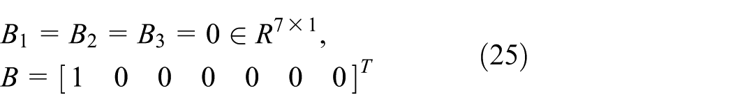
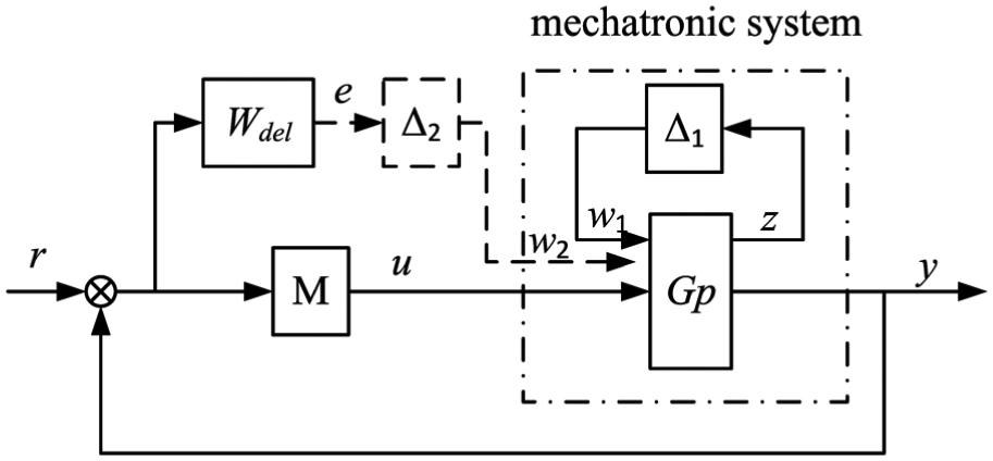
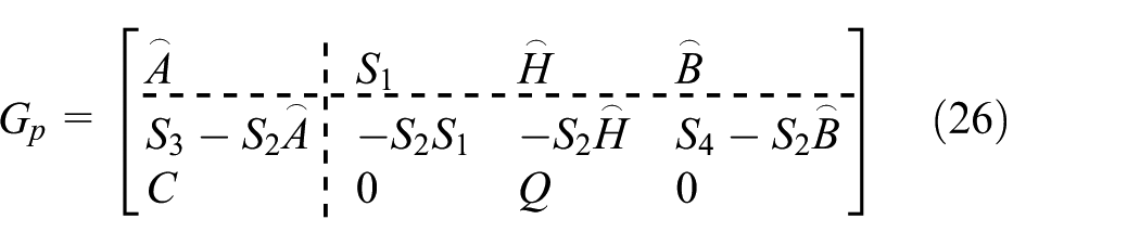
The control goal is to design a feedback controller that stabilizes the closed-loop system and keeps the servo errors and the feedback control actions within required bounds. The dynamics of the precision transmission system strongly depend upon the motion status at any moment. Thus, the controller must be robust against these dynamic changes. As shown in Figure 5, the motion control system performing the precision transmission servo-control mainly consists of the nominal dynamic model (
Robust synthesis block diagram.
In Figure 5, the model in the dotted-line box can be easily transformed by model (15). The nominal dynamic model
where
According to the dimension of the input and output of the precision transmission system,

Note that the feedback connection in Figure 5 is internally stable only if

The system performance weighting function

Control system evaluation
To verify the effectiveness of the controller, we carried out experiments comparing the performance of the proposed controller in this article with a friction compensation controller. The structure of experiment device is shown in Figure 6.

Experimental schematic representation of the precision servo transmission system.
As shown in Figure 7, the friction compensation is based on the identified friction model in section “Parameter identification”; the controller in closed-loop is PID controller. In the experiments, payload disturbance exists which proportional to the angle of the fork-lever; the maximum payload is present in Table 1.
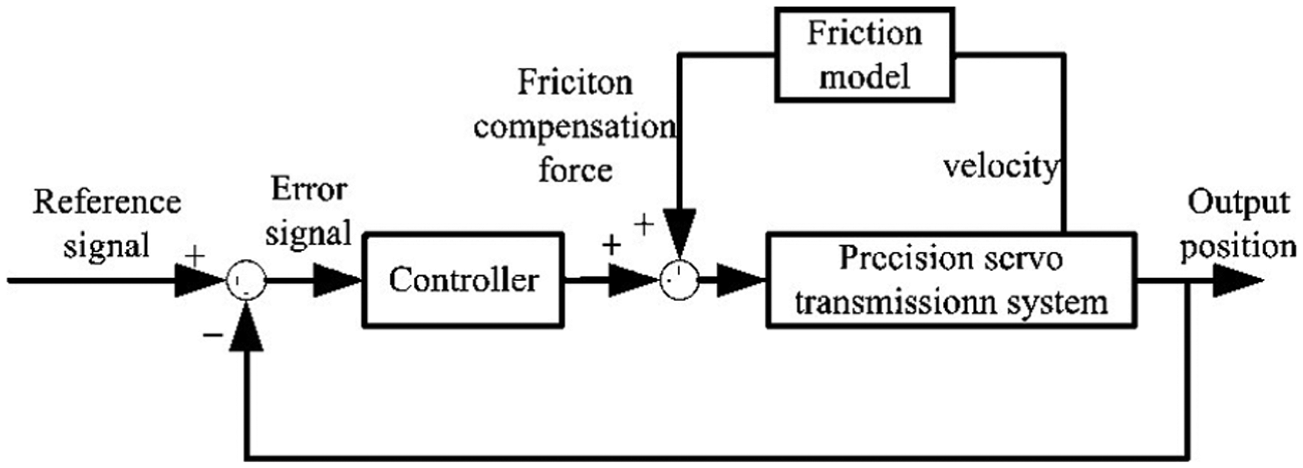
Schematic representation of the friction compensation controller.
In the experiments, the sampling frequency is 1000 Hz. The sinusoidal wave signal is used as excitation signal. Figure 8 plots the experimental results for the friction compensation controller and the proposed robust controller.
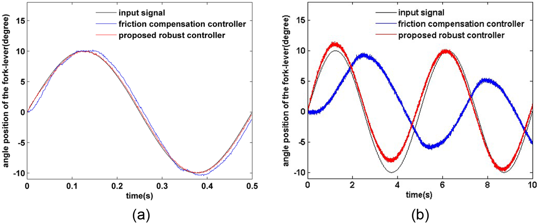
Experimental tracking performance: (a) at low frequencies (2 Hz) and (b) at high frequencies (20 Hz).
The friction of the systems caused the flat-topped phenomenon in control performance. In Figure 4, flat-topped phenomenon is clearly shown by amplitude errors of 0.18°. The backlash causes tracking delay phenomenon, which is shown by blue line in Figure 8(b).
In Figure 8(a), a sinusoidal input signal with 2 Hz frequency and 10°amplitude is given; good tracking performance can be achieved with both controllers. The tracking errors caused by friction and backlash, as shown in Figure 4, are well compensated by the two controllers. The trajectory of the friction compensation controller, shown by red line in the figure, has amplitude overshoot at the peaks and troughs of sinusoidal signal, especially in the troughs. The trajectory of our proposed robust controller in this article have no amplitude overshoot at the peaks and troughs. And the phase lag of the proposed controller is 1.76° which is smaller than the 5.67° phase lag of the friction compensation controller.
In Figure 8(b), a sinusoidal input signal with 20 Hz frequency and 10°amplitude is given. The decrease in amplitude of the friction compensation controller is approximately 50%, and the phase lag is 121.7°. There is a large tracking error using friction compensation controller for high-frequency signals. This is because the friction compensation controller is only for a fixed friction model. Our proposed controller has good agreement with the input signal in amplitude, and the phase lag is only 4.5°.
The frequency characteristics of precision transmission system are shown in Figure 9; one adopt the friction compensation controller and another adopt the proposed robust controller. The two blue lines and two black lines are the frequency domain characteristics when using the proposed robust controller. The one-frequency domain characteristics are obtained using 1° amplitude sinusoidal excitation signal series, and the another frequency domain characteristics are obtained using 10° amplitude sinusoidal excitation signal series. This phenomenon of change in frequency characteristics also implies that the precision servo transmission system is a nonlinear system, which is different from the linear system. The two black lines are the frequency domain characteristics when using friction compensation controller, also using 1° and 10° amplitude sinusoidal excitation signals. The −3 dB bandwidth is extended from 186.6 rad/s by adopting the friction compensation controller to 631 rad/s by adopting the proposed robust controller, using 1° amplitude sinusoidal excitation signal series under the same conditions. And the bandwidth is extended from 109.6 rad/s by adopting the friction compensation controller to 485.1 rad/s by adopting the proposed robust controller, using 10° amplitude sinusoidal excitation signal series under the same conditions. The phase lags both have been greatly improved. From Figure 9, the proposed robust controller is better than the friction compensation controller.

Frequency characteristics of precision transmission systems.
As mentioned above, because of the compensation for friction, the friction compensation controller has good performance in low frequency, but cannot resist the change of gap and payload in high frequency. Apparently, the proposed controller is much better than the friction compensation controller for the precision transmission system, not only can resist the friction effects at low frequencies but also can resist the change of gap and payload in high frequencies. The robustness and effectiveness of the proposed controller can be clearly seen.
Conclusion
In this article, a multi-state dynamic model which is used for control design is presented, and a controller design method using perturbation separation of the dynamic model parameters is introduced. The effects of the dynamic performance variables of the mechanical system, the motor dynamic properties, the nonlinear characteristics of friction, and backlash on the accuracy of motion were discussed. A dynamic model for a typical precision transmission system was established. Identification of model parameters based on experimental analyses was presented. Experimental results demonstrated that the proposed dynamic model was accurate and effective.
A robust controller was also designed for the dynamic model. Closed-loop control experimental using the proposed robust controller compared with friction compensation controller was carried out. Experimental results show that our proposed robust controller can be achieved by the good tracking performance and greatly improves the tracking accuracy in time domain, especially for high-frequency signal tracking. Compared with friction compensation controller frequency response experimental results, the bandwidth and phase lags both have been greatly improved in frequency domain by adopting the proposed robust controller. The proposed framework for integrated design from dynamic modeling to controller design is verified to be feasible and correct.
In this article, the dynamic modeling and controller design are synthesized in a unified form. The proposed method can be modeled for discontinuous vary system. In the process of modeling, the motor and motion state, the mechanical contact state, and the friction state are considered. Through the proposed integrated design process, every model parameters that affect the control performance were analyzed clearly. The proposed method can be used to complex electromechanical system with friction and backlash.
Footnotes
Academic Editor: Nasim Ullah
Declaration of conflicting interests
The author(s) declared no potential conflicts of interest with respect to the research, authorship, and/or publication of this article.
Funding
The author(s) disclosed receipt of the following financial support for the research, authorship, and/or publication of this article: This study was supported by the Scientific Research Funds of the Educational Commission of Hubei Province (grant no. Q20151519), the Natural Science Foundation of Hubei Province, China (grant no. 2014CFB322), and the Fundamental Research Funds for the Central Universities of China (grant no. 2016PY017, 2013QC007).