
Abstract
This article presents a discrete mathematical model for fan blades and theoretically analyses the mathematical relationship between the location and depth of crack and fan blade natural frequency. On the basis of the blade mathematical model, using the theoretical computed natural frequency as the fault feature, this article proposes a fast and efficient fan blade crack fault diagnosis method. Transfer matrix method is used to calculate the first three-order blade natural frequencies under different crack cases and then to build the database in MATLAB. Subsequently, the damaged blade can be detected using changes in natural frequencies by solving the reverse problem. The experimental result shows that this discrete mathematical model can get the exact solution of natural frequency, and the method has certain application value.
Introduction
Because of its stable air pressure, high efficiency, and low noise, fan is extensively applied to factories, mine wells, tunnels, cooling towers, ships, and buildings, where it fulfills it role of ventilation, dust removal, and cooling, thus providing basic assurance of production safety. Of critical importance are fan quality as well as its operation safety and stability. Blades being critical parts in a fan, their performance quality has a direct impact on the efficiency and stability of this machine. Crack is one of the commonest blade faults and endangers the safety of a working fan. How to predict online and real-time blade crack faults using a simple while accurate method has been a challenge troubling both foreign and Chinese engineering and academic communities of equipment fault diagnosis. Existing fault diagnosis methods are roughly divided into two categories: methods based on expert system and variation of vibration characteristics.
Artificial intelligence (AI) techniques, such as fuzzy logic, genetic algorithms (GAs), and artificial neural network (ANN), are utilized to detect fault as well. AJ Oberholster and PS Heyns 1 used ANN for monitoring the online condition of axial-flow fan blades, and the fault features extracted from 24 kinds of different damage levels of the crack blade are used to train the neural network. They showed that the vibration signals obtained from two sensors can effectively diagnose the extent of the crack development without quantitative analysis. M Mehrjoo et al. 2 used the GAs to search the solution of an inverse problem in which the cracks’ location and depth are calculated. It is shown that this method is able to identify various crack configurations in a cracked beam. Combination of two or more intelligent techniques3–6 allows one to overcome the limitations of individual techniques and achieve better performance by utilizing capabilities of each individual classifier.
Intelligent identification method requires a lot of training samples for accuracy, but the crack damage of large axial fan blades is not easy to be fabricated, which brings about the problem of insufficient fault samples. Besides, the selection criteria of the best training algorithm of the fastest rate of convergence for some of the “black box” techniques have not been addressed appropriately, which resulted in an uncertainty on the training speed optimization related to the type and quantity of the training sample.
Another category of existing methods includes those based on examination of changes in natural frequencies, mode shapes, or mode shape curvatures.7–9 Y Wang et al.
9
used mode shape difference curvature to detect the crack location based on finite element method (FEM) and aerodynamic loads’ calculation. Their method has been proved efficiently through the experiment on a wind turbine blade and simulation on a multi-layer composite material blade. But the curvature of mode shape of the damaged blade is too tiny
During the last few decades, intense research on the detection of crack using the changes in frequency has been carried out by researchers.10–13 They noted that any localized damage would affect each mode differently as the existing of the crack in a structure causes a change in its stiffness. Consequently, there would also be a change in the dynamic response of the structure and then the change in frequencies related to crack location and depth has been used to evaluate the state of crack through an inverse processing 14 used soft spring to simulate the boundary conditions of a cantilever beam with a single crack. XF Yang et al. 15 detected the crack of a beam based on an energy numerical model which had been regarded as a continuous model with varying moment of inertia. Most of the current approaches take the cracked structure as a continuous model which is hard to achieve the exact solution with complex boundary conditions, and this kind of method is unable to show the impact of the crack depth and location on blade natural frequency directly.
Therefore, this article presents a discrete mathematical model of cracked blade, which can be more intuitive to see the impact of crack depth and location on blade natural frequency. The aim of this study is to provide a fast and efficient fan blade crack fault diagnosis method. The cracked blade first three-order natural frequency under different crack depth and location is calculated by transfer matrix method based on the theory model presented in this article. And then, using the natural frequency as fault feature, crack depth and location are detected. The accuracy of the proposed mathematical model and the validity of the diagnosis method will be verified by experiments.
Methodology
Crack existing in a structure causes a change in its stiffness and, consequently, could also affect its natural frequency. In order to find out the natural frequency, modal analysis should be carried out for the structure.
Intact fan blade modal analysis
Since the root of the blade is fixedly mounted on the impeller, the blade can be seen as a rectangular cross-section cantilever. Taking a certain type of fan blade as the research subject, this article ignores the effect of damping. The blades were 500-mm long, 180-mm wide, and 1.5-mm thick, which can be regarded as an Euler–Bernoulli beam. The structure diagram of blade is shown in Figure 1.

Diagrammatic sketch of the fan blade.
According to the motion equation and the basic theories of the mechanics of materials, the nth natural frequency

where
Damage fan blade modal analysis
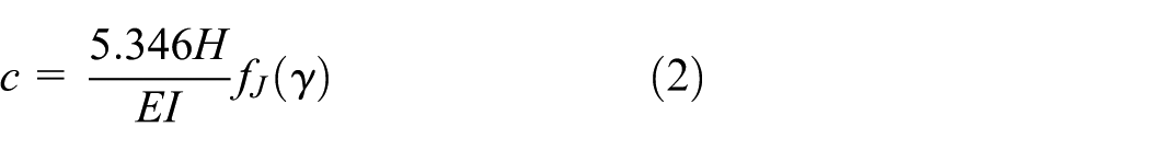
The equivalent stiffness or equivalent flexibility is used to reflect the effect of cracks. Pandey et al. 8 analyzed that the additional flexibility of single crack on blade can be achieved as follows
where
It can be seen from the above equation that the additional flexibility c of single crack is only related to crack depth α while the blade width is constant.
When there is a crack in the blade, the boundary conditions of the blade become very complex. It is difficult to work out exact solutions of natural frequency while regarding the blade as a continuous model. In this article, a discrete mathematical model has been proposed to work out the natural frequency of the blade using the transfer matrix method. Taking into account when the blade is cracked, the angle of rotation around the crack will change evidently, thus the natural frequency can be calculated by investigating the angle of rotation.
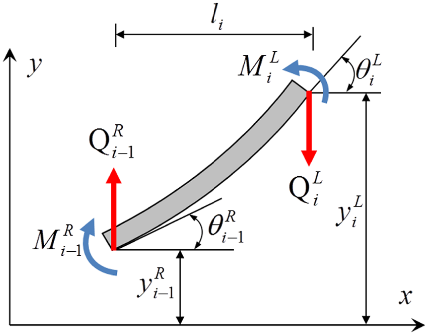
Specifically, the entire blade structure which being regarded as a cantilever was discretized by a number of quality units as shown in Figure 2.
16
Each unit includes a massless beam segment and a centralized quality. In order to study the influence of crack on the whole blade, each unit has four state variables which consists of:

Diagrammatic sketch of the ith unit.
It is assumed that the crack exists in the ith centralized quality. First, stress analysis of the ith massless beam segment has been performed as shown in Figure 3.
Stress analysis figure of the ith massless beam segment.
It is supposed that
According to the basic theories of the mechanics of materials and the equilibrium condition of the ith massless beam segment, the transfer matrix

When the crack is located at the section of the ith centralized quality

where c is the additional flexibility and M is the bending moment of the crack section.

Stress analysis of the centralized quality
The equilibrium condition of the ith centralized quality
where
Thus, the transfer matrix

The whole blade diagrammatic sketch is shown in Figure 5, and the transfer matrix of mathematical model of the whole crack blade can be defined as

where

Diagrammatic sketch of the whole blade.
Then, the relation between the blade tip and the blade root can be expressed as follows

According to the blade boundary conditions, in which

Because of the

which can solve the value of
Through the above analysis, it is not difficult to find when there is a crack on the blade, the natural frequency (for a particular mode) will be affected only by the crack depth and location. Consequently, any crack frequency can be represented by a governing equation

Diagnosis method
As stated earlier, both the crack location and the crack depth influence the changes in the natural frequencies of a cracked blade. Consequently, a particular frequency could correspond to different soundness levels of the blades. On this basis, a contour line, which resulting from a combination of different crack depths and crack locations (for a particular mode) could be plotted in a curve with crack location and crack depth as its axes. The point of intersection of different contour lines indicates the crack location and depth.
To identify the presence of crack in the blade, this article proposes a diagnosis method consisting of three steps: production of fault samples, building of fault sample database, and diagnosis of fault.
To begin, the first three orders of natural frequencies of the fan blades under different crack conditions are found using a theoretical mathematical model and are later used as fault features.
Then, a sample database is built by the use of MATLAB, with the crack location, the crack depth, and the natural frequency of the blade as x, y, and z axis, respectively. Fitted curves are used to build a fault sample database that includes fault samples representing different soundness levels of the blades, hence getting the solution surfaces corresponding to the first three orders of natural frequencies of the blades.
Finally, the measured natural frequency of the to-be-diagnosed blade is input into the fault sample database for fault diagnosis, in the process of which the depth and location of the crack are determined. The section on theoretical analysis makes it clear that the natural frequency of the blade may be treated as a function value having as independent variables the crack depth and location, which may therefore be determined inversely from the natural frequency of the blade. In MATLAB, with the aid of contouring method, the first three orders of natural frequencies of the to-be-diagnosed blade are input into the fault sample database corresponding to each order and three curves are generated. Natural frequency contours corresponding to each order are plotted in the same coordinate system, the depth and location of the crack being determined directly from the points of intersection of the three curves.
Experiment and discussion
A test is conducted to study constant cross-section blades of a certain fan model. The blades are 500-mm long, 180-mm wide, and 1.5-mm thick and their density and modulus of elasticity are 7930 kg/m2 and 190 GPa, respectively. The test system is composed of a constant rectangular cross-section blade, acceleration sensor, a hammer, and a data acquisition and analysis system, as shown in Figure 6. The test include 10 samples, sample 1 is a sound blade, samples 2–9 are blades with different crack conditions, and sample 10 is the cracked test blade. Blade cracks, 1-mm wide, are made using laser cutting technique.

Arrangement diagram of experimental system.
Four acceleration sensors were arrayed symmetrically on the blade, as shown in Figure 7. The force signals were wired into the first channel of the acquisition system; the four acceleration signals were wired into the second, third, fourth, and fifth channel one after another. A rubber head hammer was employed to impact the test piece in the process of natural frequency determination. The data acquisition and processing system INV3020C was used and acquisition is made at a frequency of 12.8 kHz. Taking into account the weight of four sensors, before the start of the experiment, ANSYS Workbench was used to compare the value of natural frequency of the test piece with and without sensors placed on it. Simulation result shows that when the test piece thickness is not less than 1.5 mm, the influence of four sensors on natural frequency of the test piece is around

Arrangement diagram of sensors.
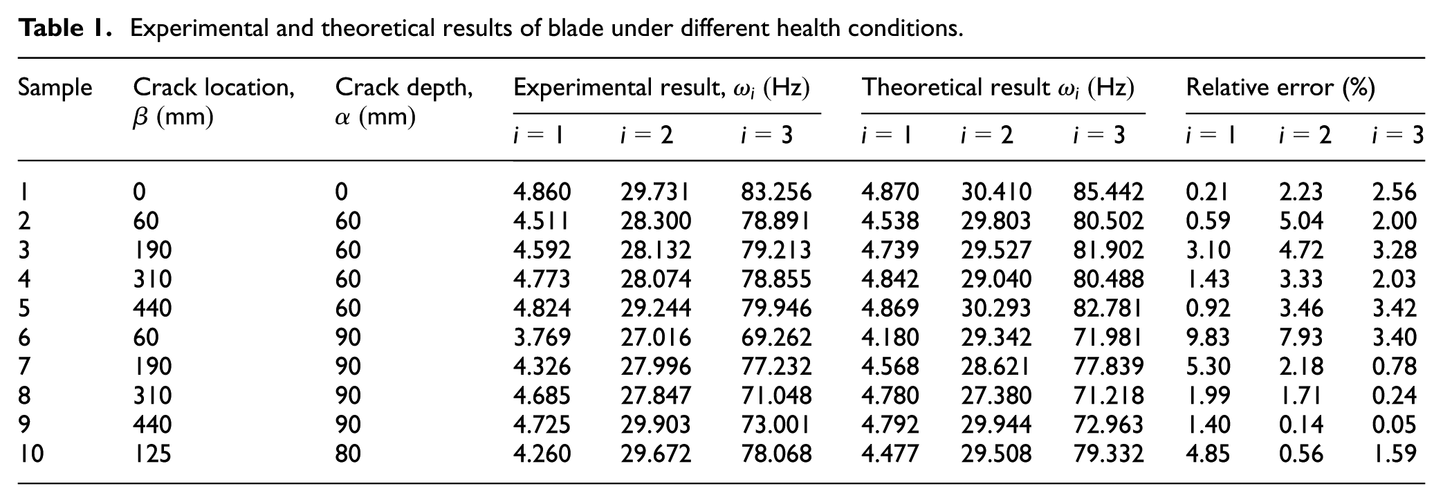
Table 1 summarizes the first three orders of natural frequencies, obtained by theoretical computation and hammering test, of the blade of every crack condition. Table 1 shows small errors between the theoretical computation results and the hammering test results of the first three orders of natural frequencies of the blades. As shown in Figure 8, a solution surface is constructed, by means of fitting technique, for every natural frequency from the theoretically found natural frequencies.
Experimental and theoretical results of blade under different health conditions.
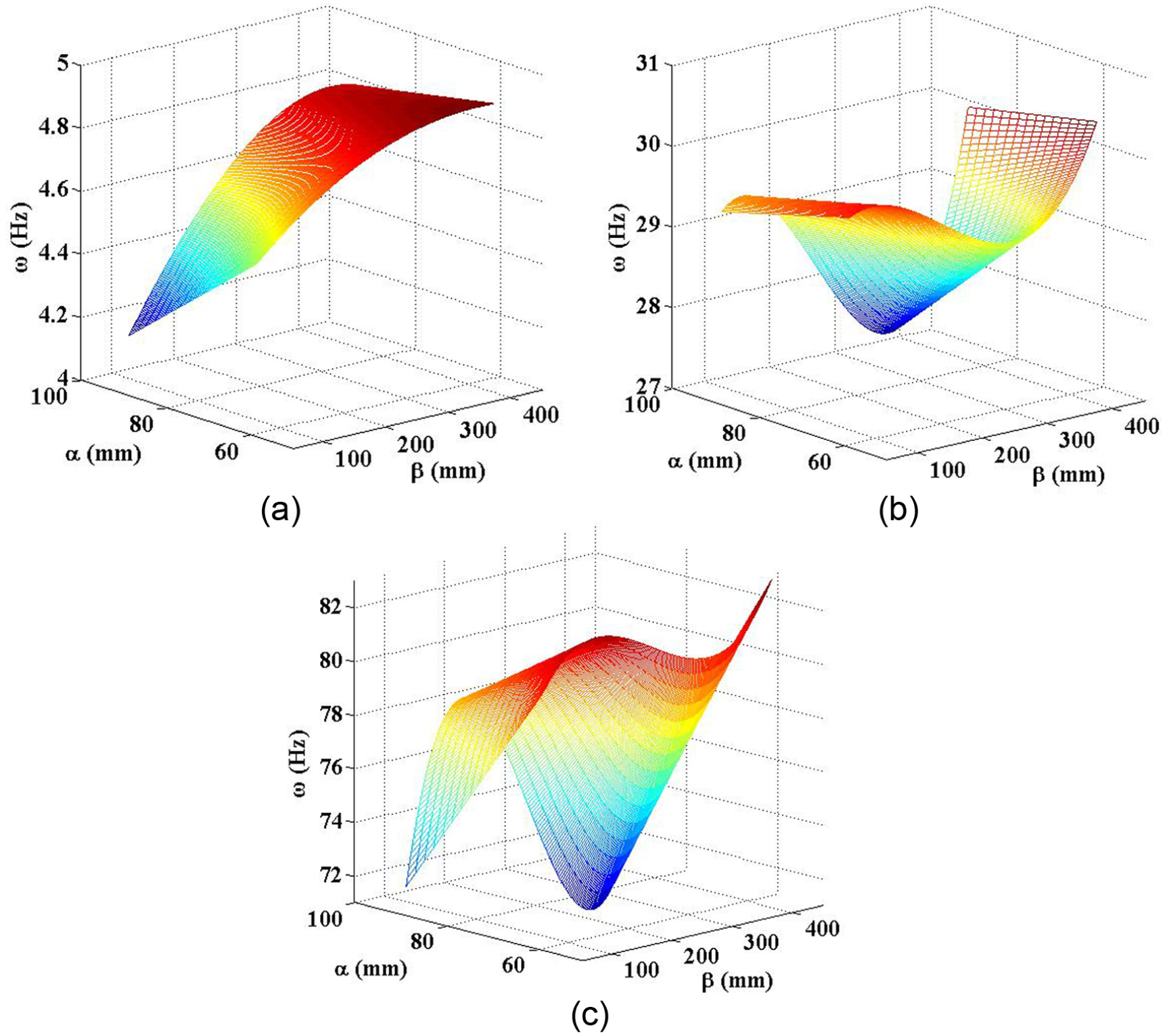
Three-dimensional plots of frequency versus crack location and depth: (a) mode 1, (b) mode 2, and (c) mode 3.
The test is verified in this manner: the test piece being the blade with a crack at β = 125 mm, α = 80 mm, and the first three orders of natural frequencies (see Table 1) found by the theoretical method are input into MATLAB, in which the crack location and depth are determined using contouring method. The three contours are plotted in the same coordinate system, as illustrated in Figure 9. The coordinates of the points of intersection are the location and depth of the crack.

Crack identification technique using frequency contours of the first 3 modes (1: mode 1; 2: mode 2; 3: mode 3).
It becomes apparent that the mathematical model suggested in this article provides an accurate tool for computing the natural frequency of cracked blades and, by solving the inverse problem of natural frequency, also for determining the location and depth of the crack, hence a dependable diagnosis of the crack fault becomes possible.
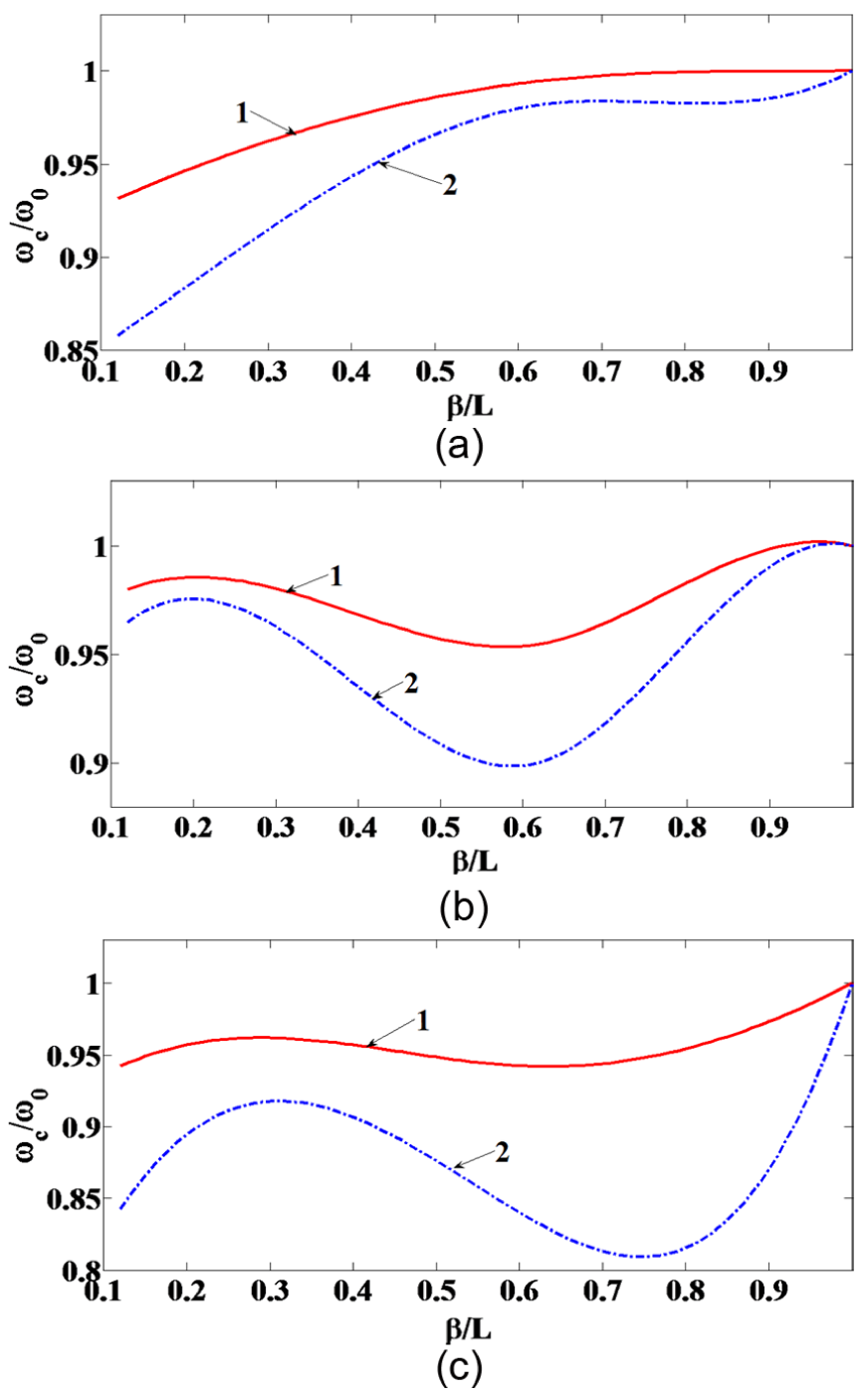
Figure 10 gives the natural frequency versus crack depth relation curves corresponding to various crack locations; Figure 11 presents the natural frequency versus crack location relation curves corresponding to various crack depths, where the natural frequency ratio is the ratio of the natural frequency of a cracked blade to that of a sound blade.

Natural frequencies of various modes in terms of crack depth ratio
Natural frequencies of various modes in terms of crack location ratio
Figures 10 and 11 suggest the following:
The presence of cracks diminishes the natural frequency of a structure;
For each order of modal, the natural frequency of a cracked blade decreases with an increasing crack depth;
The location of crack has a complicated influence on the natural frequency: in the case of the first-order modal, the natural frequency of a cracked blade decreases with a diminishing distance between the crack and the blade root; in the case of the second- and third-order modals, the natural frequency variation depends on the node location of the mode of vibration corresponding to these two orders.
Conclusion
This article proposes a discrete mathematical model of cracked blade and uses transfer matrix technique to evaluate its natural frequency. Small errors being found when the computed results are compared with hammering test results, the solution of an inverse problem is able to determine accurately the depth and location of the crack. Relative to traditional methods, the one described in this article is not limited by the quantity of fault samples in its diagnosis of the accurate crack depth and location and provides a solution with a high efficiency and a low cost. It may be applied to future online diagnosis of crack faults in fan blades.
Footnotes
Academic Editor: Hamid Reza Shaker
Declaration of conflicting interests
The author(s) declared no potential conflicts of interest with respect to the research, authorship, and/or publication of this article.
Funding
The author(s) received no financial support for the research, authorship, and/or publication of this article.