
Abstract
A method for improving the accuracy of a parallel manipulator with full-circle rotation is systematically investigated in this work via kinematic analysis, error modeling, sensitivity analysis, and tolerance allocation. First, a kinematic analysis of the mechanism is made using the space vector chain method. Using the results as a basis, an error model is formulated considering the main error sources. Position and orientation error-mapping models are established by mathematical transformation of the parallelogram structure characteristics. Second, a sensitivity analysis is performed on the geometric error sources. A global sensitivity evaluation index is proposed to evaluate the contribution of the geometric errors to the accuracy of the end-effector. The analysis results provide a theoretical basis for the allocation of tolerances to the parts of the mechanical design. Finally, based on the results of the sensitivity analysis, the design of the tolerances can be solved as a nonlinearly constrained optimization problem. A genetic algorithm is applied to carry out the allocation of the manufacturing tolerances of the parts. Accordingly, the tolerance ranges for nine kinds of geometrical error sources are obtained. The achievements made in this work can also be applied to other similar parallel mechanisms with full-circle rotation to improve error modeling and design accuracy.
Keywords
Introduction
The industrialization of high-speed parallel robots can be greatly promoted by improving their accuracy. As the foundation of accuracy problems, error modeling can provide a theoretical basis for accurate design and kinematic calibration by establishing the mapping relationship between the pose errors in the end-effector and the geometric error sources of the mechanism.
In recent years, a number of error models for parallel manipulators have been established. The matrix perturbation method based on Denavit–Hartenberg (D-H) homogeneous transformation is a classical approach for error modeling.1,2 Yao et al. 3 applied the matrix differential method to establish a static position and orientation error model and analyzed their contributions to the pose error of end-effector for a wheeled train uncoupling robot with 4 degrees of freedom (DOF). And the input motion planning method is adopted to improve the position and orientation accuracy. Wang et al. 4 established an error model for a redundant hybrid robot, which had the ability to account for static error sources. However, this method has the problem that the parameters become discontinuous when the adjacent axes are parallel. Thus, many modified approaches have been proposed. Judd 5 introduced additional parameters into the parallel axis problem and established a modified four-parameter model. However, the corresponding D-H error representation is ill-conditioned when the adjacent axes are vertical. Zhuang et al. 6 proposed a complete and parametrically continuous model, which is able to avoid mutation of the parameters. Besides this, they pointed out that the change in pose is very small as a result of a change in the parameters. Subsequently, the parameters are guaranteed to be complete and continuous.
Differential geometry is another powerful tool for modeling errors in parallel manipulators. Tao et al. 7 established a kinematic model for robot manipulators using a “product of exponentials” (POE) approach. This has the advantage of avoiding parameter discontinuity and also simplifies the calibration process somewhat. Using Lie groups and Lie algebra, Chen et al. 8 established an error model for a serial robot with 6 DOF according to the transformation principles of Lie algebra. They then integrated the links’ geometric errors and the joints’ offset errors together using the quotient manifold of the Lie group so that all errors could be identified simultaneously.
Recently, “screw theory” has been widely applied to error modeling. Zhao et al. 9 applied screw theory to a 2-DOF mechanism and simulated a 5-axis blade milling machine. They also applied their method to evaluate the physical effects of the geometric error sources. Coincidentally, Frisoli et al. 10 adopted screw theory to determine the position accuracy of parallel manipulators under the influence of joint clearances. They applied the method to two 3-DOF translational manipulators and computed the angular- and linear-positioning accuracy. Kumaraswamy et al. 11 adopted screw theory to analyze the kinematic accuracy of mechanisms with varying link lengths and joint clearances and demonstrated that it can be applied conveniently for closed- or open-loop serial manipulators.
As these matrix methods often involve a large number of matrix differential operations, the vector chain method (based on first-order perturbation theory) is widely used. Briot and Bonev 12 developed a kinematic error model for a parallel robot to analyze the maximum orientation and position output errors. Cheng et al. 13 established a pose error model of a symmetrical parallel robot and obtained a statistical model for the sensitivity coefficients. Although the above approaches are widely used for error models, they cannot separate compensatable and uncompensatable error sources. As the pose error of lower-mobility parallel manipulators cannot be compensated, 14 these approaches are not suitable for such manipulators. Bearing this in mind, Huang et al., 15 taking a 3-DOF parallel kinematic machine with parallelogram struts as an example, proposed a modeling method to separate the geometric error sources which affect the position and orientation errors in the end-effector. Using the homogeneous transformation matrix method and screw theory, Liu et al. 16 proposed a general and systematic error model method which allowed the error sources affecting the compensatable and uncompensatable pose accuracy of a platform to be identified in an explicit manner.
Accuracy analysis is a powerful method of mitigating uncompensatable error. For a 6-DOF parallel mechanism, Patel and Ehmann 17 proposed an error model that divides the error sources into those affecting leg lengths and those affecting joint positions. Then, the tolerance allocations of the parts were studied with the aid of a sensitivity analysis. Wang and Ehmann 18 presented first- and second-order error models for a 6-DOF Stewart platform. By means of a sensitivity analysis, the contribution of each error component to the total position and orientation error of the mechanism was thus determined. Kim and Choi 19 proposed an “error range” method, which established a relationship between the pose error of the end-effector and the pose errors of the joint. This was then used to instruct tolerance allocation. Soon et al. 20 constructed an error-mapping model for a Hexapod based on the vector chain method. In this work, a sensitivity analysis was again applied to analyze the errors. Together with the aid of an experiment that measured errors, this work’s results suggest that the pose error is equal to the mean value of each error source. Chen et al. 21 established an error model for a novel “selective compliance assembly robot arm” parallel robot with parallelogram structures. The model was able to reflect the process of error transmission in detail and show the influence of each geometric error on the pose error of the moving platform via a sensitivity analysis. Maurine and Domber 22 proposed an error-mapping model for a mechanism with characteristic parallelogram structures and used the result of a sensitivity analysis to estimate the pose accuracy of the end-effector. Although the above approaches are widely used in accuracy analyses, they cannot filter out the effect of uncompensatable error sources on pose accuracy. For a translational parallel mechanism with parallelogram struts under constraint, Huang and colleagues23,24 considered that the relative and coplanar errors of the parallelogram have a uncompensatable effect on the pose of the end-effector. In order to reduce these two kinds of errors, they subsequently proposed an assembly process which was effectively able to suppress the pose error of the end-effector.
The above achievements constitute important steps in improving error modeling and design accuracy of parallel mechanisms. However, they are mainly focused on planar parallel mechanisms and ordinary spatial parallel mechanisms. In addition, they do not propose a comprehensive and universally applicable method of integrating error analysis and accuracy design into lower-mobility parallel mechanisms. This article considers a novel parallel manipulator with full-circle rotation. The novel manipulator enables kinematic analysis, error modeling, sensitivity analysis, and tolerance allocation to be integrated into a comprehensive framework. Therefore, the work presented addresses the disadvantages of the methods in the literature discussed above by separating pose errors, determining the influence of each error on the pose accuracy of the end-effector, and reducing the uncompensatable error. The method provides tolerance ranges for the uncompensatable error sources which are required in the manufacturing and assembling stages with the aid of a sensitivity analysis.
The work of this article is organized as follows. Section “Kinematic analysis” describes the manipulator system and presents an inverse kinematics analysis, which provides the foundation for the rest of the work. Section “Error-mapping model and error separation” establishes an error model for the manipulator based on the vector chain method. Then, the position and orientation error sources that affect the accuracy in the end-effector are effectively separated by application of a mathematical transformation with parallelogram structure characteristics. Section “Sensitivity analysis” adopts a global sensitivity evaluation index to carry out a sensitivity analysis of all the error sources. The law governing the effect of the geometric parameter errors on the accuracy in the end-effector is proposed, which lays the foundation for the subsequent work on accuracy design. Section “Tolerance allocation” performs tolerance allocation using a genetic algorithm (GA), which provides fundamental guidelines for component manufacture and assembly. Section “Conclusion” presents the conclusions of this article.
Kinematic analysis
System description
The object considered in this study is shown in Figure 1. The parallel manipulator with full-circle rotation,25,26 which has two translational and one rotational (2T1R) DOF, consists of a fixed frame, servo motors, three branched chains, and a moving platform. In the first and second chains, the active links are connected to their servo motors by a transmission mechanism, but in the third chain, the active link is directly connected to the servo motor. One end of each passive link is connected to its active link by a spherical joint, while the end side is connected to the moving platform. A parallelogram structure is employed in each passive link. To ensure the follow-up characteristic, the passive link of the third chain is fixed using three tie rods that are equal in length to a rod that contains the revolute joints on both sides. The third chain can realize two-dimensional translations on the

Solid model of the parallel manipulator with full-circle rotation.
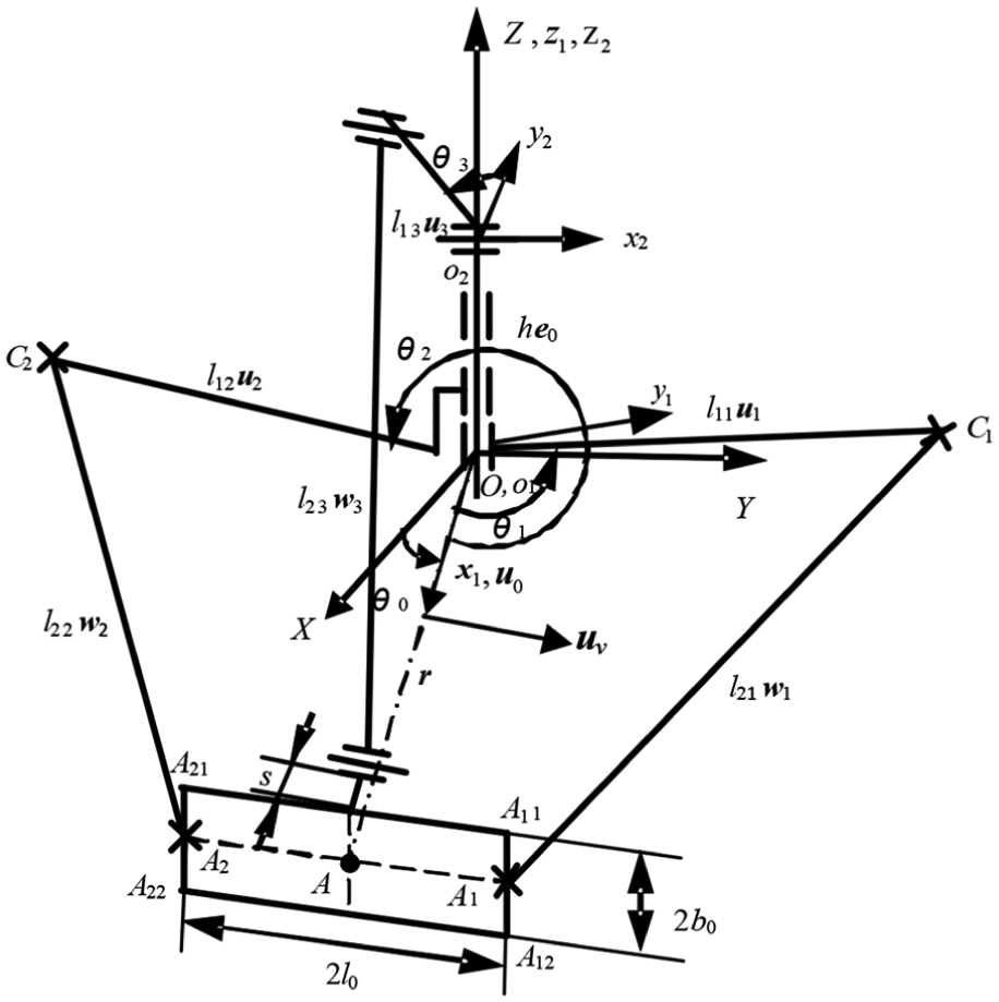
Schematic diagram of the parallel manipulator.
A schematic diagram of the parallel manipulator with full-circle rotation is shown in Figure 2. We take the coaxial hinge point of active links 1 and 2 as the origin O and their coaxial rotation axis as the Z-axis. As the manipulator can realize full-circle rotation, the X- and Y-axes can be selected randomly following the right-hand rule. A fixed coordinate system
Inverse kinematic analysis
Inverse kinematic analysis
27
is considered to determine the active link position angle
Inverse kinematic analysis of chains 1 and 2
As chains 1 and 2 have the same structure and form of motion, we can consider them together. In the moving coordinate system
In the fixed reference coordinate system, the closed-loop vector equation of chains 1 and 2 can be written as

where
The vector
Taking the modulus of both sides of equation (1) gives

where


According to the assembly mode, inverse position analysis gives

Accordingly,

Inverse kinematic analysis of chain 3
Here, we establish a reference coordinate system
Next, we define the vector

where
The following trigonometric expression is obtained by taking the modulus of both sides of equation (5)

where

Considering the assembly mode gives the solution

Thus,

Note that
Error-mapping model and error separation
Description of the coordinate systems and error analysis
There are some structural similarities between the parallel manipulator with full-circle rotation and existing parallel manipulators with parallelogram strut structures. 28 Therefore, the following coordinate systems for the parallel manipulator with full-circle rotation can be defined (see Figure 3):

Coordinate system of chain i (i = 1, 2, 3): (a) Coordinate system of chain 1; (b) Coordinate system of chain 2 and (c) Coordinate system of chain 3.
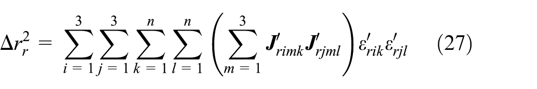
The errors can be described as follows. In chain i, the theoretical value of
Error-mapping model
According to the definitions of the coordinate systems and the description of the geometric error sources, in the kinematic chain

Considering the first-order linear perturbations on both sides of the above equation, we have


where


Let


It can be seen that the position and orientation errors in the parallel manipulator with full-circle rotation are coupled. Note that the orientation errors cannot be compensated for as the parallel manipulator with full-circle rotation only has three controllable DOFs (associated with one translation and two rotations of the platform). Therefore, it is necessary to separate the orientation and position error sources which affect the accuracy in the end-effector from the sources of pose error. In order to achieve the requirement of accuracy in the end-effect, an accuracy analysis and kinematic calibration should be made of the different error sources.
Error separation
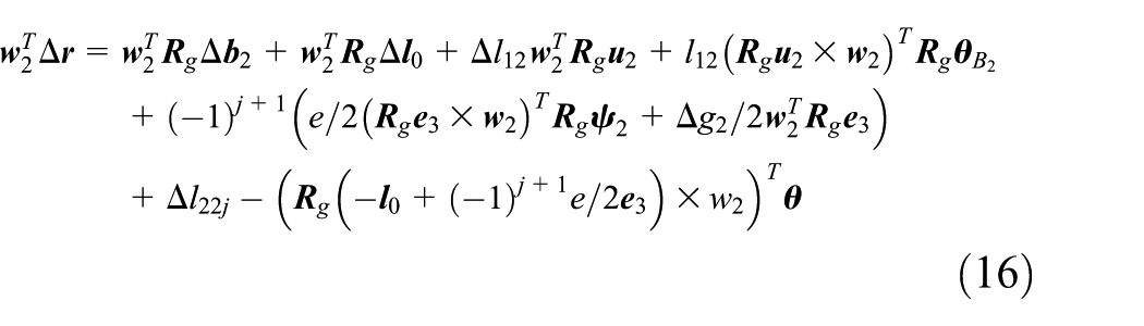
Taking the difference between the two closed-loop equations for chains 1, 2, and 3 yields


where
Rewriting equations (18)–(20) in matrix form leads to the orientation error-mapping function


where


It is clear that there are three kinds of geometrical error sources affecting the pose accuracy of the end-effector. These include the relative length errors
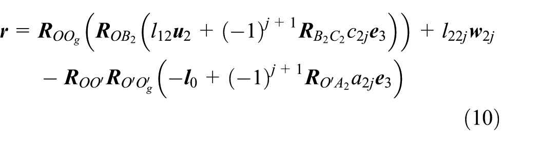
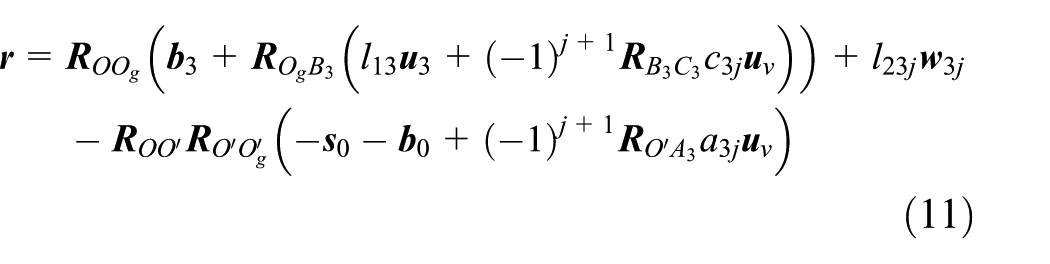
Additionally, the two closed-loop equations belonging to each chain give


where
Rewriting equations (22)–(24) in matrix form gives the position error-mapping function

where


Therefore, the geometrical error parameters affecting the position accuracy of the end-effector can be described as: the mean value of the length errors of two passive links of the parallelogram
Sensitivity analysis
Sensitivity analyses can guide tolerance design and assembly of every part by evaluating the degree of influence of the geometrical errors on the orientation accuracy of every part of the structure. Using a sensitivity analysis, the laws governing the effects of geometric parameter errors on the orientation error of this manipulator (with full-circle rotation) can be proposed.
Consider the position error-mapping model

Taking the norm of both sides of equation (26) yields
where
We assume that all elements in
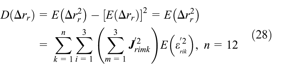
For the new manipulator with full-circle rotation, the geometrical errors of the same type in each chain share the same variance, that is

Thus, the standard deviation of

For the orientation error
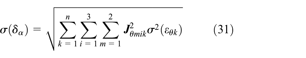
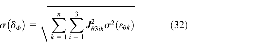
Similarly, the sensitivity coefficients of the orientation error with respect to geometric error


These sensitivity coefficients represent the standard deviations of the errors in the end-effector caused by a unit standard deviation of geometrical error. As sensitivity coefficients vary with the configuration of the mechanism, their mean values can be employed as a sensitivity evaluation index in the overall prescribed workspace. The index can be defined as
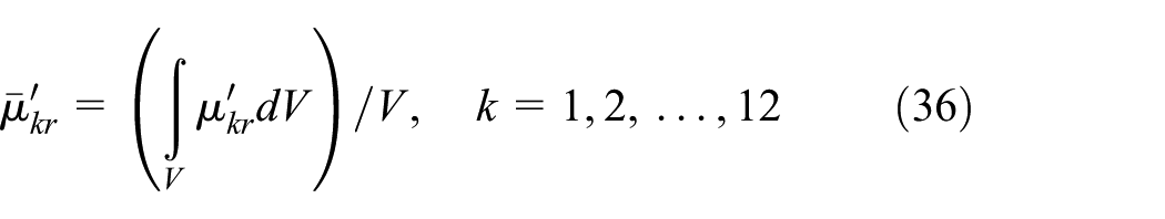
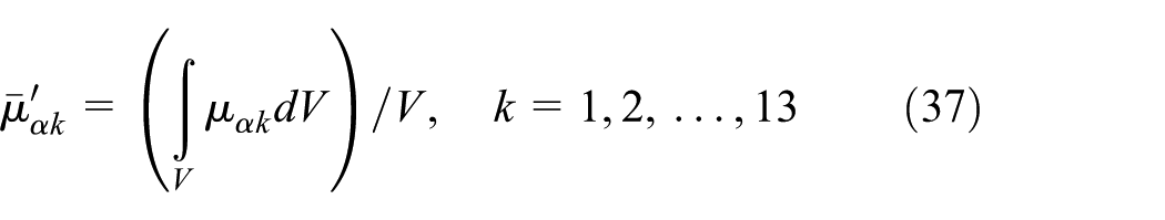

where V is the volume of the prescribed workspace.
Note that this parallel manipulator can realize full-circle rotation and has the same performance in all directions. As shown in Figure 4, the reachable workspace of reference point on moving platform is the intersection of three subspaces associated with three kinematic chains. The subspace of each chain is the region encircled by three surfaces whose circle center is

Cross-section of the workspace of the parallel manipulator with full-circle rotation (through the yz plane): (a) Geometric parameters in task workspace and (b) Sectional view of reachable and task workspace.
Thus, the three global sensitivity evaluation indices above can be measured in the prescribed working area in the yz plane, that is


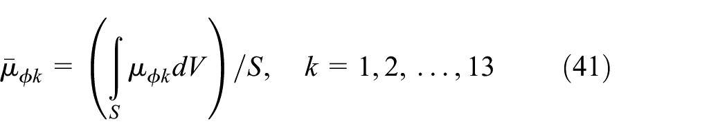
A sensitivity analysis can be carried out on the parallel manipulator with full-circle rotation by utilizing the indices given in equations (39) - (41). The nominal dimensions used in the analysis are shown in Table 1. According to the working and force-transfer characteristics of the mechanism, the prescribed workspace is a cylindrical ring with an inner radius of 300 mm, outer radius 650 mm, and height 200 mm. In the yz plane, it is a rectangle, 300 mm away from the central axis, with a length of 350 mm and width of 200 mm (as shown in Figure 4).
Nominal dimensions of the parallel manipulator with full-circle rotation (the linear unit is mm).

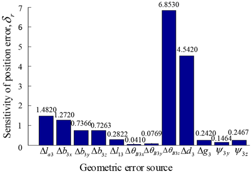
Figures 5–8 show the results of global sensitivity analyses of the pose and volumetric errors

Sensitivity analysis of the geometric errors with respect to error in the verticality of the spindle axis about the xy plane
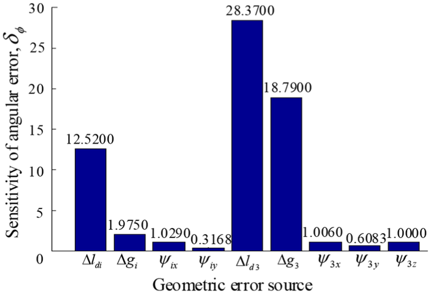
Sensitivity analysis of the geometric errors with respect to the angular error in the z-axis

Sensitivity analysis of the geometric error with respect to position error in chain
Sensitivity analysis of the geometric error with respect to position error in chain 3.
Tolerance allocation
For the parallel mechanism with less freedom, the uncompensatable error sources cannot be compensated for by kinematic calibration. In order to guarantee the accuracy in the position and pose of the mechanism, the manufacturing tolerances of the parts need to be suitably allocated via tolerance optimization. There are nine kinds of geometric error sources for the parallel manipulator with full-circle rotation. In order to reduce the manufacturing cost, the tolerance of the geometric parameters should be relaxed as far as possible subject to the premise that the tolerances of the orientation errors

where
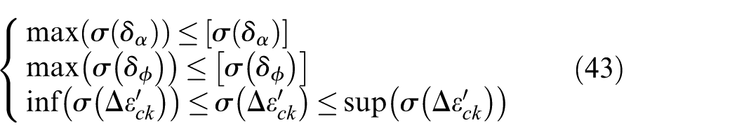
where
This is a complicated optimization problem, one which we tackle using a GA. GA is an evolutionary algorithm. It is based on imitating the mechanism of genetic selection that occurs in nature to find the optimal solution.
GA includes three basic operators: selection, crossover, and mutation. First, the algorithm searches for a set of approximate optimal values among all the possible values, which then form the genetic population. Then, it screens for satisfactory individuals among the genetic group to form a new population. In the screening process, new individuals are continuously produced by crossover and mutation. Finally, a set of satisfactory optimal values are obtained. Iteration is the main numerical process used to solve this nonlinear optimization problem. However, iterative methods in general can easily fall into local minima which may trap them, and as a result, the phenomenon referred to as “death cycle” is observed. GA is capable of overcoming this shortcoming. As a consequence, a GA is better placed to find the global minimum error. Moreover, compared with other optimization methods, GA that has small population sizes and high mutation rates can rapidly find a good solution.
In this work, the solution process is directly performed using the GA toolbox built into the MATLAB software application. The minimum value of the objective function is the fitness function, which is determined by equation (39). The constraint conditions are determined using equation (40). Table 2 shows the allowable parameter values wherein the standard deviations are determined as per JB/T 10792.1-2007. 29
Allowable parameter values.

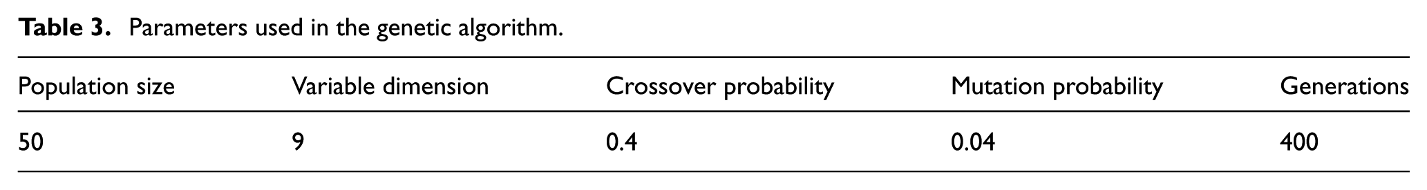
Parameters needed to implement the GA include variable dimensions, number of generations, population size, mutation probability, and crossover probability. In this case, the variables are nine kinds of uncompensatable error sources and so the variable dimension is 9. The number of generations is taken to be 400, which can produce good calculated values and is relatively fast. Figure 9 shows the optimization process when the population size is set to 20 and 80, both of which have bad convergences. Using a large population size has the advantage of improving the search quality of the GA and prevents convergence before maturation. However, it also increases the number of calculations involved and reduces the rate of convergence.
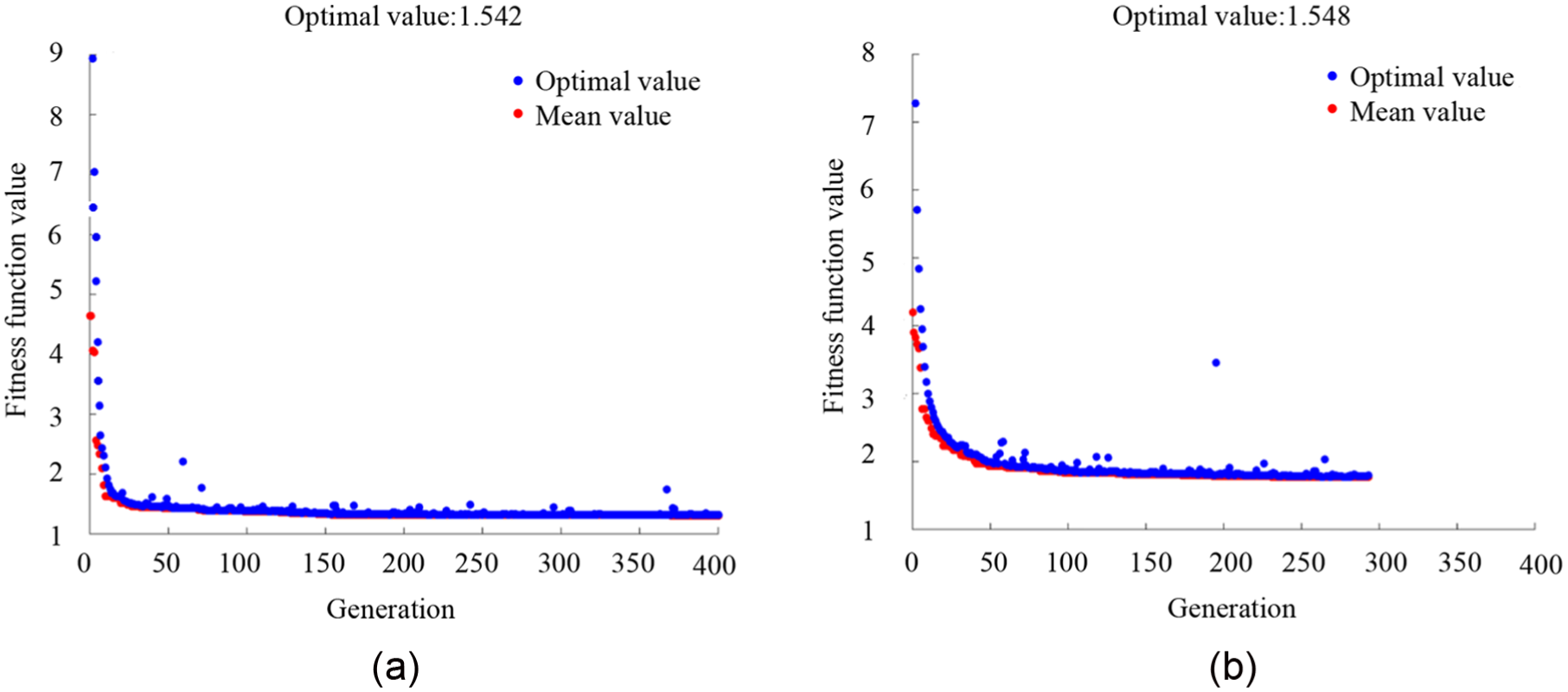
Optimization of the fitness function with different population sizes: (a) population size is 20 and (b) population size is 80.
Figure 10 shows the optimization processes when the crossover probability is set to 0.05 and 0.99. When the crossover probability is large, the introduction of a new structure is more likely. However, it also results in randomization. A low crossover probability may make the genetic search stagnate.

Optimization of the fitness function with different crossover probabilities: (a) crossover probability is 0.05 and (b) crossover probability is 0.99.
Figure 11 shows the optimization processes when the mutation probability is set to 0.001 and 0.08. Mutation probability is an important factor that keeps the population diverse. A low mutation probability may easily generate a local extreme value, but too a high mutation probability can make the genetic search too random. Mutation probability affects the ability of the algorithm to search locally, whereas the crossover probability affects the ability of the algorithm to search globally. So, they need to be coordinated with each other in an appropriate manner.

Optimization of the fitness function with different mutation probabilities: (a) mutation probability is 0.001 and (b) mutation probability is 0.08.
The selection of the parameters discussed above is dependent on the type of problem involved. Therefore, in any actual problem, one needs to change these parameters continuously in order to obtain the best results according to certain requirements. The above selection process is appropriate in special situations. Actually, in the current situation, many simulations have been done that suggest the best values to use. The final parameter values assumed are shown in Table 3. The values of the fitness function subsequently obtained using the GA are shown in Figure 12.
Parameters used in the genetic algorithm.

Optimization of the fitness function.
Based on the
Optimization results for the tolerances of the sources of uncompensatable error.

A photograph of a prototype parallel manipulator with full-circle rotation is shown in Figure 13. According to our measurements, it can achieve
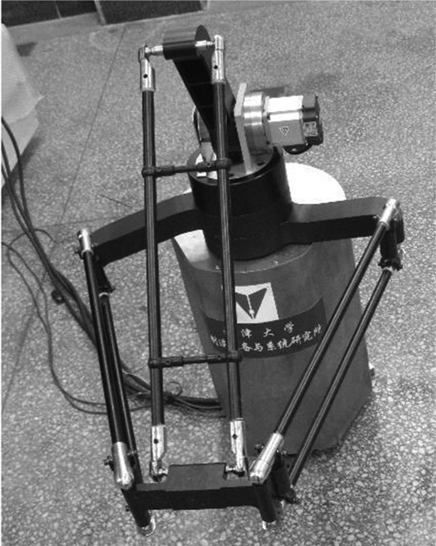
Prototype of a parallel manipulator with full-circle rotation.
Conclusion
A unified error model for a novel 3-DOF parallel manipulator with full-circle rotation has been formulated. The following conclusions can be drawn:
The error model can be formulated using the method of vector chains. Position and orientation error-mapping models can be established via mathematical transformation of the parallelogram structure characteristics. The orientation and position error sources can then be separated effectively. There are 18 orientation and 36 position error sources. There are some common error sources within the two kinds of error sources, namely,
A global sensitivity evaluation index can be formulated to evaluate all the error sources, and the laws governing the effects of the geometric errors on accuracy in the end-effector can thus be derived. The result indicates that the relative link length errors
Based on the analysis results, the problem of the design accuracy of the mechanism can be converted into a nonlinearly constrained optimization problem. The tolerance allocation of each link can then be optimized using a GA. This provides the information necessary for the manufacture and assembly of each component.
The uncompensatable errors are separated effectively and controlled in the process of manufacturing and assembly. The compensatable errors are compensated by kinematic calibration when the parts achieve the certain accuracy. The method presented in this article is facilitated to the kinematic calibration of the mechanism in the future.
The method of design can be readily extended to other similar low-mobility parallel structures. As low-mobility parallel structures include uncompensatable error sources, the end-effector pose error cannot be totally compensated for using software. The model presented shows how kinematic analysis, error modeling, sensitivity analysis, and tolerance allocation can be successfully integrated into a comprehensive framework to improve the accuracy of low-mobility parallel structures.
Footnotes
Appendix
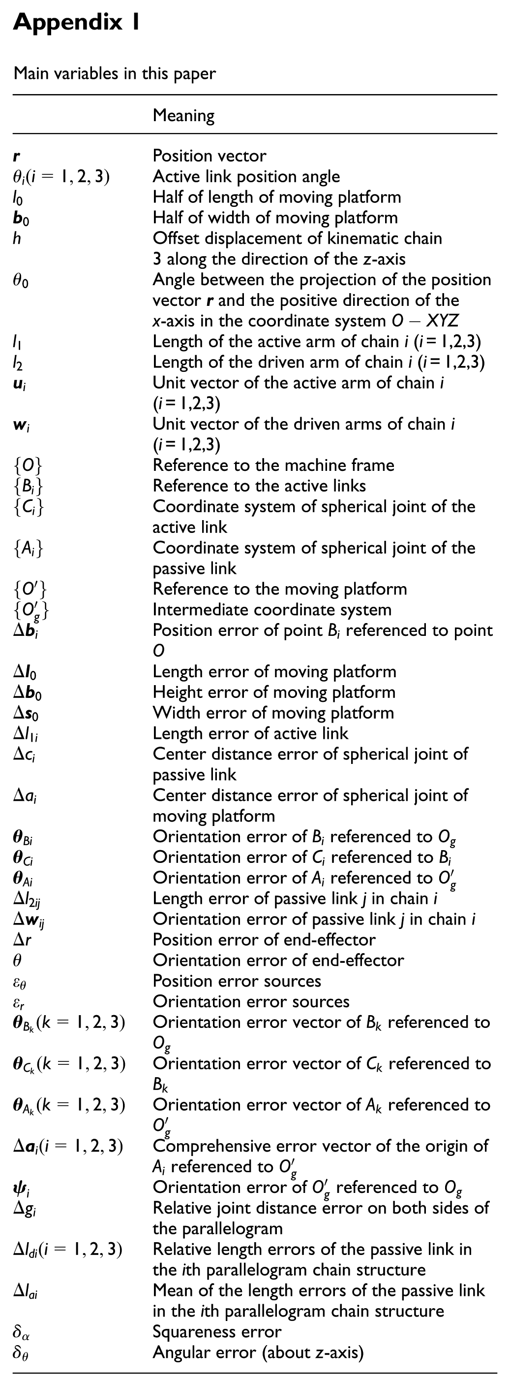
Main variables in this paper
| Meaning | |
|---|---|
|
|
Position vector |
| Active link position angle | |
| Half of length of moving platform | |
| Half of width of moving platform | |
| h | Offset displacement of kinematic chain 3 along the direction of the z-axis |
| Angle between the projection of the position vector |
|
| Length of the active arm of chain i (i = 1,2,3) | |
| Length of the driven arm of chain i (i = 1,2,3) | |
| Unit vector of the active arm of chain i (i = 1,2,3) | |
| Unit vector of the driven arms of chain i (i = 1,2,3) | |
| Reference to the machine frame | |
| Reference to the active links | |
| Coordinate system of spherical joint of the active link | |
| Coordinate system of spherical joint of the passive link | |
| Reference to the moving platform | |
| Intermediate coordinate system | |
| Position error of point referenced to point O | |
| Length error of moving platform | |
| Height error of moving platform | |
| Width error of moving platform | |
| Length error of active link | |
| Center distance error of spherical joint of passive link | |
| Center distance error of spherical joint of moving platform | |
| Orientation error of referenced to | |
| Orientation error of referenced to | |
| Orientation error of referenced to | |
| Length error of passive link j in chain i | |
| Orientation error of passive link j in chain i | |
| Position error of end-effector | |
| Orientation error of end-effector | |
| Position error sources | |
| Orientation error sources | |
| Orientation error vector of referenced to | |
| Orientation error vector of referenced to | |
| Orientation error vector of referenced to | |
| Comprehensive error vector of the origin of referenced to | |
| Orientation error of referenced to | |
| Relative joint distance error on both sides of the parallelogram | |
| Relative length errors of the passive link in the ith parallelogram chain structure | |
| Mean of the length errors of the passive link in the ith parallelogram chain structure | |
| Squareness error | |
| Angular error (about z-axis) |
Academic Editor: Jose Ramon Serrano
Declaration of conflicting interests
The author(s) declared no potential conflicts of interest with respect to the research, authorship, and/or publication of this article.
Funding
The author(s) disclosed receipt of the following financial support for the research, authorship, and/or publication of this article: This research were supported by the National Natural Science Foundation of China (grant no. 51575385) and the Natural Science Foundation of Tianjin (grant no. 16JCZDJC38400).