
Abstract
Three-point bending is one of the most common methods of studying the mechanical performance of materials. The influence of punch radius in the measurements is not considered in the previous studies. This article focuses on the influence of the punch radius on the elastic modulus. The experiment is set up to measure the elastic modulus of 6061 aluminum alloy (6061 Al) and copper as the specimens, in which several different radii of punches are used. The maximum bending deflection of the middle point is 1.0 mm. Moreover, a finite element simulation is constructed to simulate the bending process of specimen, which is consistent with the experimental results. According to the results, the punch radius has affected the measurement of elastic modulus, and the elastic modulus, the contact length, and the peak load increase with the increase in the punch radius. Combining the experiment result (E1) and the standard result (E3) of Changchun research institute for testing machines, it is found that the appropriate punch radius is in the range from 2.5 to 3.0 mm for this experiment, when the specimen’s dimension is 30.0 mm × 6.0 mm × 1.0 mm.
Introduction
It is well known that three-point bending (TPB) test is one of the most common material testing methods to study the mechanical performance of materials with structural applications.1–4 TPB is often applied to determination of brittleness of low-plasticity materials, such as cast iron, high carbon steel, and ceramics. In the application, the bending strength5,6 and deflection 7 are obtained during the bending. In addition, TPB is also used to check the quality of the surface of sandwich materials.8,9 The bending strength, bending deflection, and bending fatigue10,11 can be obtained by the TPB. In recent years, the finite element analysis (FEA) has been widely applied.12–14 A finite element model has been built to analyze the damage initiation and propagation of materials under the test of TPB.13,15
In previous studies, the influence of punch radius on the elastic modulus is rare. We discovered that the radii of punches in TPB test have not been unified. The radii of punches are 10.0, 10 8.0,4,13 5.0, 8 and 1.25 mm. 16 In addition, some radii of the punches are not even mentioned. The biggest punch radius is eight times the smallest one. Gandhi et al. 17 proposed an analytical and empirical model to estimate the top roller position explicitly as a function of desired (final) radius of curvatures for three-roller cylindrical bending of plates, considering the contact point shift at the bottom roller plate interfaces. Gandhi and Raval 18 developed analytical model considering the effect of initial radius, relative residual radius, initial strain, and change of flexural modulus during the deformation. Chudasama and Raval 19 found the bottom roller inclination was smaller. There was less difference in the radii at the roller ends, which suggested less difference in the reaction forces on the roller. These studies do not take into account the influence of punch radii on the TPB tests.
In this article, a finite element model is built to simulate the bending process of specimen with different punch radii of TPB, combining the data with the experiments of the TPB tester. The results have the same changing trend. With the increase in the punch radius, the elastic modulus increases accordingly. In the test of TPB, the values of elastic modulus and peak load increase with the increase in the punch radii, as the maximum bending deflection of the middle point is 1.0 mm.
Theory of TPB
TPB analysis is established based on the following assumptions:
The material of bending is homogeneous throughout the deformation process.
There must be a layer of fiber unchanged in the material, and this layer is called the neutral layer.
There is no interaction between the longitudinal fibers of normal stress, which means all the longitudinal fibers of beam are in simple tension or compression.
The theoretical model of TPB is given in Figure 1. The middle point deformation submits to Hook’s law 20

where σ is the stress (N/mm2), E is the elastic modulus (N/mm2), and ε is the strain. The result of elastic modulus E of TPB is given by the Sun et al. 10 in equation (2)

where l is the span of supports (mm), b is the width of specimen (mm), h is the thickness of specimen (mm), F is the load,
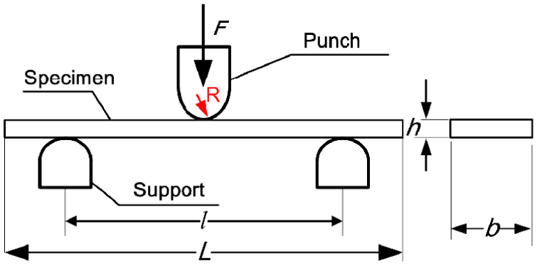
Theoretical model of three-point bending test.
Experiments
Specimens
The specimens are 6061 Al and copper, which are cut by the electric discharge machining, and its dimension is 30.0 mm × 6.0 mm × 1.0 mm. The specimens have been prepared not only by grinding sequentially with waterproof emery paper from 500 to 3000 grit manually but also by polishing with 25-µm SiO2 solution.
TPB test
The TPB experiment system is illustrated in Figure 2, including data acquisition and processing, electrical control, control software, and the TPB tester. The electrical control and control software are employed to control the TPB tester. The computer is in charge of the data acquisition and processing. The TPB tester is used in the experiment that is designed by us, calibrated by the Agilent G200 nanoindenter. The span of supports is 22.0 mm. The motor is Maxon Ecmax DC servo motor, through two-level worm wheel controls speed as shown in Figure 2.

Experimental system of three-point bending test.
In general, the punch radius is equal to the supports’ radius. At the beginning, the radius of punch and supports is 1.0 mm. Then, in turn, the radii of punch and supports are 1.5, 2.0, 2.5, 3.0, and 3.5 mm. Before the experiment, the dimension of specimens is measured and recorded in Tables 1 and 2. Then, the specimens are placed on the supports vertically. The punch is contacted with the center of specimen. The displacement–control load is selected, and the loading rate is 1 µm/s. When the maximum bending deflection of middle point is 1 mm, the test is completed. At room temperature conditions, the test is repeated three times for each of punch radius.
Experimental elastic modulus E1 of 6061 Al with different punch radii.

Experimental elastic modulus E1 of copper with different punch radii.

FEA
In order to verify the correctness of the experimental results, ABAQUS is used to construct the finite element of TPB static-load simulations. The radii of punch and supports are 4.0, 4.5, 5.0, 6.0, 7.0, and 8.0 mm, respectively. Taking into account the experimental loading conditions, the punch, the specimen, and supports are set as ideal elastic plastic bodies. The material of the punch and supports is the same as the experimental T10 tool steel, and its elastic modulus is 210 GPa and Poisson’s ratio is 0.275. The material of the beam is 6061 Al. The elastic modulus, Poisson’s ratio, and the yield strength are 69 GPa, 0.33 MPa, and 55.1 MPa, respectively. These data from the Changchun research institute for testing machines are given as the standard results for 6061 Al. The specimen dimension is 29.95 mm × 5.93 mm × 0.92 mm, and it is the average of the experimental measurements. The span of supports is 22.0 mm. Combining with the experiment, the FEA is divided into two processes of loading and unloading. Loading and unloading steps are controlled by the displacement method, and the maximum deflection of middle point is 1.0 mm. The bending stress and strain of the specimen are simulated using the contact algorithm. The finite element simulation model of TPB is shown in Figure 3.
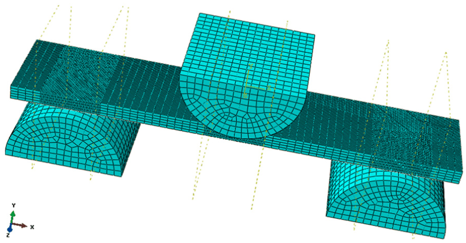
Simulation model of three-point bending.
The specimen is meshed with fully reduced integration elements (C3D8R element type), and the mesh size is 0.5 mm; in addition to the contact area of specimen with the punch and supports, the mesh size is 0.1 mm. The punch and supports are used in ABAQUS Interaction Module although fully reduced integration element type (C3D8R element type) is applied to the punch and supports, and the mesh size is 0.5 mm. Wholly 6 degrees of freedom of the supports’ bottom are fixed. The punch has only 1 degree of freedom, namely, it can only move along the Y-axis. The contact property is set to be the tangential behavior. Friction is considered between the punch and the specimen’s surface, and the frictional coefficient is 0.15. 21 Other settings are chosen by default.
Results
Experiment elastic modulus E1
The load–deflection curves with different punch radii are shown in Figure 4. The peak load increases with the increase in the punch radius. In order to obtain the slope of the load–deflection curves, the load data are selected from 10 to 40 N for linear fitting. The slopes of different punch radii are substituted into equation (2), and the elastic modulus (E1) of 6061 Al and copper is illustrated in Tables 1 and 2, respectively. When the punch radius varies from 1.0 to 2.0 mm, the relative change of elastic modulus is small. However, the relative change of the elastic modulus is larger, when the punch radius changes from 2.0 to 2.5 mm. When the punch radius is 2.5 mm, the standard deviation is the minimum. With the increase in the punch radius, E1 and peak load increase.
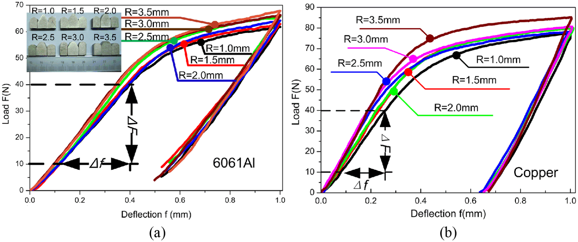
Influence of load–deflection curves with different punch radii on the specimens in the experiments: (a) 6061 Al and (b) copper.
FEA elastic modulus E2
By the FEA, the load–deflection curves of TPB are obtained with the punch radii being 4.0, 4.5, 5.0, 6.0, 7.0, and 8.0 mm. The curves of middle point bending deflection are distributed as shown in Figure 5. With the increase in the punch radius, the peak load also increases. In order to obtain the slope of the curves, the load data between 20 and 140 N that are selected for linear fitting are shown in Figure 5. The slopes of different punch radii are substituted into equation (2), and the elastic modulus (E2) is demonstrated in Table 3. When the punch radius changes from 4.0 to 6.0 mm, E2 has a small relative increase. When the punch radius is 8.0 mm, E2 is the maximum. The elastic modulus increases with the increasing punch radius. It is consistent with the experiment result. The simulation results are demonstrated in Figure 6. With the increase in the punch radius, the stress of the middle point of specimen increases. When the punch radius increases from 4.0 to 8.0 mm, the stress distribution is gradually concentrated on the middle point of specimen.

Load–defection curves of the finite element simulation with different punch radii.
Elastic modulus E2 of FEA with different punch radii.


Simulation results with different punch radii.
Standard elastic modulus E3
In order to verify the experimental result E1, specimens with 6061 Al and copper were tested by the Changchun research institute for testing machines. The experiment model of the Changchun research institute for testing machines is shown in Figure 7. The punch radius is 5.0 mm. The span of supports is 96.0 mm. The elastic moduli of 6061 Al are 68.80, 69.02, and 69.40 GPa. The average is 69.07 GPa, and the standard deviation is 0.19. It is the standard elastic modulus (E3) of 6061 Al. The elastic moduli of copper are 108.47, 108.32, and 108.13 GPa. The average is 108.31 GPa, and the standard deviation is 0.17. It is the standard elastic modulus (E3) of copper.

Experiment model of the Changchun research institute for testing machines.
Discussion
Contract length d
During the bending, because the radius of punch is not unified, the contact length d of the specimen with the punch is different. For example, when the punch radius is 1.0 mm, it is shorter. However, when the radius of punch is 3.5 mm, it is longer, which is shown in Figure 8. The result is consistent with Carbajal and Mujika. 5 When the material is constant, the contact length d is a function of the punch radius and the load force. It is defined by Carbajal and Mujika

where R is the radius of the punch, F is the punch load, and ET1 is the transverse modulus defined as

where

where

where k is a constant. Accordingly, the contact length d increases with the increase in the punch radius.
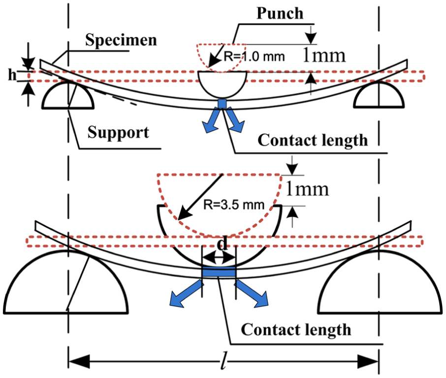
Contact length d with different punch radii effect on the specimens.
After experiment, the specimens are placed under the opto-digital microscope, which tested the area of the punch contact with the surface of specimen. The radius of 1.0-mm punch has a greater damage to the surface of specimen than that of 3.5-mm punch. There are a large number of upheavals and steel pits on the surface of the specimen where the areas contacted with the punch. Furthermore, some materials are pushed out of the surface as shown in Figure 9(a). The depredation is clear and continuous. In order to observe the imprint that has been caused by the radius of 1.0-mm punch, a steel pit is selected and then enlarged so that the upheavals and steel pits could be seen clearly. The upheavals are formed from the materials that are pushed out of the steel pit. The edge of the steel pit is not smooth. However, the surface of specimen did not damage large areas by the radius of 3.5-mm punch. The surface of specimen is smooth. There are only a small number of steel pits, which is shown in Figure 9(b). In order to see the imprint that has been caused by the radius of 3.5-mm punch, a deep steel pit is selected and then enlarged. There are no obvious upheavals at the edge of the steel pit. The edge of steel pit is smoother than the steel pit in Figure 9(a). The steel pit is shallow. Therefore, the effect of the different punch radii on the surface of specimen can be seen clearly using the opto-digital microscope. Therefore, the contact length d is affected by the radius of punch.
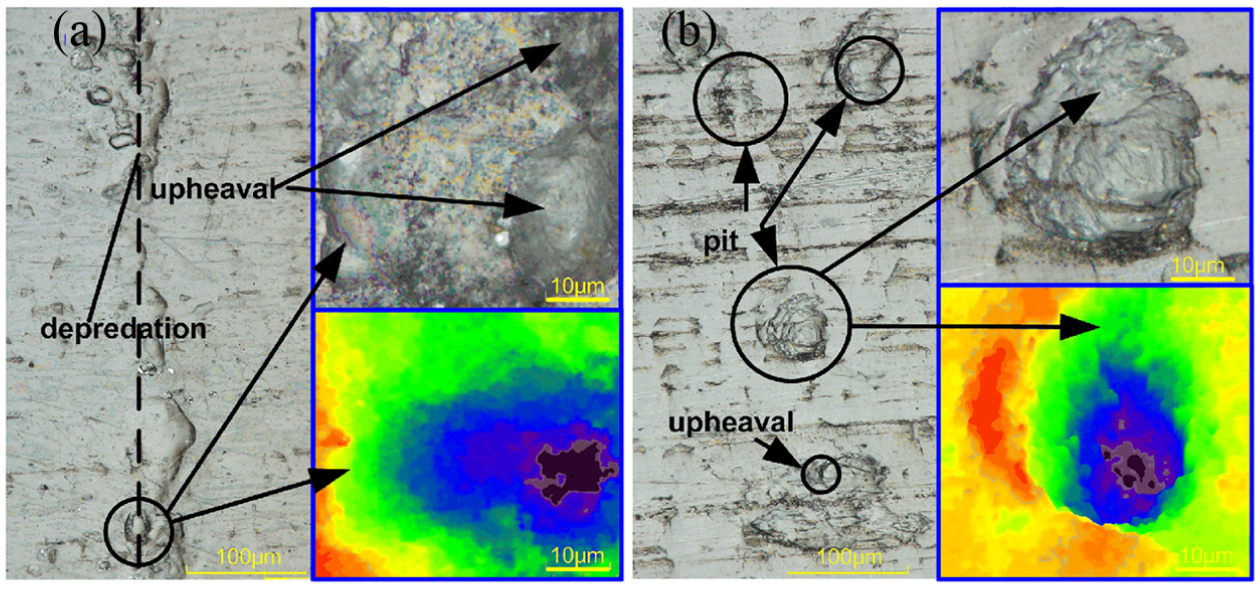
Specimens are tested by the opto-digital microscope after experiment. (a) The 1.0-mm punch damage on the surface of specimen. (b) The 3.5-mm punch damage on the surface of specimen.
Combining the elastic moduli E1, E2, and E3
Comparing the experimental results (E1) of 6061 Al with copper, it is inferred that they have the same trend. The elastic modulus increases with the increasing punch radius. Combining E1 of 6061 Al with the finite element simulation results (E2) of 6061 Al, we found that E1 and E2 have the same changed trend as shown in Figure 10. Undoubtedly, with the increase in the punch radius, the elastic moduli E1 and E2 correspondingly increase. When the punch radius is 4.0 mm, the E2 is much larger than E1. When the punch radius is 2.5 mm, the standard deviation is the smallest. The experimental elastic modulus E1 is consistent with the standard elastic modulus E3 of Changchun research institute for testing machines as shown in Figure 10. Combining the E1 and E3, it is found that the appropriate punch radius is in the range from 2.5 to 3.0 mm in this experiment.
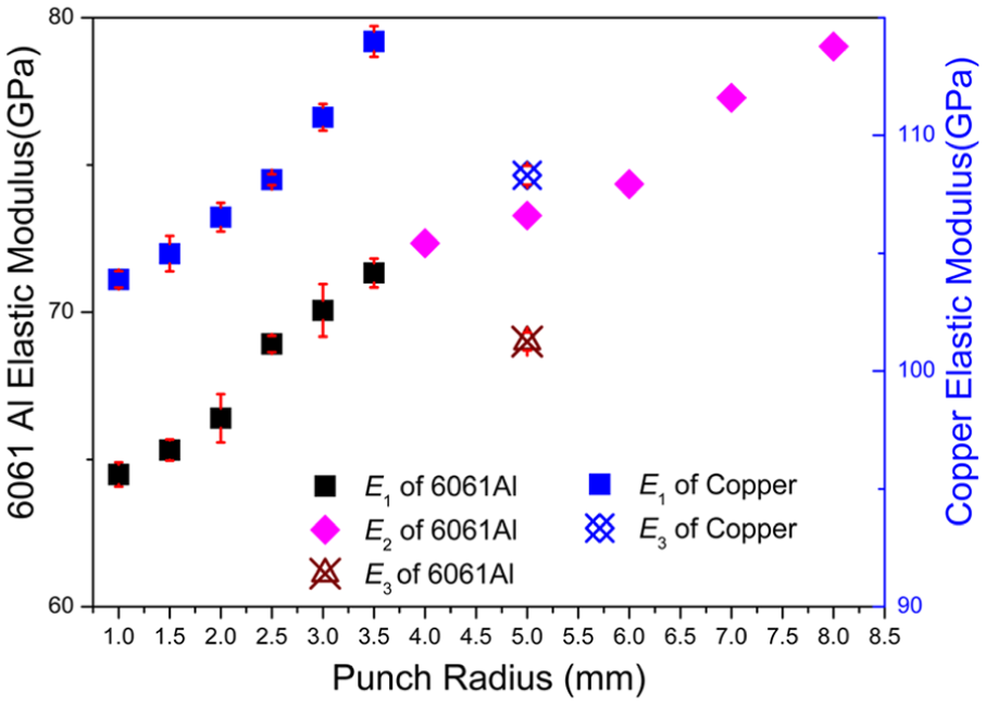
Elastic moduli of E1, E2, and E3 with different punch radii.
Conclusion
In this article, the influence of different radii of punches on the elastic modulus has been investigated by the TPB. The maximum deflection of the middle point is 1.0 mm. The data of the FEA and experiments are analyzed, in which conclusions can be drawn as follows:
With the increase in the punch radius, the elastic modulus, the peak load, and the contact length are also increased.
According to the experiment, the appropriate punch radius is in the range from 2.5 to 3.0 mm. In order to obtain the reliable elastic modulus from the deflection of the specimen, high stiffness in machine, supports, and punch is required.
Footnotes
Academic Editor: Farzad Ebrahimi
Declaration of conflicting interests
The author(s) declared no potential conflicts of interest with respect to the research, authorship, and/or publication of this article.
Funding
The author(s) disclosed receipt of the following financial support for the research, authorship, and/or publication of this article: This research is funded by the National Natural Science Foundation of China (grant no. 51275198), Special Projects for Development of National Major Scientific Instruments and Equipments (grant no. 2012YQ030075), and Program for New Century Excellent Talents in University of Ministry of Education of China (grant no. NCET-12-0238), Specialized Research Fund for the Doctoral Program of Higher Education (grant no. 20130061110026), and Patent Demonstration Project for Research Team in Jilin Province (grant no. 20130416015ZG).