
Abstract
Passive shock absorbers are designed for standard load condition. These give better vibration isolation performance only for the standard load condition. However, if the sprung mass is lesser than the standard mass, comfort and road holding ability is affected. It is demonstrated that sprung mass acceleration increases by 50%, when the vehicle mass varies by 100 kg. In order to obtain consistent damping performance from the shock absorber, it is essential to vary its stiffness and damping properties. In this article, a variable stiffness system is presented, which comprises of two helical springs and a variable fluid damper. Fluid damper intensity is changed in four discrete levels to achieve variable stiffness of the prototype. Numerical simulations have been performed with MATLAB Simscape and Simulink which have been with experimentation on a prototype. Furthermore, the numerical model of the prototype is used in design of real size shock absorber with variable stiffness and damping. Numerical simulation results on the real size model indicate that the peak acceleration will improve by 15% in comparison to the conventional passive solution, without significant deterioration of road holding ability. Arrangement of sensors and actuators for incorporating the system in a vehicle suspension has also been discussed.
Introduction
Passive fluid shock absorber provides simple and effective solution for comfort and handling of the vehicle. These convert vibration energy into heat by throttling viscous fluid through restricted orifice and are widely used in vehicle suspensions. Furthermore, the fluid damper can be tuned by changing the fluid flow area to vary the vibration isolation performance.
Two-degree-of-freedom quarter car model for analysis of a passive suspension is shown in Figure 1. Sprung mass (m1) represents chassis and vehicle body, whereas un-sprung mass (m2) includes suspension and tire. Quarter car model has been used for numerical simulations to evaluate vibration isolation performance of the presented system.

Quarter car model.
Sprung mass acceleration is the criteria used to quantify vehicle comfort performance. 1 Lower sprung mass acceleration gives better comfort and vice versa.
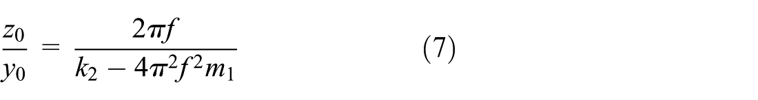
Steady-state response of the sprung mass acceleration for harmonic displacement of the un-sprung mass is given as follows

Damping factor (

where C is the damping coefficient, m1 is the sprung mass, wn is the natural angular velocity, w is the angular velocity of un-sprung mass excitation, ks is the suspension sprung stiffness, r is the frequency ratio (w/wn) and ypk is the peak displacement of the un-sprung mass.
Equation (1) is rewritten to obtain to include the mass and the sprung mass acceleration (steady-state response under harmonic excitations of amplitude ypk) and can also be written as follows

where f is the un-sprung mass excitation frequency.
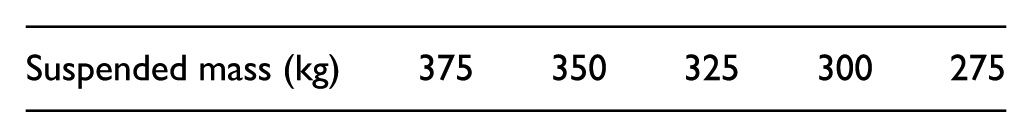
Equation (3) implies that the acceleration will depend on the sprung mass in addition to the excitation frequency. Simulation has been performed with the quarter car model to evaluate the effect of change in the sprung mass on comfort. Input parameters used in the simulations are given in Table 1.
Simulation input parameters.

Acceleration response for different values of sprung mass is plotted in Figure 2. It can be observed from Figure 2 that the passive suspension gives better comfort for maximum sprung mass. However, as the sprung mass reduces, higher acceleration deteriorates vehicle comfort.

Sprung mass acceleration for different values of sprung mass.
Automobiles are designed to support maximum mass by calculating the suspension parameters (namely, stiffness and damping coefficient). However, it can be observed from equation (3) that the passive shock absorber will not give consistent performance as the sprung mass changes.
Variable stiffness and damping have been studied in past to optimise vibration isolation performance. Liu et al. 2 introduced Voigt element comprising of controlled damper and constant spring. The damper offers few discrete damping levels, to achieve eight different control schemes. The authors have validated single-degree-of-freedom model and concluded that equivalent stiffness of the system can be changed by up to four times. Practical implementation of variable damping has been done with magnetorheological (MR) damper. Xu and Ahmadian 3 studied the variable stiffness and damping characteristics of an automobile shock absorber in terms of load transfer at the tires. A simple ON-OFF control strategy has been developed to improve normal force at the tire. Zhang et al. developed variable stiffness damping isolator, based on the MR damper. Spring in the conventional fluid dampers has been replaced by combination of two springs and an adjustable damper to achieve simultaneous control over the system damping and equivalent stiffness. 4
Xu et al.3,5 have implemented variable stiffness and damping suspension with a MR damper to improve lateral stability of the vehicle. ADAMS modelling is used for simulation of an adjustable shock absorber comprising of MR damper and smart air spring. The control strategy is composed of a fuzzy controller and operates with two force levels. Sun et al. 6 have developed a suspension based on MR damper and MR smart air spring. The authors have compared vibration isolation performance of the systems that include variable damping and stiffness, fixed damping with variable stiffness and variable damping with fixed stiffness.
Zhou et al. developed 3-degree-of-freedom quarter car model of the system with adjustable stiffness and damping. MR damper system varied the equivalent stiffness from 5500 to 25,000 N/m in two discrete steps. 7 Variable stiffness mechanism has been developed that changes the shock absorber stiffness by moving upper support point of the shock absorber. 2 Simulations were performed on the quarter car testing with 1:10 scaled down model. MATLAB Simscape mechanism has been used for the theoretical analysis for vibration isolation. Variable stiffness and damping isolator proposed by Wang and Meng 8 have proposed MR damper operating in few discrete levels. Anubi et al. 9 developed a variable stiffness mechanism comprising of a horizontal control strut and a vertical strut. The attachment point between the shock absorber and chassis has been changed with hydraulic actuator to implement active control on the shock absorber stiffness. MR elastomers are used in vehicle seat suspension to achieve improved driver body acceleration response.10,11
Anubi et al. 9 performed simulation and experimentation on a variable stiffness suspension. The performance criteria include car body acceleration and tyre deflection. Deo and Suh 12 used auxiliary air tubes to develop an adjustable suspension. For ‘n’ numbers of auxiliary volumes, the system could achieve ‘2 n ’ stiffness settings. Simulations on a variable stiffness system are performed with ADAMS/CAR software and MATLAB Simulink. Random road analysis indicates that the variable stiffness system performs better than its passive counter parts for comfort and handling. 5
Gervasi 13 patented a variable stiffness mechanism comprising main leaf spring and counter leaf spring with sliding mechanism creating adjustable contact between the two springs. A hydraulic mechanism has been used to set the contact point, to achieve desired stiffness. Variable stiffness system has been developed that comprises of two controllable dampers.2,14 Quarter car simulations on these systems indicate that peak acceleration will reduce to 70% to that of the passive system. Semi-active variable stiffness and damping system proposed by Tan et al. 15 comprise of a mechanism with hydraulic cylinder and piston.
Agarawal 16 presented non-linear control algorithm to vary stiffness and damping in single-and multi-degree-of-freedom system subjected to pulse-type excitation. Variable stiffness has been achieved by combination of spring and adjustable dry friction damper. Liu et al.2,14 performed numerical simulation of variable stiffness and damping system with two controllable dampers. The aforesaid system offers two levels of damping and stiffness each. Liu et al. have performed numerical simulation and experimentation on variable stiffness and damping isolator comprising of MR elastomers. The authors have reported about 36%–50% reduction in displacement transmissibility in comparison to the passive solution.2,14 Gavin and Doke 17 have been studied response time of a control valve mechanism for variable stiffness vibration isolation system with numerical model. Fourier spectrum analysis of an adjustable vibration isolation system indicates about 80% reductions in displacement response in comparison to the passive solution. 18
Xian and Shuen 19 developed a system that can vary the stiffness from 50 to 80 N/mm, to suit applications in construction company. Azadi et al.20,21 have identified cable-driven mechanism based variable stiffness unit for an engine mount. Modified quarter car model is used to perform transmissibility analysis of the system. In another cable-based variable stiffness mechanism used in automotive industry, Azadi et al.20,21 demonstrated stiffness variation from 823 to 1400 N/mm.
Magnetic forces are used to develop two-level variable stiffness device. 22 The authors have reported up to 14% reduction in the relative response. However, when used in automobile suspension, large magnetic force and presence of shock and vibration might limit its application.
Dynamic stiffness of a shock absorber depends on its stiffness, which can be evaluated from the force and displacement matrix. 23 Variable stiffness and damping systems discussed in the literature mostly comprise of adjustable MR dampers that operate with few discrete force levels. Although MR damper provides sophisticated solution, there are few drawbacks of the system. High-performance commercial MR fluids are difficult to settle down under dynamic conditions. 9 Moreover, it provides an expensive solution. Major factors affecting the cost are MR fluids, seals, electromagnets, precision manufacturing, tolerances, sensors for suspension velocity measurement and actuators. Since MR fluids are inherently abrasive, durability of MR dampers is limited. This aspect requires dynamic seal design, material selection and detailed analysis of MR fluid chemistry.
Spelta et al. implemented control strategy for variable stiffness and damping in a vehicle shock absorber. The authors have implemented comfort-oriented strategy that overcomes choice between hard stiffness setting and end stop hitting. 24 Variable stiffness suspension with adjustable attachment point between shock absorber and chassis requires costly sensors and actuators. Moreover, response time of the system may be higher since it involves actuators and hydraulic piston–cylinder arrangement. Coil or leaf spring with adjustable length can be used to develop variable stiffness suspension.25–27 These need large power consumption and the system damping is not controlled with it.
Fluid dampers provide a reliable and economic solution for an automobile suspension. Furthermore, their oil flow characteristics can be tuned to improve the vibration isolation performance over a wide band.
In this article, a variable stiffness and damping shock absorber have been presented. The presented system comprises of fluid dampers with adjustable force level. Control algorithm is established to control the shock absorber stiffness and damping to achieve consistently better performance for any mass supported by the shock absorber. Quarter car model has been evaluated with numerical analysis. Finally, design and analysis of the full-scale system is presented. Applicability is demonstrated with comparison of the numerical simulation results for comfort and handling and the same are compared with that of the fluid shock absorber.
Concept, design and analysis
In this section, conceptual design of the prototype has been discussed along with calculation of the fluid damping force.
Overview of variable suspension system
Variable stiffness and damping suspension system shown in Figure 3(a) is composed of two springs and an adjustable fluid damper. Flow area at the adjustable damper can be varied by changing position of the cover piece, as illustrated in Figure 3(b). There are eight orifice holes in the piston. Position of the cover piece can be changed to vary number of active holes in the piston orifice from 0 to 8. Change in the number of active orifice holes changes damping coefficient ‘C’ of the fluid damper. Variable stiffness has been achieved by changing damping characteristics of the fluid damper.

(a) Overview of proposed system and (b) arrangement to vary damper holes.
Details of the adjustable fluid damper are given as follows:
Diameter of the piston and cylinder: 60 mm;
Diameter of the piston holes: 1.6 mm;
Oil viscosity: 50 cst.
Details of the spring used in the prototype are given as follows:
Spring material: spring steel;
Stiffness of the spring 1 (k1): 13.32 k N/m;
Stiffness of the spring 2 (k2): 32.7 k N/m.
The system acts as two springs connected in parallel with the entire piston holes blocked (i.e. zero active orifice holes), resulting in equivalent stiffness of ‘k1 + k2’. However, as the active number of holes in the piston increases, the adjustable damper offers least damping, which results in the equivalent damping approaching to ‘k1’. Eight different stiffness settings can be achieved with the prototype.
Design considerations
Referring Figure 3(a), ‘m1’ and ‘m2’ are sprung and un-sprung masses, respectively. ‘F’ is the sinusoidal excitation force with amplitude of ‘F0’. Displacement of masses ‘m1’ and ‘m2’ are given by ‘z’ and ‘y’, respectively. Displacement of the point, connecting variable damper and spring 2, is given by ‘zm’.
The equations of motion for the system shown in Figure 3(a) are given as follows


where
When only base excitation is considered (F = 0), ratio of output to input steady-state amplitude is written as follows
When only excitation force ‘F’ is taken (with y = 0), the system equivalent stiffness can be written as follows

Simplifying equation (8), the equivalent stiffness is written as follows

Equation (9) shows that with value of ‘C’ approaching ‘∞’, last two terms of equation (9) becomes zero, resulting in equivalent stiffness of ‘k1 + k2’. Whereas, lower value of ‘C’ results in last two terms of equation (9) to become significant. This will reduce equivalent stiffness to a value lesser than ‘k1 + k2’. It can be observed from the above analysis that the equivalent stiffness can be controlled with variation of ‘C’.
The prototype that has shown in Figure 3(a) gives settings of variable stiffness. Furthermore, it can be added with an adjustable fluid damper connected between sprung and un-sprung mass to design a shock absorber with variable stiffness as well as variable damping. Schematic arrangement in the proposed shock absorber is shown in Figure 4.

Shock absorber with variable stiffness and damping.
Numerical simulations for variable stiffness
In order to illustrate basic performance of a variable stiffness system, simulations have been performed with the 2-degree-of-freedom system shown in Figure 4. Simulation parameters are as follows:

Ratio of sprung mass displacement to excitation force.

Transmissibility for the variable stiffness system.
Simulation results for transmissibility shows that location of peak changes with damping coefficient. Lower damping coefficient gives larger transmissibility in comparison to higher damping intensity. Figure 6 shows the variation of peak displacement amplitude (
For the fluid damper shown in Figure 7, the damper force is given as follows

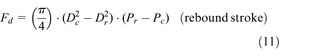
where

Fluid damper in the prototype.
Numerical simulation of the prototype has been performed with MATLAB Simulink and Simscape. Governing differential equations (4) and (5) are used to construct the quarter car model in Simulink. Fluid elements have been modelled in MATLAB Simscape. Relative velocity and displacement from the quarter car Simulink model are used in the Simscape model to calculate the fluid damping force, which is again used in the Simulink model. MATLAB Simscape has custom libraries for fluid elements like orifice values and annular clearances, which gives wider flexibility in simulation. Coupling between the quarter car Simulink and Simscape model is shown in Figure 8.

Coupling between Simulink and Simscape model.
Experimentation
Photograph of the prototype is shown in Figure 9. Four springs (1) with stiffness of 3.33 N/mm each, when connected in parallel, result in stiffness of (3.33 × 4 = 13.32 N/mm). Further another spring (2) with stiffness of 32.77 N/mm and an adjustable damper are connected in series. The damper with details as revealed in Figure 10 has the piston with ϕ 1.6 mm diameter holes. The cover piece unblocks the desired number of holes. The prototype damper can provide four different force levels.
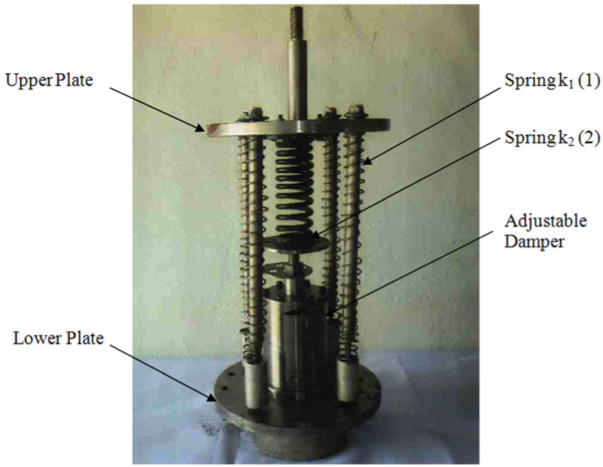
Photograph of the prototype.

Arrangement in the adjustable damper.
Test setup shown in Figure 11 has been used to measure displacement, acceleration and force transmissibility of the device. During experimentation, lower plate is connected to lower reciprocating mass, whereas the upper plate is fastened to the upper reciprocating mass of the test rig. The two reciprocating masses are guided along the support bar, by roller bearings to minimise friction. Lower reciprocating mass is driven by an electric motor (7.5 kW power) through the Scotch Yoke mechanism. Load cells are mounted on the lower mass and below upper mass to measure force transmissibility. Fast Fourier transform (FFT) vibration meter (SVAN-958) is used to record sprung mass displacement and acceleration within the test frequency range.

Test setup.
Vertical velocities during the experimentation are 0.14–0.79 m/s. These are close to medium and low bump velocities of a vehicle shock absorber, which are 0.2–0.4 and 0.4–0.8 m/s, respectively. 1 Measurement range of the load cells is 5 N and above.
Simulation results
Frequency response for the sprung mass acceleration and displacement is computed with numerical simulation and experimentation. The input excitations are harmonic within 1–8 Hz frequency range.
Peak values of the sprung mass displacement are plotted in Figure 12, whereas results for sprung mass acceleration are plotted in Figure 13. Experimental findings follow the similar trend as of the simulation results, which validate the accuracy of the theoretical model. Maximum sprung mass displacement occurs at the resonance frequency and reduces thereafter. Equivalent stiffness (at 6 Hz) is calculated from equation (5) and given in Table 2.

Simulation and experimental results for peak displacement of sprung mass.
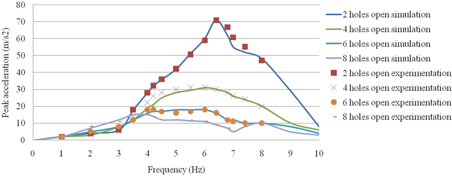
Simulation and experimental results for peak acceleration at the sprung mass.
Equivalent stiffness of the prototype.
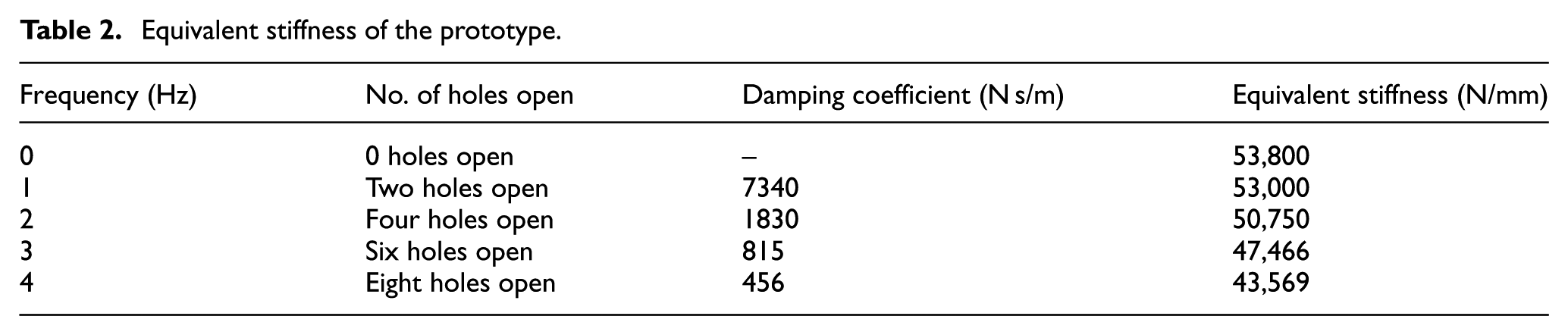
Table 2 shows that the prototype gives stiffness variation up to 33%. Furthermore, the stiffness variation can be increased by changing damping coefficient of the adjustable damper. It can also be observed from Table 2 that as the number of holes in the piston increases, damping coefficient reduces and equivalent stiffness reduces. On the other hand, lower active number of piston holes gives higher damping coefficient and equivalent stiffness.
The presented prototype is being investigated for incorporation in a vehicle suspension, to achieve variable stiffness. However, apart from energy storage, the disclosed system will perform energy dissipation (damping). In design of the real size design, this aspect has been evaluated to design damping intensity of the shock absorber.
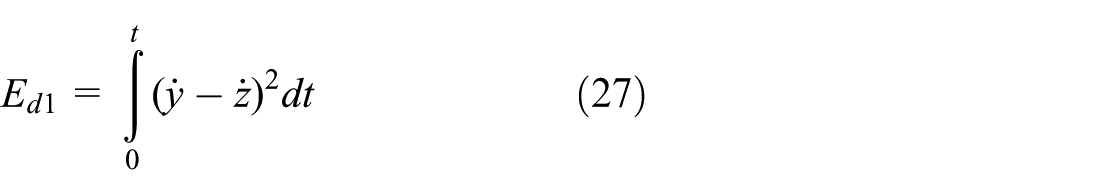
Energy dissipated in the adjustable damper is given as follows

Figure 14 illustrates simulation results for energy dissipated in the damper for the disclosed setting. Energy dissipation increases as the number of active orifice holes increases.

Energy dissipated by the adjustable damper.
The conceived system comprises of linear viscous damper, connected in parallel to the helical spring. This will result in stiffness being dynamic rather than static. Therefore, the dynamic stiffness needs to be investigated. Dynamic stiffness is investigated as either synchronous or non-synchronous. 28 Synchronous stiffness is related to the machine excitations and the input excitation being of identical frequency.

where F is the excitation force and R is the response.
Theoretical simulations for the dynamic stiffness have been performed with 12 numbers of holes in the piston orifice. Figure 15 shows the dynamic stiffness for the prototype with different configurations of the damper. It can be observed that 12 holes open setting has the value increasing along the frequency. For two holes open setting, maximum dynamic stiffness is observed at about 8 Hz. Moreover, the value increases at higher frequency. Numerical simulations have also been performed to reveal dynamic stiffness of a passive system with fixed elastic configuration. It shows peak value at about 5 Hz and reduces thereafter. Moreover, it shows increased stiffness at higher frequency. As revealed by Figure 15, peak dynamic stiffness does not coincide with natural frequency. Moreover, nature of the curves is identical for the proposed system than that of the passive solution.

Simulation results for dynamic stiffness.
Stiffness of an automobile shock absorber is calculated as follows

where
Damping coefficient is also given as follows

where
It can be observed from equation (14) that reduction in the vehicle mass will increase the heave natural frequency. Therefore, lower suspended mass will give harsher ride. The stiffness should be reduced to ensure consistent damping performance. Moreover, equation (15) indicates that lower suspended mass requires reduced damping coefficient for consistent comfort level.
The conceived system performs energy dissipation in addition to that providing elastic property. Damping coefficient has been calculated in accordance with the relative velocity between sprung and un-sprung mass and is calculated as follows

Damping coefficient achieved by the prototype is 625 N s/m (i.e. peak damping force of 348 N at relative velocity of 0.556 m/s, for 8 Hz excitation frequency). However, peak damping coefficient does not remain same and varies as shown in Figure 16. The damping coefficient is maximum near the resonance frequency of the system (i.e. at 4.5 Hz for setting with eight holes open in the prototype). The increase in damping coefficient may be attributed to resonant movement of the suspended mass. Energy dissipation in the adjustable damper has been taken into consideration while designing the real size shock absorber.

Variation of the damping coefficient.
Numerical simulation has been performed to compute time lag between the sprung and un-sprung mass for different settings of the adjustable damper. Simulation results for 4 and 12 holes open condition are given in Table 3. It can be observed from the simulation results that at frequencies lower than 4 Hz, phase lag is higher for softer damper settings. However, at higher frequencies, phase lag is reduced for softer damper setting.
Phase lag between sprung and un-sprung mass.

Increased time delay for hard damper setting may be attributed to lower energy dissipation at lower frequencies. However, the damper offers relative displacement at higher frequencies, resulting in greater time lag.
Design of real size variable stiffness system
After validating the prototype variable stiffness system, design of real size shock absorber with variable stiffness and damping has been discussed in this section. The design of real size version has been performed for the vehicle and suspension mass as follows:
Sprung mass (m1): 275–400 kg;
Un-sprung mass (m2): 25 kg;
Tire mass (m3): 10 kg;
Spring stiffness (k1): 12,500 N/m;
Spring stiffness (ks): 12,500 N/m.
Numerical model and modified quarter car model for simulation of the real size shock absorber are shown in Figure 17(a) and (b).

(a) Numerical model for the real size design and (b) modified quarter car model.
Governing differential equations for the model shown in Figure 17 are given as follows


The real size shock absorber has been designed to deliver consistent performance for the sprung mass between 200 and 300 kg. Values of the adjustable dampers ‘C1’ and ‘bs’ have been varied to achieve the desired equivalent stiffness and damping, as discussed in the following.
Natural frequency of the equivalent system shown in Figure 17(b) can be calculated as follows

Equivalent stiffness of the system is determined by comparing potential energy of the actual and equivalent system, that is

Simplifying the above equation, equivalent stiffness of the system is written as follows
Furthermore, the ratio of

where w is the angular velocity of excitation
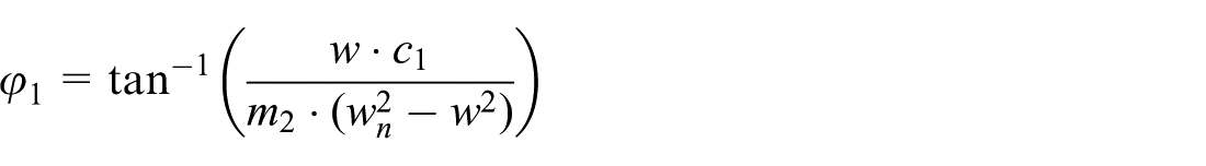

where
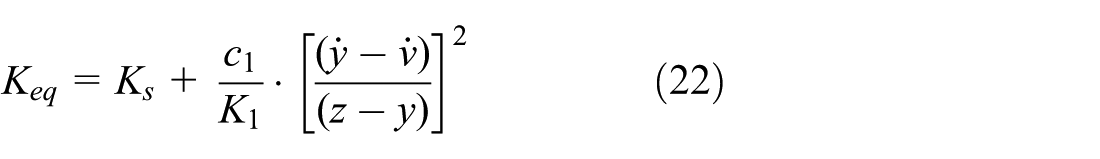
Dynamic stiffness of the real size shock absorber is calculated with equations (21) and (22). Similarly, equivalent damping is calculated by comparing work done in dissipating the energy by actual and equivalent systems
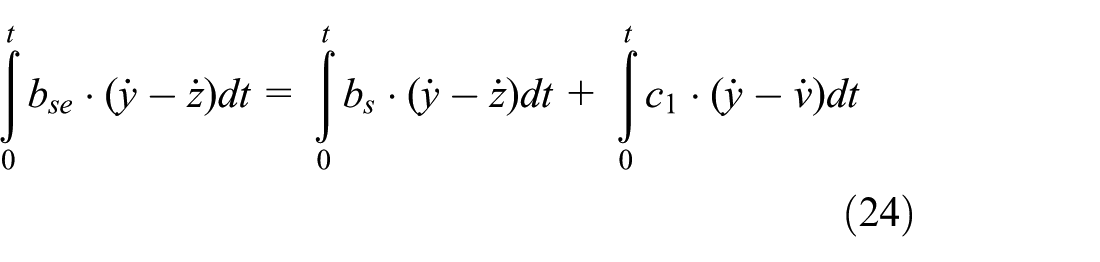
where
Simplifying

Dynamic simulation of the system is necessary to validate equivalent stiffness of the system. This is because a damper is incorporated in the system in series with a spring and energy dissipation and vibration isolation characteristics of the shock absorber are dependent on the adjustable damper connected in series with the spring. It can be observed from equation (22) that the equivalent stiffness of the system will be higher than that of ‘ks’. Furthermore, its value will depend on damping coefficient ‘C1’ and ‘k1’. On the other hand, equation (24) indicates that equivalent damping coefficient of the system will be higher than ‘bs’.
Simulations are performed on the numerical model of real size design to reveal force–displacement characteristics. Furthermore, the curve is compared to that of the passive shock absorber with fixed energy dissipation characteristics. Figures 18–20 compare force–displacement curve for the proposed variable stiffness system and conventional passive solution. The proposed system modulates the suspension damping coefficient according to the sprung mass supported by the vehicle. It is evident that reduction in the damping coefficient lowers peak damping force and improves sprung mass acceleration. The shock absorber offers lower value of damping coefficient ‘C1’, which reduces peak damping force. This results in better acceleration transmissibility at the sprung mass. On the other hand, passive damper with fixed damping configuration gives higher damping force as observed from Figure 17(b), which results in higher sprung mass acceleration.
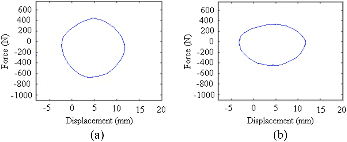
Force–displacement curve at 4 Hz frequency: (a) bs = 1400 N s/m, C1 = 60, Ks = 17.3 kN m and m1 = 275 kg and(b) bs = 2000 N s/m, Ks = 17.3 kN m and m1 = 275 kg – passive damper.

Force–displacement curve at 6 Hz frequency: (a) bs = 1400 N s/m, C1 = 60, Ks = 17.3 kN m and m1 = 275 kg and(b) bs = 2000 N s/m, Ks = 17.3 kN m and m1 = 275 kg – passive damper.

Force–displacement curve at 8 Hz frequency: (a) bs = 1400 N s/m, C1 = 60, Ks = 17.3 kN m and m1 = 275 kg and(b) bs = 2000 N s/m, Ks = 17.3 kN m and m1 = 275 kg – passive damper.
The real size system is designed for obtaining consistent damping performance for the following load steps:
Stiffness setting in the real size design
Referring to Figure 17(b), the real size shock absorber will change its stiffness in five steps depending on the sprung mass. The adjustable damper with damping coefficient of ‘C1’ will block the fluid flow for maximum value of the sprung mass. Furthermore, as the sprung mass is reduced, the adjustable damper will provide proportional oil flow.
Natural angular velocity for the 2-degree-of-freedom quarter car model illustrated in Figure 17(b) is given by equation (20). Heave natural frequency of a passenger car is about 1.2. 1 Higher stiffness deteriorates passenger comfort. On the other hand, lower stiffness affects vehicle handling. Referring to equation (22), desired stiffness settings for different values of the sprung mass are given in Table 4.
Stiffness settings for the real size model.

Table 4 shows that for the given change in the sprung mass, the suspension stiffness needs to be varied by 31% (i.e. (25–17.3)/25 = 30.8%) to ensure vibration isolation in the suspension.
Real size shock absorber will have adjustable damper with damping coefficient ‘C1’. The damping intensity of this adjustable damper will be varied. Number of iterations has been made with the Simulink model of real size shock absorber to derive damping coefficient ‘C1’ for the various values of sprung mass to obtain the desired suspension stiffness and are given in Table 5.
Damping coefficient for the adjustable damper.

Damper setting in the real size design
Design damping coefficient for the given sprung mass has been calculated based on the procedure available in the literature. 1

The real size shock absorber is designed to deliver variable damping coefficient as per the sprung mass variation. The damping coefficient of the damper ‘bs’, shown in Figure 17(b), will be varied with respect to the frequency in the steps as given in Figure 21.

Variation of the damping coefficient ‘bs’.
The stiffness variation has been achieved to the extent to suit the present application. The presented design will perform better than its passive counterpart, even if the sprung mass varies by 100 kg. However, with further variations in the values of ‘C1’ and ‘k1’, higher variation in the equivalent stiffness can be achieved.
Simulations are performed on the Simulink model of the real size design to reveal variation of the equivalent stiffness along the frequency range. Figure 22 shows the simulation results for different values of ‘C1’.
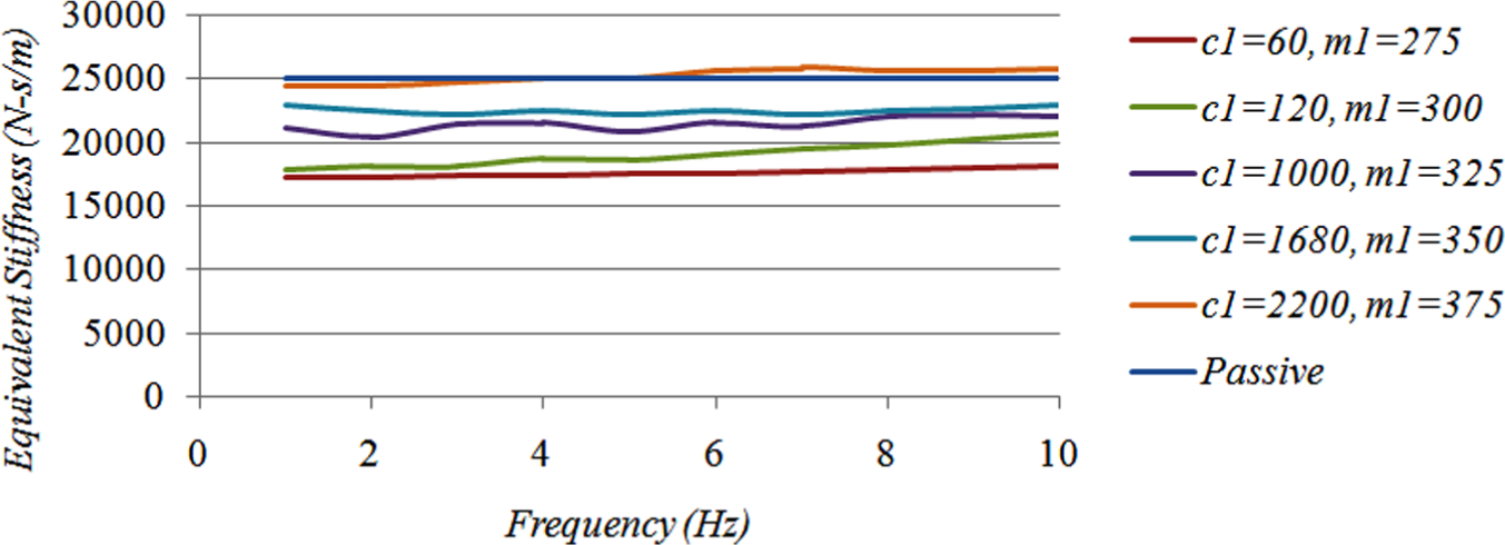
Equivalent stiffness of the real size shock absorber.
Figure 22 shows that equivalent stiffness of the system can be varied by up to 32% (i.e. (25–17.6)/25) in the proposed arrangement. Although the equivalent stiffness shows smoother variation, there is marginal increment (∼5%) at higher frequency. Simulation results indicate that with rising value of damping coefficient, ‘C1’, the equivalent system stiffness increases.
For lower value of the damping coefficient ‘C1’, the equivalent stiffness is 17.5 kN/m (i.e. close to
Energy dissipated by the real size shock absorber is given as follows
Similarly, the energy dissipated with the adjustable damper connected in series with the spring is given as follows

Simulations are performed with the real size model to calculate percentage of energy dissipated by damper 2, in comparison to the overall damping. The simulation results are summarised in Table 5, which indicates that higher value of C1 does not significantly contribute to the system damping. This is because higher values of C1 reduce relative velocity and displacement between y and v. On the other hand, for lower values of C1, its contribution in overall damping is not significant. Therefore, it can be concluded that the additional damping due to C1 significantly affects the system equivalent stiffness. However it does not influence the damping properties significantly.

Valve model to achieve the desired damping strategy
Energy dissipation in fluid dampers is achieved by throttling viscous fluid through restricted orifices. Moreover, variable flow area in the spring loaded valve ensures variable damping intensity. Valve models are used to specify possible combinations of piston orifices. 1 Damping strategy shown in Figure 21 can be achieved with combinations of fixed and spring loaded variable area valves in the piston of the fluid damper.
Valve model shown in Figure 23 is a two-stage model with fixed and variable flow paths. The intermediate chamber between the compression and rebound chamber is connected with variable flow paths:
P 1 is the pressure in compression chamber;
P 2 is the intermediate chamber pressure;
P 3 is the rebound chamber pressure;

Two-stage valve model.
Referring the valve model shown in Figure 23, flow through fixed flow path is given as follows
Flow through two-stage variable flow path will be identical

Also total flow

Total flow is given as follows

Simplifying equations (29)–(32)

Since oil low rate depends on piston velocity

where area in compression and rebound stroke is given as follows


Equations (30) and (31) are rewritten to obtain damping coefficient as follows

‘DH’ is the hydraulic diameter which is given as follows
where A is the orifice passage area.
Referring to the available literature, 29 pressure drop in the compression and rebound chamber is given as for the single-stage valve model, as shown in Figure 24


Single-stage valve model.
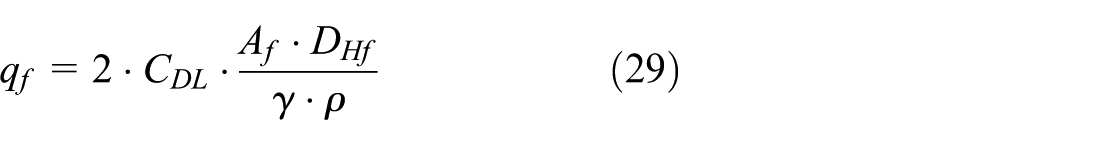
Further damping coefficient in compression and rebound chamber can be obtained from equation (36) as follows

Equations (36)–(38) can be used to compute damper configuration for desired damping coefficient. It has been demonstrated that change in damping intensity will lead to consistent vibration isolation performance. To achieve the desired damping strategy, number of fixed openings ‘ηf’ has been varied to get desired damping intensity.
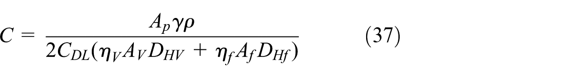
Two-stage valve model that has been discussed earlier has been used to derive the damper configuration for damper 2. The desired damping coefficient ‘bs’ can be obtained by changing number of fixed holes in the piston orifice. Detailed valve model is given in Tables 6 and 7.
Details of fluid damper 1.

Number of fixed holes in damper 1.

Single-stage valve model as discussed earlier has been used to derive the damper configuration to achieve the damping coefficient illustrated in Table 5. Number of fixed holes ‘nf’ will be varied to change the damping intensity.
Details of the damper are given as follows:
Af = 1.2 mm2.
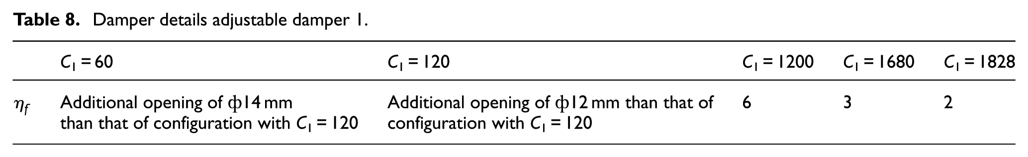
Further numbers of fixed opening (
Damper details adjustable damper 1.
Simulation results for the real size shock absorber with variable stiffness and damping
Simulation of real size shock absorber has been performed in MATLAB Simulink and Simscape for the quarter car model shown in Figure 17(a). Details for spring stiffness and damping coefficient of dampers 1 and 2 are discussed earlier. MATLAB model for the shock absorber is shown in Figure 25.

MATLAB model for the real size shock absorber.
In the numerical analysis, quarter car model is based on equations (17) and (18). Furthermore, this model is used to compute the shock absorber relative displacement and velocity which are used by the Simscape model to calculate pressure drop across the fluid damper and damping force. The damping force is again used by quarter car model to find the shock absorber performance parameters.
Numerical simulation results for sprung mass acceleration of the variable stiffness and damping shock absorber are given in Figure 26(a). Furthermore, the sprung mass acceleration for conventional passive shock absorber is plotted in Figure 26(b). It can be observed that variable stiffness and damping solution will provide improvement in acceleration transmissibility by up to 15% (conventional shock absorber acceleration: 5.0 m/s2, proposed solution acceleration: 4.3 m/s2, at 6 Hz for sprung mass of 275 kg).

(a) Sprung mass acceleration of the real size shock absorber and (b) sprung mass acceleration of conventional shock absorber.
It can be observed from Figure 26(a) and (b) that the acceleration increases up to certain frequency. Thereafter, the rate of change of acceleration reduces and again increases. Change of acceleration within certain frequency range is attributed to the presence of anti-resonance frequency. It is reported that acceleration response reduces at the anti-resonance frequencies. 12
Root mean square (RMS) tire deflection is the criteria used to evaluate handling or tire discomfort of an automobile shock absorber.29,30 Best handling is achieved for zero RMS tire deflection, whereas higher deflection deteriorates vehicle cornering and handling capability. Figure 27(a) and (b) compares RMS tire deflection for the proposed solution with that of conventional fluid damper. It can be observed that the proposed solution gives up to 10% improvement in tire discomfort (conventional shock absorber: 7.1 mm, proposed solution: 6.5 mm, at 6 Hz for sprung mass of 275 kg). Peak transmissibility of the proposed shock absorber will be lower than that of conventional fluid shock absorber, as observed from Figure 28(a) and (b).

RMS tire deflection of (a) the real size shock absorber and (b) conventional shock absorber.

Peak transmissibility of (a) the real size shock absorber and (b) conventional shock absorber.
Fitment of the real size shock absorber
The real size shock absorber will be fitted in the vehicle along with a load cell, LPC2138 microcontroller, stepper motor and a mechanism for opening and closing orifice fixed hole. Block diagram for implementation of the real size shock absorber is shown in Figure 29. The microcontroller and stepper motor will operate with 24 V DC supply, which will be provided by a switched mode power supply (SMPS). The microcontroller will convert the analogue voltage signal into digital, which will be further filtered to obtain mass of the vehicle when it is at rest. Therefore, the controller will not process dynamic signals from the load cell, during the vehicle movement on road. The digital signal will decide degree rotation of the stepper motor shaft. Accordingly, stepper motor will be provided with the number of pulses.

Block diagram for the real size shock absorber.
Arrangement of the stepper motor, springs and adjustable damper is shown in Figure 30. For each of the pulse from the controller, the stepper motor will rotate by 1.8°. A gear with 50 numbers of teeth will be used to magnify this rotary motion to 7.2° for each of the pulse. Furthermore, this rotary motion will be operating the mechanism used for changing number of fixed holes in the piston orifice.

Arrangement of the real size shock absorber.
The literature review indicates that most of the semi-active suspension systems vary the properties in response to the vertical stimulus velocity. However, this work deals with variation of the suspended mass. Few of the systems discussed in the literature are compared with this work for comfort and handling evaluation. Azadi et al.20,21 developed a variable stiffness mount with pre-stressed cable-based mechanism. The stiffness has been varied from 160 to 510 N/mm. In the similar work, Zhou et al. 7 implemented adjustable MR damper in parallel with a spring to achieve stiffness variation up to four times. However, with implementation of velocity sensor and MR damper, cost becomes higher. Adjustable fluid dampers have been used in semi active dampers to achieve improvement in acceleration transmissibility.31–32,4. However, the damping properties are varied in response to the stimulus velocity, rather than suspended mass. Xu and Ahmadian 3 investigated variable stiffness and damping model for handling evaluation of the vehicle. Up to 8% improvement in longitudinal and vertical displacement has been reported.
Conclusion
Design and numerical simulation of a variable stiffness system have been presented in the article. Helical springs and adjustable fluid damper have been used in the prototype to vary the stiffness from 43.5 to 53.8 kN/mm. Numerical simulation has been performed in MATLAB Simscape and experimentations have been performed to validate the theoretical model.
Theoretical model has been used in design of a real size shock absorber. Configuration of the adjustable damper has been determined to ensure consistent damping performance, irrespective of the change in sprung mass. Detailed damper configuration has been derived with single- and two-stage valve model. Quarter car simulation has been used to quantify comfort and handling evaluation. Simulation results indicate that the proposed system will give 15% improvement in acceleration transmissibility and tire discomfort, in comparison to conventional fluid passive shock absorber.
Footnotes
Academic Editor: Ling Zheng
Declaration of conflicting interests
The author(s) declared no potential conflicts of interest with respect to the research, authorship and/or publication of this article.
Funding
The author(s) received no financial support for the research, authorship and/or publication of this article.