
Abstract
Nickel-based superalloys such as Waspaloy are used for engine components and in the nuclear industry, where considerable strength and corrosion resistance at high operating temperatures are called for. These characteristics of such alloys cause increases in cutting temperature and resultant tool damage, even at low cutting speeds and low feed rates. Thus, they are classified as difficult-to-cut materials. This article presents a cooling method to be used in metal cutting based on a tool holder with a closed internal cooling system with cooling fluid circulating inside. Hence, a green cooling method that does not harm the environment and is efficient in removing heat from the cutting zone was developed. A series of cutting experiments were conducted to investigate the practicality and effectiveness of the internally cooled tool model. The developed system achieved up to 13% better surface quality than with dry machining, and tool life was extended by 12%. The results clearly showed that with the reduced cutting temperature of the internal cooling, it was possible to control the temperature and thus prevent reaching the critical cutting temperature during the turning process, which is vitally important in extending tool life during the processing of Waspaloy.
Introduction
The machining of superalloys has become an important manufacturing process, particularly in the automotive, aerospace, and gas turbine industries. Aerospace materials such as titanium and nickel-based alloys exhibit poor machinability owing to their excellent physical properties which include low thermal conductivity and high hardness at elevated temperatures. 1 Nickel-based superalloys such as Inconel 718, Waspaloy, and Niobium have been widely employed in missile technology and other defense applications due to their strength at high temperatures. 2 These characteristics cause increases in cutting temperature and resultant tool damage, even at low cutting speeds and low feed rates. Thus, they are classified as difficult-to-cut materials. The machinability of superalloy materials is much more difficult compared to that of steels and stainless steels. 3 The challenge and difficulty in cutting Waspaloy is due to its profound characteristics such as high shear strength, tendency to weld and form built up edge, low thermal conductivity, and high chemical affinity. 4 Due to these characteristics, Waspaloy is not easy to cut and thus has been regarded as a difficult-to-cut material.
The important requirements for machining are increasing the material removal rate, increasing the surface quality, and lowering the energy consumption. These objectives are achieved through reduction in tool wear using a suitable tool–cooling system during operation. In the machining process, a significant amount of energy is converted into heat through plastic deformation and chip formation by friction between the tool and the chip and between the workpiece and the tool face. 5 The wear and thermal damage of the cutting tool can increase at higher temperatures, thus shortening tool life and, consequently, resulting in poor surface quality.2,6 Compared to other materials, the most significant characteristic of nickel-based superalloys is that they are usually much stronger at metal-cutting temperatures.
Cutting fluids have been used for many years to reduce the temperature during processing, with the effects of reducing the tool temperature and improving tool life and the quality of the product. However, the use of cutting fluids can cause environmental pollution, health hazards, and high production costs.6–8 Cutting fluids are useful to minimize chip contact length with the cutting tool, to reduce the cutting temperature and the thermal deformation of the workpiece, to flush away the cutting chips, to decrease the cutting force by lowering the cutting temperature, and to improve the tool life and the surface condition of the workpiece.9,10
According to Dhar et al., 11 there are some disadvantages of using cutting fluids, including added costs from additional storage needs, pumping, filtering and recycling, occurrence of cutting fluid gases, and potential operator health problems caused by smoke and bacteria. In addition, cutting fluids pose a risk of skin cancer to operators after long exposure.
Sreejith and Ngoi 12 proposed a dry processing method involving indirect contact with the cutting zone as an alternative cooling method. They introduced an internal cooling system that flowed through the channels below the cutting zone for cooling without direct contact with the insert. Shu et al. 13 presented a novel approach for measuring the cutting temperature during the process and controlling it to some extent using an internally cooled smart cutting tool with a closed internal cooling circuitry. In turn, Vicentin et al. 14 used a cooling system for a cutting tool based on a tool holder with coolant circulates. The developed internally cooled tool (ICTool) system achieved a superior surface roughness compared to dry machining. An ICTool for dry cutting was designed and analyzed by Sun et al. 6 The cutting tool was characterized by a simple, replaceable internal cooling structure, close to the cutting edge. Simulations were employed to examine the theoretical cooling efficiency, and the Taguchi method was carried out to optimize the cooling by combining the structures. Zhao et al. 15 carried out a simulation using an internal cooling device with which it was possible to reduce the cutting temperature and surface abrasion flank wear. Ghani 16 investigated an environmentally sensitive internal micro-cooling method designed to reduce the cutting temperature and prevent contamination of the part.
This article presents a new approach using a holder with an ICTool method. A prototype tool holder that facilitates cooling was specially designed and manufactured. Experimental trials were conducted on Waspaloy AMS5708 superalloy samples. A number of tests were conducted to investigate the practicality and efficiency of the ICTool concept, and the results were compared with those of dry cutting.
Experimental procedures
Design and production of the tool holder
The idea of ICTool began with the identification of the demand and requirements from the end-users, particularly the needs for high machining economics and efficiency in green manufacturing. The internal structure of the tool holder was designed to be as close as possible to the cutting edge and achieve maximum heat transfer rate. Holes of 2 mm opening into the holder for entry and exit of the fluid were used for coolant circulation throughout the tool, and the fluid was in direct contact with the cutting insert. The cooling fluid used was purified water at a temperature of 18°C. Cooled water was pumped continually from a pure water container to the inlet and back to the container from the outlet forming a closed-loop internal cooling system. The technical specifications of the pump used in the experiments were as follows: an ARWANA IGP-90 device operating with an inlet fluid pressure of 0.6 × 10⁵−3.8 × 10⁵ Pa and a flow rate of 0.5–2.0 m3/h. Owing to its high specific heat capacity, water was provided as the coolant. In order to prevent the metallic parts from oxidizing in the water, corrosion inhibitors were added. A detailed schematic diagram of experimental setup is shown in Figure 1, and the fluid applicator is shown in Figure 2. A conceptual illustration of the ICTool structure is shown in Figure 3, and the tool holder with slots is shown in Figure 4.

Detailed schematic diagram of experimental setup.

Fluid applicator.

Conceptual model of the ICTool.
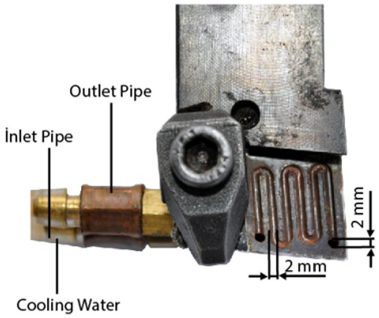
Slots and holes of the tool holder.
Experimental setup
The effects on Waspaloy’s machinability and the performance of the ICTool process were examined in this study. Experimental conditions are shown in Table 1. Round Waspaloy AMS5708 bars of 38 mm in diameter and 300 mm in length were used in the experiments. A chemical vapor deposition (CVD)-coated CNMG 190604-IC907 carbide insert was used during the turning process. The cutting insert was indexed, and a brand new edge was introduced after each trial. The schematic view of the tool holder and cutting insert are shown in Figure 5.
Experimental conditions.

CVD: chemical vapor deposition.

Schematic view of the tool holder and cutting insert.
The chip–tool interface temperature was measured using an Optris CF4 infrared (IR) pyrometer. The emissivity value of 0.60 was determined on the CVD-coated tungsten carbide cutting surface for the temperature range of 385°C–1600°C. The measurement point was 1.5 mm in size, corresponding to the distance to the 0.6-mm measurement surface. 17 The accuracy of the system was ±0.3% for a reading of +2°C. For this study, the tool temperature was measured using a K-type thermocouple. The accuracy of the tool temperature measurements using the K-type thermocouple data acquisition system was ±2.5°C or ±1%. The thermocouple and IR pyrometer setup is shown in Figure 6.
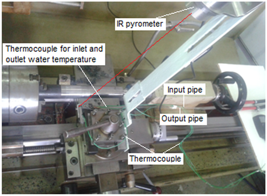
Thermocouple and IR pyrometer connection in the tool holder.
Workpiece material
Nickel-based superalloys currently have hard, abrasive carbides in their microstructure that allow the development of abrasive flank wear. Their high dynamic shearing strength during the cutting process results in localized shearing stresses, and their properties of high strength and hardness at high temperatures are responsible for the deformation of cutting tools during the cutting process.18,19 The volume % chemical composition of Waspaloy is shown in Table 2.
Chemical composition of Waspaloy (vol.%). 20

Experimental study
A series of cutting experiments were conducted to investigate the practicality and effectiveness of the ICTool holder. In total, 18 (3 × 3 × 2) combinations of turning trials were carried out to complete the series of cutting experiments. For this study, the tool temperature was measured using a K-type thermocouple, and the chip–tool interface temperature was measured using an Optris CF4 IR pyrometer. Five measurements were recorded by the pyrometer every second. Each test was repeated three times under the same cutting conditions, and the average of the measured values was recorded. A series of trials were conducted at different cutting speeds, and the surface roughness values were measured using a portable TIME TR200 device. After each turning test, surface roughness was measured at intervals of 120° on the outer diameter, and the average of the values was recorded. The average width of the flank wear (Vb) was adopted as indication of the tool wear. Flank wear was measured using a Nikon104 microscope with a magnification of ×10. A workshop microscope with the minimum graduation of 0.01 mm was used in the measurement.
Results and discussion
Effectiveness of cutting speed and temperature reduction
During the cutting process, an increase in the temperature was observed depending on the processing time. This was due to the tool wear and the increased friction at the cutting zone. Moreover, a large amount of the heat was removed from the workpiece by the chip. As the cutting speed increased, more heat was removed. However, the increase in cutting speed increased the temperature abruptly. 19 Therefore, the cutting speed is an important influential factor on tool wears and tool life when cutting nickel-based alloys. In the experiments, the influence of cutting speed and inlet velocity on the tool–chip interface and tool temperatures of the Waspaloy samples was observed under dry conditions and with the ICTool. The relationship was investigated between the cutting parameters and the cutting temperature recorded by the remote temperature measurement method under dry conditions and with the ICTool. It was observed that the highest cutting speed generated a higher cutting temperature at the tool–chip interface, which meant that the cutting speed was the most effective parameter. Comparisons of temperatures under the dry and internally cooled cutting conditions are shown in Table 3.
Comparisons of tool–chip interface and tool temperatures under dry and internally cooled conditions (f = 0.10 mm/rotational speed and a = 0.5 mm).

ICTool: internally cooled tool.
Under dry conditions, the temperature measurement via IR pyrometer indicated that for a speed of 45 m/min, the maximum temperature was 456°C. As the cutting speed increased from 45 to 95 m/min, the maximum temperature reached 641°C, with an increase rate of 28%. A higher cutting speed meant more plastic deformation in the workpiece; therefore, more mechanical energy was converted into heat energy, and the temperature increased significantly. Thus, the substantial increase in the temperature was the result of the material characteristics of the Waspaloy. The maximum tool–chip interface temperature of 641°C was reduced to 587°C by internal cooling, a decrease rate of 9%. This clearly indicated that the internal cooling was sufficient to reduce the cutting temperature and avoid the critical cutting temperature, allowing the cutting tool to work by controlling its temperature.
Using internal cooling, it was possible to determine the critical temperature that would bring about rapid tool failure. The ICTool was effective in reducing tool–chip interface temperatures at all cutting speeds. There is a linear relationship between cutting speed and temperature, even with a low coolant flow rate. Figure 7 shows the tool–chip interface temperature differences for the dry conditions and for the ICTool holder at various cutting speeds. With the use of an internal coolant, a higher temperature difference was obtained at high cutting speeds. Tool temperatures under dry and ICTool conditions are shown in Figure 8.
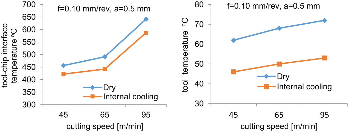
Tool–chip interface temperatures at different cutting speeds.

Tool temperatures under dry and internal cooling conditions.
Temperature correlations with flank wear andtool life
The tool wear aspect of tool life is significantly influenced by the temperature generated at the cutting zone, especially for low thermal conductivity alloys such as Waspaloy. When cutting Waspaloy, the most recognizable type of tool wear is the flank wear formed by the cutting speed due to the high thermal combination. The experimental trials indicated that using an ICTool, the temperature was controlled as well as the wear mechanism, and thus, tool life was extended. The reference flank wear value according to the International Standard Organization (ISO 3685) of Vb = 0.3 mm was chosen as the wear criterion. A cutting tool was rejected, and further machining was stopped based on a combination of the rejection criteria in relation to ISO 3685 for tool life testing. The wear mechanism is affected by the cutting temperature; low cutting temperatures can minimize the development of tool wear. According to the experimental results, it was possible to extend the tool life up to 12% by the use of the internal cooling method. Flank wears and tool life for the ICTool and dry conditions are shown in Figure 9(a).
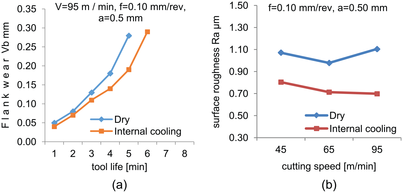
Comparisons for various cutting speeds: (a) flank wear and (b) surface roughness.
Effectiveness of temperature reduction for surface roughness
There is a clear-cut relationship between cutting speed and surface roughness. The softening of the material due to increased temperature results in a smoother finish and, thus, lower surface roughness. The cutting speed and internal cooling were recognized as having a positive effect on surface quality. Using the internal cooling method, as the cutting speed increased, the quality of the surface improved. The lowest roughness value was shown to be Ra = 0.699 µm at a cutting speed of 95 m/min, an inlet velocity rate of 1.6 m/s, and a depth of cut of 0.5 mm. The developed system provided up to 13% better surface quality than with dry machining. The tool–chip interface temperature and the surface quality showed significant improvements after applying internal cooling. Figure 9(b) shows surface roughness comparisons under the dry and internally cooled conditions at various cutting speeds. The maximum levels of both coolant flow rate and cutting speed resulted in the highest surface quality.
Conclusion
The work material in this experimental study was Waspaloy, which is costly and exhibits poor machinability. The major findings of this work can be summarized as follows:
The cutting speed is an important influential factor on tool wears and tool life when cutting nickel-based alloys. Higher cutting speed means more plastic deformation in the workpiece owing to the material properties of Waspaloy; therefore, more mechanical energy is converted into heat energy, and the temperature increases significantly. The experimental trials indicated that using the ICTool, the temperature was controlled, as was the wear mechanism, and thus, tool life was extended.
As the cutting speed was increased from 45 to 95 m/min, the maximum temperature reached was 641°C, an increase in the temperature rate of about 28%. The maximum tool–chip interface temperature of 641°C was reduced to 587°C by internal cooling, a decrease rate of 9%. This clearly indicated that internal cooling can sufficiently reduce the cutting temperature and enable the cutting tool to work while avoiding the critical cutting temperature by controlling it during the process.
The experimental trials indicated that using the ICTool, both the temperature and the wear mechanism were controlled, and thus, tool life was extended. According to the test results, using the ICTool method, it was possible to extend tool life by 12% compared with dry machining, therefore avoiding environmental hazards and health risks.
The cutting speed and internal cooling were recognized as having a positive effect on surface quality. As the cutting speed increased, the surface quality improved with the ICTool method. The developed system achieved up to 13% better surface quality than with dry machining.
Footnotes
Academic Editor: M Ravichandran
Declaration of conflicting interests
The author(s) declared no potential conflicts of interest with respect to the research, authorship, and/or publication of this article.
Funding
The author(s) received no financial support for the research, authorship, and/or publication of this article.