
Abstract
This article focuses on the design of a control system for intelligent prostheses. Learning vector quantization neural network–based model reference adaptive control method is employed to implement real-time trajectory tracking and damp torque control of intelligent lower-limb prosthesis. The method is then analyzed and proposed. A model reference control system is first built with two learning vector quantization neural networks. One neural network is used for output prediction, and the other is used for input control. The angle information of the prosthetic knee joint is utilized to train these two neural networks with the given learning algorithm. The testing results of different movement patterns verify the effectiveness of the proposed method and its suitability for intelligent lower-limb prostheses.
Keywords
Introduction
Intelligent coordination control of lower-limb prostheses has recently elicited considerable attention in the field of prosthetics. Intelligent lower-limb prostheses allow lower extremity amputees to regain some of their abilities and greatly improve their daily life.1–3 Intelligent lower-limb prosthesis generally refers to a prosthetic limb fitted with an intelligent knee joint; the knee joint automatically adjusts its damping torque with the changes in walking pace and joint angle, thereby making its gait close to the gait of the healthy side in terms of tracking and symmetry.4,5 The intelligent knee joint is typically a damping system that is highly nonlinear, time variant, and strongly coupled; it is influenced by uncertain factors, such as friction and load. 6
Intelligent prostheses have been produced for upper and lower limbs. The control strategies for upper-limb prostheses were developed earlier than those for lower-limb prostheses. In a previous study, 7 an electromyography (EMG)-based impedance control method for an upper-limb power-assist exoskeleton robot was proposed to control the robot in accordance with the user’s motion intention. A neurofuzzy matrix modifier was applied to allow the controller to adapt to any user. This method is simple, easy to design, human-like, and accommodates any user. Another previous study 8 investigated two surface EMG-based control strategies developed for a power-assist exoskeleton arm. In contrast to most existing position control methods, force control was developed to compel an exoskeleton robot to behave like a human and provide improved assistance.
The control methods for intelligent lower-limb prostheses are developed based on those for upper-limb prostheses. Various control algorithms have been proposed to implement the real-time trajectory tracking and real-time damping torque control. 9 The tracking target is generally a flexion angle of the knee joint and time curve, and the controlled object is generally the knee-joint damper. 10 Under this circumstance, two conditions need to be satisfied in the design of an intelligent prosthesis controller. First, to follow the prosthetic movement in real time, the controller should have fast learning and tracking abilities. Second, this controller should have a high movement pattern recognition rate and a good control function. 11
The control methods for intelligent lower-limb prostheses are categorized into two, namely, expert control and neural network (NN) control methods. Many scholars have developed respective control algorithms derivative from these two methods. Zlatnik et al. 12 adopted an expert control method called sequence finite-state machine and achieved the multi-locomotion mode control of lower-limb prostheses. Meng et al. 13 utilized a method called finite-state machine and succeeded in making the prosthetic side follow the healthy side in real time. Kostov et al. 14 succeeded in helping a paralyzed patient control the joints outside his thigh with the NN method. Kalanovic et al. 15 successfully integrated an error back-propagation NN controller and a proportional–integral–derivative (PID) controller into a lower-limb prosthesis control system. Taherifar et al. 16 designed a novel control system of exoskeletons for load carrying and power augmentation; the control method in this system is based on a kinematic model and is thus easy to implement.
These studies implemented gait tracking and damping control for prosthetic limbs at various degrees of precision. Many other control methods have been employed to pursue an equally good or even better effect. This study adopted the model reference adaptive control system (MRACS) because of its good stability and convergence and its simple design. 17 MRACS can establish a closed loop controller with the help of a reference model; MRACS can regulate the parameters of this controller to achieve the desired response. 18 Moreover, the learning vector quantization (LVQ) NN exhibits good pattern recognition performance and allows for the selection of many selection algorithms for increased classification effectiveness. 19 Thus, the use of LVQ NN in MRACS was considered in this study.
To implement real-time gait tracking and damping torque control of intelligent lower-limb prosthesis, the LVQ NN-based model reference adaptive control (MRAC) method is adopted in this study. First, MRACS is built with two LVQ NNs. One NN is used for output prediction, and the other is used for input control. The angle information of knee joints serves as the training sample. The two NNs are trained with the LVQ NN learning algorithm. An intelligent lower-limb prosthesis system is designed to verify the effectiveness of the proposed adaptive control method. Experiments with different movement patterns are conducted with this method. The testing results prove that the proposed method is effective and suitable for intelligent lower-limb prostheses.
This article is organized as follows. Section “Introduction” presents the basic principle of LVQ NN. The corresponding learning algorithm is also presented. The intelligent lower-limb prosthesis control system is introduced in section “LVQ NN.” The design of NN-based MRACS, including its structured frame and object recognition model, is discussed in section “Intelligent lower-limb prosthesis control system.” In section “LVQ NN-based MRAC method,” experiments on the prosthesis are conducted with different movement patterns to verify the effectiveness of the proposed model reference system. The conclusions are presented in the final section.
LVQ NN
Basic principle of LVQ NN
LVQ NN is an extension of self-organizing competitive NN. 20 It has two layers. The first layer, which is called the competitive layer, is utilized to classify input vectors. The second layer, which is called the linear layer, is utilized to transform the classification information from the competitive layer into the expectation classes defined by users.21,22 The class from the competitive layer is generally defined as the subclass, whereas the class from the linear layer is defined as the expectation class. Figure 1 shows the structural model of LVQ NN.

Structural model of LVQ NN.
In Figure 1, R, S1, and S2 represent the number of input vector elements, number of competitive layer neurons, and number of linear layer neurons, respectively. The input vector, output vector of the competitive layer, and output vector of the linear layer are denoted by p, a1, and a2, respectively.
The relationship between subclasses and expectation classes can be summarized in the following statements. In the competitive layer, if the ith element of input vector p wins the competition, the element in row i of vector
LVQ NN learning algorithm
If vector T is the target vector of a training sample set and K* represents the class obtained from training, then the LVQ learning rules are as follows:
If the classification is correct, that is,

If the classification is incorrect, that is,

where
However, if two vectors are both close to the input vector in the competitive layer, the learning rules above may not successfully assess the one closer to the special class vector. To address this problem effectively, the following rules are applied to correct the weight training in the competitive layer:
Initialize all NN weights.
For every output node k, calculate the spacing dk between the input vector ti and its weight vector wik. The output node with the minimum interval dk1 is defined as the first winning node k1, and the output node with the second minimum interval dk2 is defined as the second wining node k2.
Adjust the corresponding weights of these two output nodes. Adjust the weight of k1 according to equation (3)
Adjust the weight of k2 according to equation (4)

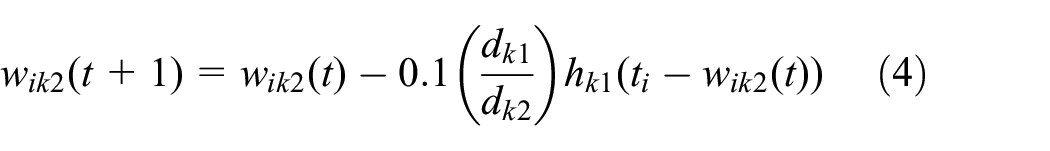
where
The mid-plane of k1 and k2 is defined as follows

where the value of w is between 0.2 and 0.3. For instance, if
Consequently, the LVQ NN learning algorithm has a higher recognition rate in each and every training sample set.
Intelligent lower-limb prosthesis control system
Structure description
Figure 2 shows the structural diagram of the intelligent lower-limb prosthesis control system. This control system consists of four components, namely, a lower-limb prosthesis and prosthetic socket, a sports biomechanics information acquisition system, a knee-joint damper regulator, and a control computer. The sports biomechanics information acquisition system is composed of an EMG signal sampler, a plantar pressure sampler, and an acceleration signal sampler.
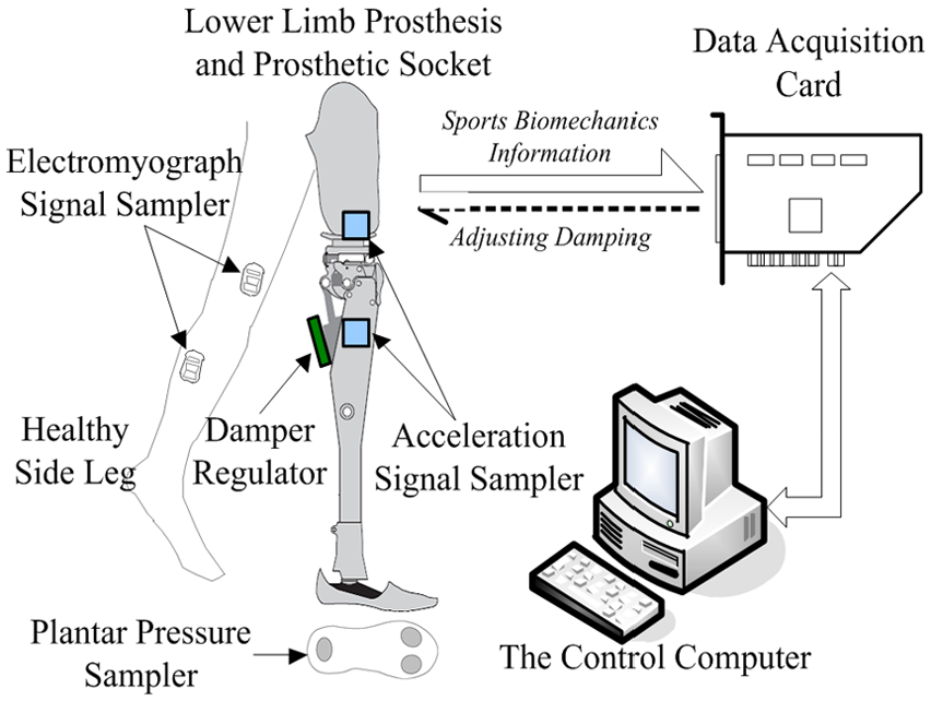
Structural diagram of the intelligent lower-limb prosthesis control system.
Figure 3 shows the intelligent lower-limb prosthesis prototype. A single-axis knee joint is utilized as its damper system, and a knee-joint damper cylinder is installed to drive this prosthetic knee joint and regulate its swing frequency and speed. Figure 4 shows the knee-joint damping cylinder, which is composed of a cylinder body, a piston rod, a needle valve, and a stepper motor. Therefore, the stepper motor is utilized to drive the needle valve, change the valve opening, and regulate the corresponding damping moment when the piston rod moves in the cylinder. Regulation and control of the damping moment is implemented by changing the motor patterns of the stepper motor or by controlling a microstepper motor to change the valve opening of a valve inlet loop or a check valve. The damping regulation algorithm combines the sensor data and the recognition results of lower-limb prosthesis motor patterns to determine the current angle position of the stepper motor. This approach regulates the damping moment of a cylinder. The total mechanical travel of this cylinder valve opening is 422 steps.

Intelligent lower-limb prosthesis prototype.

Knee-joint damping cylinder to drive the prosthesis.
Figure 5 shows the EMG signal sampler. Safe and noninvasive surface electrodes are utilized to detect the EMG signals of the skin surface. Two signal processing circuits are added to eliminate external interferences. A low-noise signal line is required to connect the sensor probe and the secondary signal processing circuit. Finally, the processed signal can be transmitted to the control computer using a data acquisition card or other special instruments. The wavelet transform method is also considered in the control computer to further eliminate noise interference. In this control system, MyoTrace 400 EMG Signal Acquisition Instrument is selected to gather and analyze the EMG signals and connect with the control computer.

EMG signal sampler for lower-limb muscles information.
Figure 6 shows the plantar pressure sampler. The polyvinylidene fluoride (PVDF) thin-film force sensors are utilized to detect the plantar pressure and obtain the contact conditions of the plantar and ground. Three PVDF force sensors are placed in the heel and toe areas of the lower-limb prosthesis. Their output signals are further amplified and transmitted to the control computer through the data acquisition card.

Plantar pressure sampler for contact information of feet and ground.
Figure 7 shows the acceleration signal sampler. A dual-axis accelerometer is required to acquire the lower-limb angle information, including the angle of the thigh and horizontal plane, the angle of the calf and horizontal plane, and the flexion angle and angular velocity of the knee joint. Four dual-axis accelerometers are placed in the thighs and calves of both the prosthetic side leg and the healthy side leg. In this control system, the ADXL203 dual-axis accelerometer is selected and connected to the data acquisition card.

Acceleration signal sampler for lower-limb angle information.
In this control system, two kinds of software are used, namely, MyoResearch-XP and LabView-based information collecting software. MyoResearch-XP is a special software for EMG signals that matches with MyoTrace 400. And LabView-based information collecting software is self-developed to collect, analyze, and record information from the data acquisition card, including plantar pressure and acceleration information.
Control description
Figure 8 represents the control block diagram of the intelligent lower-limb prosthesis. The control system is divided into three layers. Several sports biomechanics signals are sampled in the first layer. In the second layer, the movement pattern and gait of the wearer are recognized. A LVQ NN control model is then built as the controller, because the acquired sports biomechanics signals are used as the input variables. In the third layer, the input variable of the knee-joint damping cylinder is obtained from the controller output. Control of the damping moment is then implemented.

Control block diagram of the intelligent lower-limb prosthesis system.
Movement pattern and gait recognition
To ensure that the prosthetic limb tracks the healthy limb, the movement pattern of the healthy lower limb should be accurately recognized. This method is effective for examining the EMG signals of lower-limb muscles.6,23 In our prosthesis system, four thigh muscles, namely, vastus medialis oblique (VMO), semitendinosus, adductor longus, and tensor fasciae latae are selected.
Gait phases change even if a person always maintains a movement pattern. Thus, gait recognition is also required in the implementation of precise prosthetic control. For example, Figure 9 shows the gait phase changes of the right foot in a gait cycle during level walking. As shown, level walking consists of five gait phases. The EMG signals, plantar pressure signals, and lower-limb angles differ at each gait phase.

Gait phase changes of the right foot in a gait cycle during level walking.
Figure 10 shows the signal curves in a gait cycle during level walking. In the figure, the first four curves represent the EMG signals, P1–P3 represent the plantar pressure signals of different positions, and

Signal curves in a gait cycle during level walking.
LVQ NN-based MRAC method
MRACS is an important branch of the NN-based adaptive control system. 17 The steps for designing MRACS are as follows. First, an appropriate reference model system and an adaptive algorithm obtained through stability theory are selected. Second, the error signals between the outputs of the reference model system and a real system are then calculated. Third, with the selected adaptive algorithm, these error signals are converted into the current controlled quantity to control the real system adaptively. Converting the performance indices in MRACS is unnecessary. Therefore, MRACS is easy to design and can adapt rapidly.18,23
Structure of LVQ NN-based MRACS
Figure 11 shows the structure of NN-based MRACS. This control system consists of two NNs, namely, NN1 and NN2. NN1 refers to a recognition model network used to recognize motor patterns. It is trained by the angle information of the knee joint. An object recognition model is then built online with the regression algorithm to enable NN1 to predict the outputs of the controlled object or the knee-joint damper. NN2 refers to a controller network, which is used to match the outputs of the reference model and object recognition models by regulating the inputs of the controlled object. The reference model refers to an ideal system model between the reference input and output of the controlled object, which has a certain structure and constant parameters. TDL refers to the tapped delay line.

Structure of the NN-based model reference adaptive control system.
In this model, r is the reference input, ym is the desired output of the reference model, yp is the practical output of the controlled object, u is the control signal produced by NN2, e1 is the error between yp and the output of NN1, and e2 is the error between yp and ym. In addition, e1 is used to adjust the parameters of NN1 and e2 is used to adjust the parameters of NN2.
The aim of NN-based MRACS is to ensure that the errors between the outputs of the controlled object and the reference model are under the same input within a given accuracy range. This condition can be described by equation (6)

where
These two NNs belong to the LVQ NN, because the boundary of each class is accurately defined by the relationship information of input classes. The probability of misrecognition is thus effectively reduced.
Establishment of NN-based object recognition model
The two LVQ NNs shown in Figure 8 are composed of three layers, namely, input, competitive, and output layers. The number of neurons in each layer and the learning time are selected according to learning experience. In this experiment, the structure of NN1 is (13, 20, 6) and the learning time is equal to 250. The structure of NN2 is (19, 35, 6), and the learning time is equal to 400. The transfer function of the output layer is linear. The initial learning rate in each experiment is equal to 0.03 and control accuracy

NN-based object recognition model.
The model reference controller module in Figure 12 is concretely implemented similar to Figure 13, which refers to the concrete implementation of NN1 in Figure 11.

Model reference controller module.
In Figure 13, NN controller and NN plant refer to NN2 and NN1 in Figure 11, respectively. r and u have the same meanings in both Figures 11 and 13. And y refers to yp.
Experiment results and analyses
Experimental description
To verify the proposed NN-based MRACS in Figure 11, the intelligent lower-limb prosthesis is investigated under different movement patterns. The tested movement patterns consist of level walking, jogging, stair ascent and descent, and standing and sitting. To examine its dynamic performances, the transformation processes from level walking to another movement pattern are also tested. Figure 14 depicts the experiments of the intelligent lower-limb prosthesis.

Experiments of the intelligent lower-limb prosthesis.
To test the gait symmetry performance of the prosthesis, experiments are also conducted wherein a tester walks at different speeds with or without the prosthesis.
In these experiments, the lower-limb prosthesis is the research object, and it is controlled by regulating the knee-joint damping moment. The EMG, pressure, and angle signals are sampled at 50, 1000, and 200 Hz, respectively. Each trial is performed by the same tester and finished within 1–2 min. Before each trial, a healthy tester is asked to wear the prosthesis and undergo training for 10–15 min.
Evaluation indexes
In the experiments under different movement patterns, recognition accuracy is considered an evaluation index. Movement pattern recognition accuracy and gait recognition accuracy during certain movement pattern are also tested.
Gait tracking time is another evaluation index. It represents the time of recognizing the changed gait and executing the control command when the gait changes. In the prosthesis system, the sampled lower-limb signals are transmitted and processed in the data frame. A control command is used as the output for the knee-joint damping cylinder.
Figure 15 shows the schematic of gait tracking time, wherein


Schematic of gait tracking time.
In the experiments at different speeds during level walking, the gait symmetry index is utilized to estimate the quality of gait motion, which is expressed as equation (8)
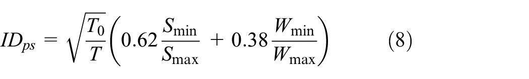
where
Results during two movement patterns
Only the experimental results of two typical movement patterns are shown in this article because of the space constraints. The two patterns are level walking and stair ascent.
Level walking is tested on a platform that requires a trained tester to wear the prosthesis and walk at 2 km/h. Figures 16–18 show the sampled EMG signals, plantar pressure signals, and acceleration signals in four continuous gait cycles. Figure 19 presents the corresponding gait phase recognition results. Figure 20 presents the corresponding control command for the needle valve position of the knee-joint damping cylinder.

Sampled EMG signals in four gait cycles during level walking.

Sampled plantar pressure signals in four gait cycles during level walking.

Sampled acceleration signals in four gait cycles during level walking.

Gait recognition results in four gait cycles during level walking.

Control command for the knee-joint damping cylinder in four gait cycles during level walking.
Stair ascent is tested on a three-step stair. The tester first uses his or her healthy leg followed by the prosthetic leg. Figures 21–23 depict the sampled lower-limb signals in three continuous gait cycles. Figure 24 presents the corresponding gait recognition results, in which the gait of stair ascent only consists of leg lift and touchdown. Figure 25 presents the corresponding control command for the needle valve position of the knee-joint damping cylinder. The experimental results of stair descent are not provided, because they are similar to those of stair ascent.

Sampled EMG signals in three gait cycles during stair ascent.

Sampled plantar pressure signals in three gait cycles during stair ascent.

Sampled acceleration signals in three gait cycles during stair ascent.

Gait recognition results for three gait cycles during stair ascent.

Control command for the knee-joint damping cylinder in three gait cycles during stair ascent.
The changes among the different movement patterns are also tested. Figures 26–28 show the sampled lower-limb signals when the movement pattern changes from level walking to stair ascent. Figure 29 presents the movement pattern and gait recognition results. The solid line represents the movement pattern and the dashed line represents the gait phase of a certain movement pattern. Figure 30 presents the corresponding control signal for the needle valve position.

Sampled EMG signals when the movement pattern changes.

Sampled plantar pressure signals when the movement pattern changes.

Sampled acceleration signals when the movement pattern changes.
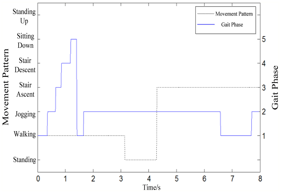
Movement pattern and gait recognition results when the movement pattern changes.

Control command for the knee-joint damping cylinder when the movement pattern changes.
According to the experimental results for the different movement patterns, gait recognition accuracy is 100%. Moreover, the accuracy of movement pattern recognition accuracy is 97.1% when the tester changes his or her movement pattern. Thus, the intelligent lower-limb prosthesis can achieve accurate movement recognition. In addition, the gait tracking time is 13.33 ms. Giving way or tripping does not occur, which confirms that the prosthesis system has a fast dynamic tracking performance and good supporting stability.
Results at different walking speeds
Figure 31 presents the angle positions of the two thighs when the tester wears the prosthesis and walks at 2 km/h. The solid line represents the angle position curve of the healthy thigh, and the dashed line represents the angle position curve of the prosthetic thigh.
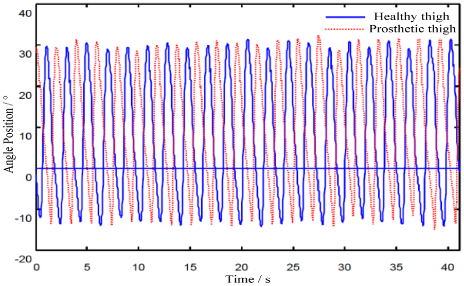
Angle positions of the two thighs when the tester wears the prosthesis and walks at 2 km/h.
Figure 31 has 20 gait cycles. Figure 32 shows the gait symmetry index of each gait cycle, with an average of 0.9109.

Gait symmetry index when the tester wears the prosthesis and walks at 2 km/h.
Figure 33 presents the angle positions of the two thighs when the tester wears the prosthetic limb and walks at 4 km/h. The two lines have the same meanings as those in Figure 31.
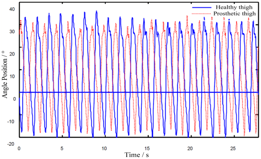
Angle positions of the two thighs when the tester wears the prosthesis and walks at 4 km/h.
Figure 33 also has 20 gait cycles. Figure 34 shows the gait symmetry index of each gait cycle, with an average of 0.9097.

Gait symmetry index when the tester wears the prosthesis and walks at 4 km/h.
Figure 35 presents the angle positions of the two thighs when the tester walks at 4 km/h without the prosthesis.

Angle positions of the two thighs when the tester walks at 4 km/h without the prosthesis.
Figure 35 also has 20 gait cycles totally. And Figure 36 shows the gait symmetry index of each gait cycle, with an average of 0.9317.

Gait symmetry index when the tester walks at 4 km/h without the prosthesis.
The thigh angles in Figures 31–36 fluctuate at a small range. Better gait symmetry performance is achieved when a healthy tester walks without the prosthesis than when the prosthesis is worn. The gait symmetry index is maintained at more than 0.90 when the tester walks at different speeds with the prosthesis. This finding means that the prosthetic limb features a good symmetry and feasibility.
Conclusion
The LVQ NN-based MRAC method for intelligent lower-limb prostheses succeeds in allowing the prosthetic limb to follow the healthy leg. The following conclusions were obtained from this study.
The proposed method implements accurate control of a prosthetic limb under different motor patterns and provides a reference for research on biped robots.
The method does not require the conversion of performance indexes. Thus, the corresponding control system is easy to design and can adapt rapidly.
Hysteresis exists in the designed control system. Thus, decreasing the delay time and improving the tracking precision require further research.
Footnotes
Academic Editor: Yaguo Lei
Declaration of conflicting interests
The author(s) declared no potential conflicts of interest with respect to the research, authorship, and/or publication of this article.
Funding
The author(s) disclosed receipt of the following financial support for the research, authorship, and/or publication of this article: This work is supported by the National Natural Science Foundation of China (61372023).