
Abstract
Fatigue failure is a serious problem in hydraulic piping systems installed in the machinery and equipment working in harsh operational conditions. To alleviate this problem, health monitoring of pipes can be conducted by measuring and analysing vibration-induced strain. Fibre Bragg grating is considered as a promising sensing approach for dynamic load monitoring. In this article, dynamic strain measurements based on fibre Bragg grating sensors for small-bore metal pipes have been investigated. The quasi-distributed strain sensing of fibre Bragg grating sensors is introduced. Two comparison experiments were carried out under vibration and impact loads among the methods of electrical strain gauge, piezoelectric accelerometer and fibre Bragg grating sensor. Experimental results indicate that fibre Bragg grating sensor possesses an outstanding ability to resist electromagnetic interference compared with strain gauge. The natural frequency measurement results, captured by fibre Bragg grating sensor, agree well with the modal analysis results obtained from finite element analysis. In addition, the attached fibre Bragg grating sensor brings a smaller impact on the dynamic characteristics of the measured pipe than the accelerometer due to its small size and lightweight. Fibre Bragg grating sensors have great potential for the quasi-distributed measurement of dynamic strain for the dynamic characteristic research and health monitoring of hydraulic system pipeline.
Keywords
Introduction
Hydraulic pipes have a wide range of applications in machinery and equipment. However, pressure fluctuation and pipe vibration may induce fatigue failures.1,2 Online load monitoring of hydraulic system pipeline is an effective method to prevent the breakdown of equipment. 3 It is essential to acquire multi-point and real-time strain responses of pipes caused by internal and external dynamic loads to analyse fatigue properties and detect potential damages. 4 Although electrical strain gauges and piezoelectric accelerometers are traditional choices for load monitoring of hydraulic system pipeline, their wirings and electromagnetic interference (EMI) from the equipment pose significant challenges for deployment and multi-point accurate measurement. Unlike the conventional approach, fibre optical sensor has been emerging as an increasingly important tool for machine’s operating condition monitoring due to its unique advantages in sensitivity and multiplexing capability. Moreover, one optic fibre can enable tens of fibre optic load sensors to multiplex, thus greatly lessening the wiring issue. 5 Using light as sensing signal, fibre optical sensor is completely impervious to EMI.
As one of the most popular fibre optical sensor technologies, Fibre Bragg Grating (FBG) possesses a series of advantages over conventional electrical and piezoelectric sensors, such as small size, lightweight, explosion proof, chemical stability, flexibility, EMI immunity and quasi-distributed measurement.6–8 Over several decades, FBG sensing technology has been intensively studied and widely implemented in many fields.9–12 Structural health monitoring (SHM) based on FBG sensing technology is potentially an effective method to assess the integrity of a given structure, increase operational lifetime and reduce maintenance cost.13–15 For example, FBG sensors have been embedded in aircraft composite structures to monitor the vital locations of damages.16,17 In recent years, condition monitoring of wind turbine using FBG sensor technology has been significantly investigated. 18 Although utilizing FBG sensors for load measurement and condition monitoring is becoming increasingly common, the comparative investigations with conventional tools, such as electrical strain gauge and piezoelectric accelerometer, have only been marginally explored. 19
An FBG sensor can be easily attached on the surface of pipes with little effect on their dynamic characteristics, since its size and weight are diminutive. Furthermore, this kind of sensor is suitable for networking, which can be highly multiplexed, operating in inflammable and serious EMI environment. Therefore, FBG strain sensor was adopted to detect the leakage of natural gas pipeline by measuring strain of pipeline caused by negative pressure wave. 20 FBG hoop-strain sensor was designed to monitor pipeline corrosion. 21 The response measurement by full-term FBG sensors was applied for the health monitoring of submarine pipeline. 22
In this article, dynamic strain measurements using FBG sensors for hydraulic system pipes have been investigated. This article will firstly give a brief introduction to quasi-distributed strain sensing of FBG sensors. Then, comparison experiments under vibration and impact loads are imposed for strain gauge, piezoelectric accelerometer and FBG sensor. FBG sensors are utilized for multi-point strain measurement of the tested pipe to acquire its dynamic characteristics. Experimental results have been provided and discussed. The experimental results indicate that FBG sensors are expected to be used to measure the vibration-induced dynamic strain for the dynamic characteristic research and health monitoring of hydraulic system pipeline.
Quasi-distributed strain sensing
FBG sensors are basically strain-measuring devices and provide the superior advantages of strain-measuring principle, making them very suited to some special applications. FBG is encoded by optical wavelength information, making FBG sensor self-referencing and independent of fluctuating light levels. Large-scale multiplexing capability could enable FBG sensors with the ability to sense quasi-distributed strain along pipelines.
Fundamental of FBG sensing
FBG is an intrinsic device with periodic modulation of the refractive index in the core of an optical fibre, written by exposing the core to an intense interference pattern. With cladding diameter of 125 µm, the optical fibre is small size and lightweight, suitable for being embedded into or attached to a structure.
When spectral broadband light is coupled into optical fibre, a particular narrow wavelength band would be reflected back by FBG in the fibre. 23 The peak wavelength of the reflected light is called Bragg wavelength λB, which is defined by 4

where neff is the effective refractive index of the core material and Λ is the grating period. Bragg wavelength shift Δλ of an FBG response to strain (ε) and temperature change (ΔT) is given by 24

where λ0 is the initial Bragg wavelength of an FBG, and pe and αδ are the photo-elastic coefficient and the change of refraction index, respectively. To address the cross-sensitivity problem which exists in strain measurement, an additional temperature-measuring FBG is usually adopted as temperature compensation for the strain-measuring FBG. 25
Multiplexing possibility of FBG sensing
Multiplexing of FBG sensors is one of the most effective approaches to simplify sensor system and reduce installation and operation cost for multi-point strain measurement. Multiplexing technologies, such as Time Division Multiplexing (TDM), Wavelength Division Multiplexing (WDM) and Space Division Multiplexing (SDM), enable FBG sensors to realize quasi-distributed and remote stain measurement and simultaneous demodulation of sensing information from multi-points along the pipeline in hash operating environments. Figure 1 shows a typical FBG sensor multiplexing system, which consists of broadband light source, wavelength monitoring device, coupler, optical switch, FBG sensor arrays, signal processing, and analysis and output unit. Tens of FBG sensors can be written into one optical fibre and interrogated by one multi-channel instrument. The cable mass and volume of FBG sensors can be greatly reduced, which is very important for the complex hydraulic system pipes.
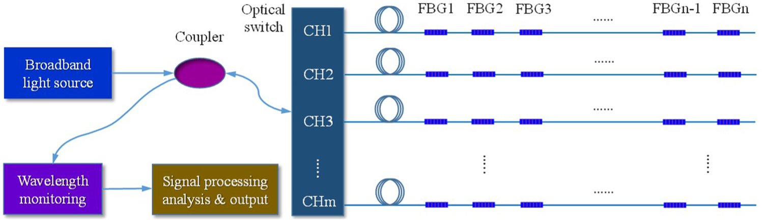
FBG sensor multiplexing system.
Experimental setup
To investigate dynamic strain measurement performance of FBG sensors, comparison experiments among strain gauge, piezoelectric accelerometer and FBG measurement methods have been carried out under vibration and impact loads. Finite Element Analysis (FEA) for modal analysis of the tested pipe has been employed in the impact experiment to provide a reference for the FBG sensor measurement result.
Strain measurement under vibration exciting load
The experimental setup of vibration testing experiment of pipe is depicted in Figure 2. It consists of a straight metal pipe, strain gauge, FBG sensor, power amplifier, vibrator, waveform generator, FBG interrogator, laptop and so on. The FBG sensor was installed on the surface of the tested pipe to monitor the vibration-induced strain. For comparison purpose, a strain gauge was attached closely to FBG sensor. The installation positions of FBG sensor and strain gauge were both near to the fixed point of the tested pipe, as shown in Figure 2. The tested pipe was clamped on the vibrator and excited by a sinusoidal force. The excitation was provided by the vibrator, power amplifier and waveform generator (Rigol DG1022U). A dynamic FBG interrogator with highest sample rate of 4 kHz was used to detect the wavelength shift of FBG sensor in real-time. The FBG interrogator was based on the tunable Fabry–Perot (FP) filter technology with a minimum resolution of 1 pm. A high-speed data acquisition device was utilized for the strain gauge.

Experimental setup and installation positions of sensors.
The main parameters of the tested pipe are presented in Table 1. The frequency of the exciting force is set as 200 Hz with an acceleration of 110 m/s2. The data acquisition rates of the FBG sensor and strain gauge are both at 4 kHz in the vibration experiment.
Pipe parameters.

Strain measurement under impact load
The schematic representation of the impact experimental setup is shown in Figure 3. 26 An FBG sensor was placed on the surface of pipe to monitor the dynamic strain under an impact load excited by an impact hammer. At the same time, a piezoelectric accelerometer (4.8 g) was used to measure the dynamic response of the tested pipe. The tested pipe was filled with non-pressure water with two ends plugged and hung by elastic ropes at two points. During the impact experiment, both the FBG sensor and piezoelectric accelerometer responses were acquired at a rate of 4 kHz.

Schematic representation of the impact experiment setup.
Before impact test, modal analysis of the tested pipe was carried out by FEA using the ANSYS software. The three-dimensional (3D) geometry model with mesh of the tested pipe is shown in Figure 4. The boundary conditions of the tested pipe were free. The water in the pipe was considered as added mass in the pipe in the simulation calculation. The material of the tested pipe is 1Cr18Ni9Ti with a density of 8030 kg/m3. The wall thickness and inner diameter of the pipe are 15.50 and 1.19 mm, respectively. Young’s modulus and Poisson’s ratio are considered as 193 GPa and 0.31, respectively. The density and bulk modulus of the water in the tested pipe are 997 kg/m3 and 2.2 GPa, respectively.

3D geometry model with mesh.
Multi-point strain measurement
As shown in Figure 5, FBG sensors were employed to detect multi-point strain responses of the tested pipe to investigate its dynamic characteristics. The experimental setup consists of pump, hydraulic oil tank, hydraulic valves, FBG interrogator, vibrators, pipe, FBG sensors and so on. A total of 12 FBG sensors were installed on the surface of the tested pipe along length direction to measure vibration strain responses. The tested pipe was filled with pressure hydraulic oil and clamped on the vibrators at two points. The pipe was excited by a sin sweep frequency force from 5 to 1000 Hz by the vibrators.
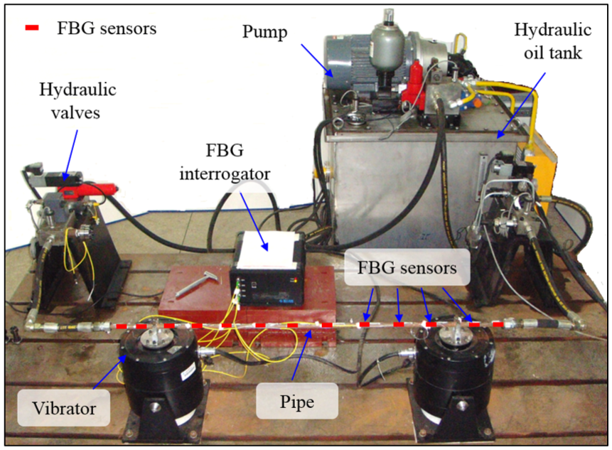
Experimental setup of multi-point strain measurement.
Results and discussion
Vibration exciting experiment
The results of dynamic responses of the tested pipe measured by FBG sensor and strain gauge are shown in Figure 6. The vibration strain signals measured by FBG sensor and strain gauge within 0.20 s are shown in Figure 6(a) and (c), respectively. Figure 6(b) and (d) calculated by Fast Fourier Transform (FFT) algorithm are the frequency spectrums of the strain signals measured by FBG sensor and strain gauge, respectively.
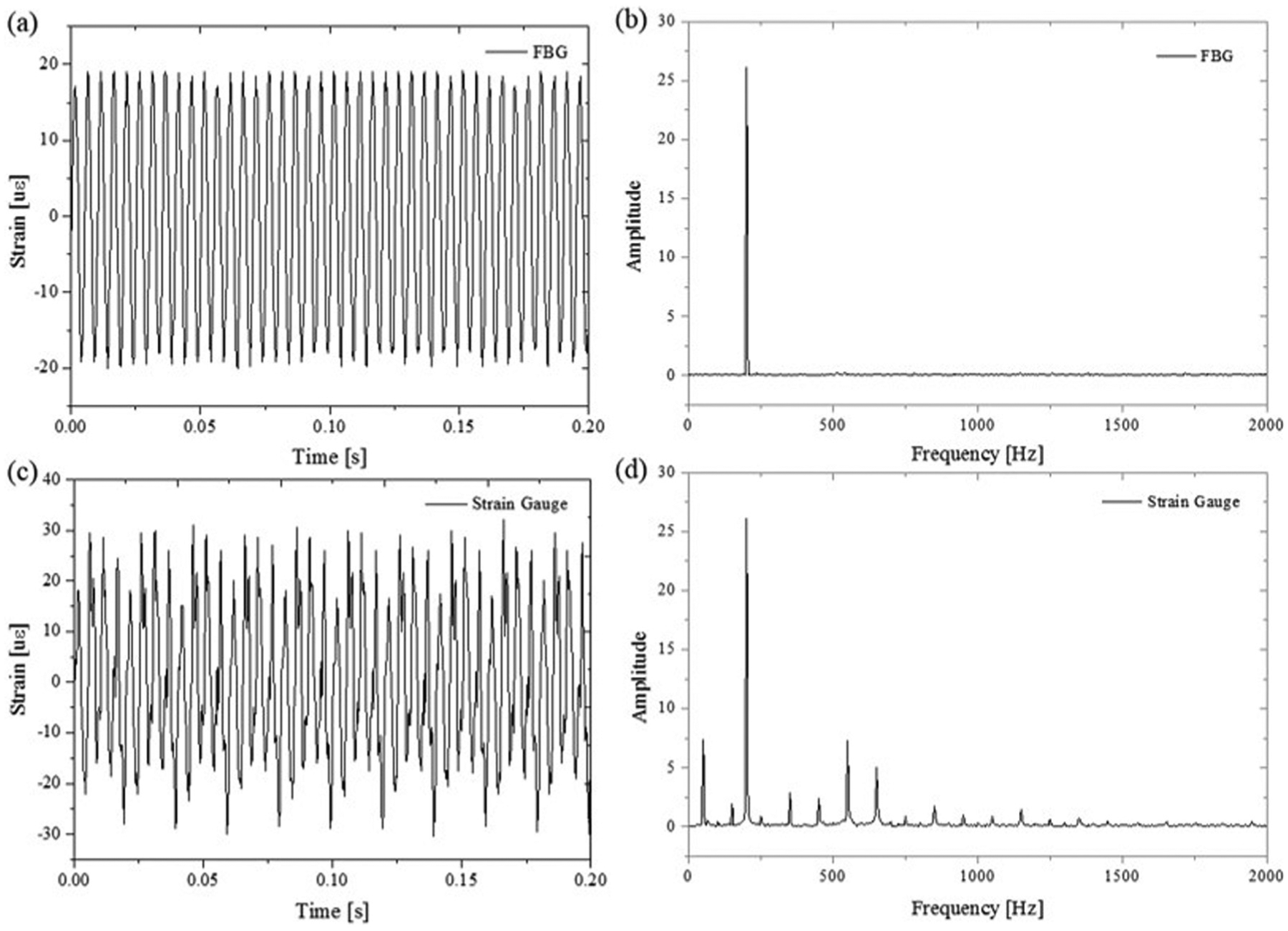
Dynamic responses. (a) Strain signal and (b) the frequency spectrum measured by FBG sensor. (c) Strain signal and (d) the frequency spectrum measured by strain gauge.
As shown in Figure 6(b) and (d), the frequency signal of exciting force with a frequency of 200 Hz is clearly captured by both FBG sensor and strain gauge. It could be found that there is little noise signal in the strain signal measured by FBG sensor in Figure 6(b), while there are many noise signals in the results measured by strain gauge as shown in Figure 6(d). As shown in Figure 7, the measured result by the strain gauge has the same frequency noise signal without excitation applied on the pipe. The noise signal comes from the nearby electromechanical devices in the laboratory. The experimental results indicate that FBG sensor possesses a more outstanding ability to resist EMI than strain gauge, especially in harsh EMI environment.

Frequency spectrum comparison with excitation and without excitation.
Strain measurement under impact load
The vibration response results measured by FBG sensor within 1.5 s under impact load excited by an impact hammer are shown in Figure 8. The strain signals of the tested pipe without an accelerometer on its surface and with one are shown in Figure 8(a) and (c), respectively. The related frequency spectrums of strain signals calculated by FFT algorithm are shown in Figure 8(b) and (d). The first five order natural frequencies of the tested pipe measured by FBG sensor under the two different situations are shown in Figure 8(b) and (d), respectively.
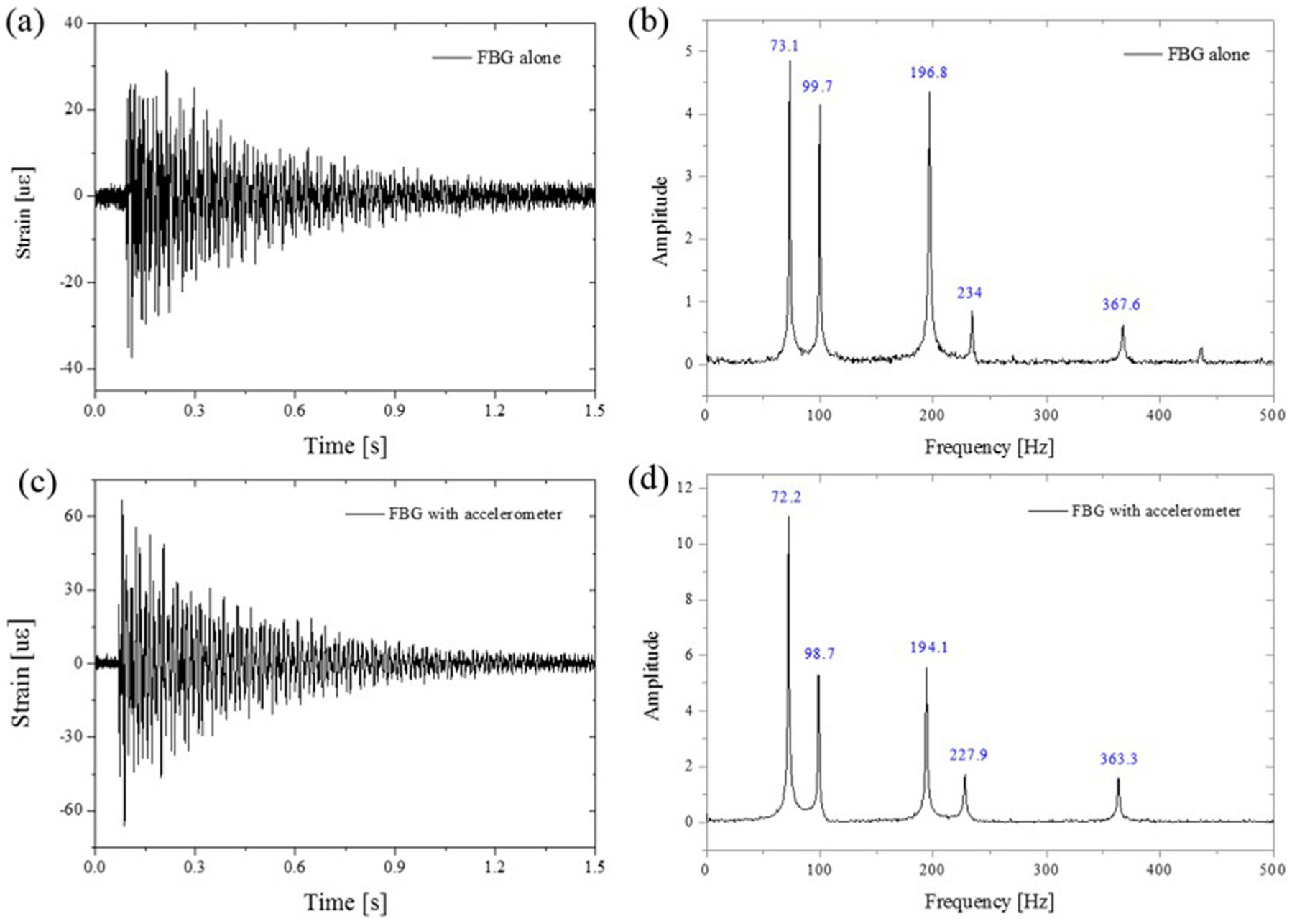
(a) FBG strain response without an accelerometer on the tested pipe and (b) its frequency spectrum, and (c) FBG strain response with one and (d) its frequency spectrum.
Figure 9 illustrates the first five order natural frequencies calculated by FEA and measured by FBG sensor and accelerometer. Figure 9(a) demonstrates that the measurement results of FBG sensor agree better with results calculated by FEA considering the calculation error than the results measured by accelerometer. The natural frequency measured by FBG sensor with an accelerometer installed on the surface of tested pipe and without one is shown in Figure 9(b). As the differences of the measured first five order natural frequencies are all negative in Figure 9(b), it shows that the values of the first five order natural frequency measured by FBG sensor with an accelerometer on the tested pipe are all smaller than those without one. It could be found that although the weight of the accelerometer (approximate 4.8 g) is small, it still brings an effect on the dynamic characteristics of measured pipes and the attached FBG sensor brings a smaller impact on dynamic characteristics of measured pipes.

(a) Natural frequency calculated by FEA and measured by FBG sensor and accelerometer, and (b) the natural frequency measured by FBG sensor with an accelerometer on the surface of tested pipe and without one.
Multi-point strain measurement results
Figure 10(a) shows the strain response results measured by FBG sensors 4, 7 and 10 within 1.2 s. The frequency spectrums of the 12 strain signals are calculated using FFT algorithm, which are illustrated in Figure 10(b). According to Figure 10(b), the first five order natural frequencies (15.1, 100.9, 435.9, 543.6 and 786.7 Hz) of the tested pipe could be obtained. Moreover, the related stain mode shapes and damping ratios of the tested pipe can be calculated by the strain measurement results of the 12 FBG sensors. The experimental results show that FBG sensors have great potential for the quasi-distributed measurement of dynamic strain for the dynamic characteristic investigation of hydraulic system pipeline.
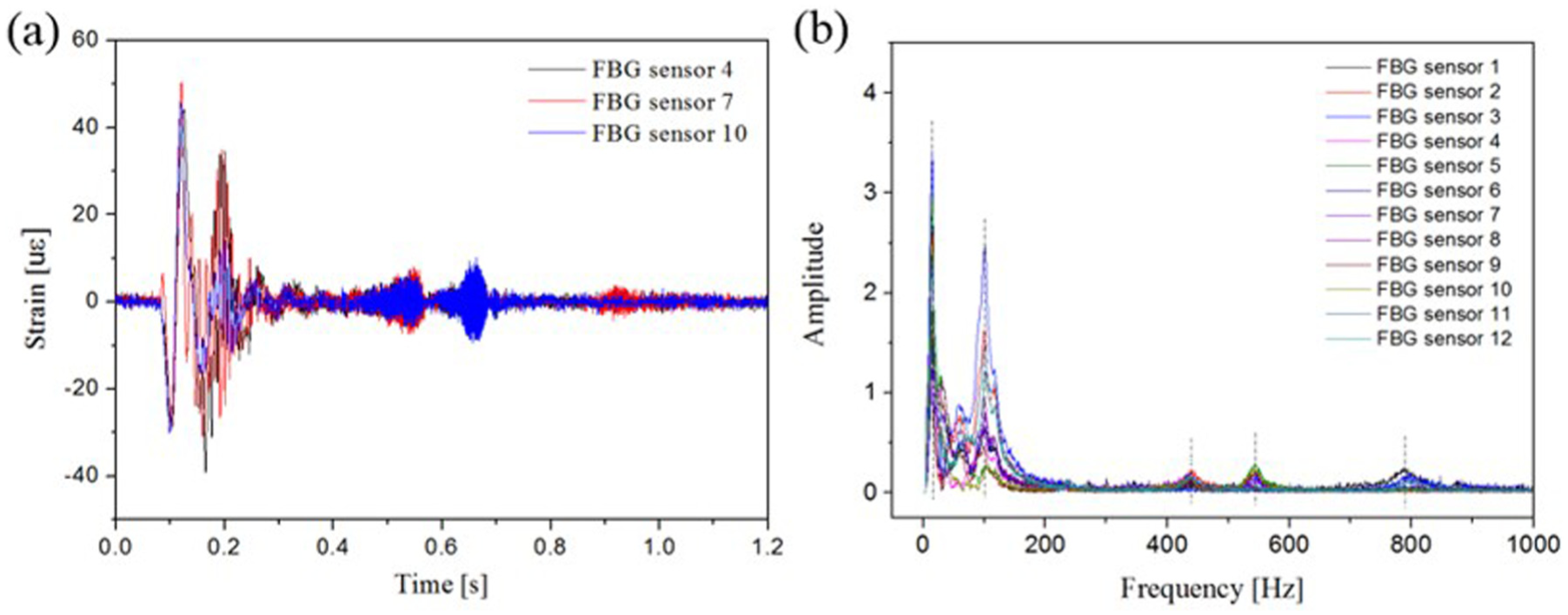
(a) Strain responses and (b) frequency spectrums measured by FBG sensors.
Conclusion
In hydraulic piping system, vibration-induced stress monitoring of pipes is essential to prevent potential fatigue failures in machinery and equipment. The unique advantages of FBG sensors have strongly established their place for the dynamic response measurement of hydraulic system piping. In this article, the quasi-distributed strain sensing of FBG sensors was introduced. The dynamic response measurement experiments under vibration and impact loads were carried out and the comparison among the strain gauge, FBG sensor and piezoelectric accelerometer were given. In addition, 12 FBG sensors were utilized to measure multi-point strain responses of the hydraulic pipe to investigate its dynamic characteristics. The experimental results indicate that FBG sensor has a better ability to resist EMI than strain gauge for strain measurement of pipes in harsh EMI environment. Unlike piezoelectric accelerometer, FBG sensor brings little external mass to the tested pipe and has almost no effect on the dynamic characteristics of the tested pipe. The FBG sensor is promising for quasi-distributed measurement of dynamic strain responses for the dynamic characteristic research and health monitoring of hydraulic system pipeline.
Footnotes
Academic Editor: Xiaotun Qiu
Declaration of conflicting interests
The author(s) declared no potential conflicts of interest with respect to the research, authorship, and/or publication of this article.
Funding
The author(s) disclosed receipt of the following financial support for the research, authorship, and/or publication of this article: This research was supported by the National Natural Science Foundation of China (grant no. 51475343), the National High Technology Research and Development Programme of China (863 Programme; grant no. 2015AA042101) and the Fundamental Research Funds for the Central Universities (grant no. 2015III003).