
Abstract
Artificial disc replacements (ADRs) are orthopaedic implants designed to replace degenerated intervertebral discs, a common aetiology of chronic back pain. ADRs which emulate the biomechanics of the natural disc promote the natural physiological kinematics, which is important for minimising postoperative deterioration of surrounding structures. By quantifying and comparing the displacements and strains within the ADR and the natural disc, target values can be established for future biomimetic ADR designs. However, measuring internal strain in these devices can be challenging. To this end, this study presents a novel application of fibre optic strain sensing through the use of fibre Bragg gratings. In this proof-of-principle study, an ADR model was fabricated with an embedded fibre optic sensor and subjected to physiological loads. The ADR model consisted of an elastomeric ring reinforced with Kevlar fibre. This simulated the annulus fibrosus (AF) of the natural disc and was left either filled or unfilled with an elastomeric material which simulated the nucleus pulposus (NP) of the natural disc. Fixation of the disc to artificial bone was achieved using three pins on the superior face and three pins on the inferior face of the ADR. Using wavelength division multiplexing of the fibre Bragg gratings, the hoop strain within the AF was monitored with a spatial resolution of 10 mm. Measurements revealed local strain concentrations around the fixation points and that the nucleated configuration increased circumferential strain in the AF by over 10 times for a given axial displacement. The measured strain asymmetry was correlated with lateral bending angle with an accuracy of ±0.5 degrees, which could be applied to tracking changes to the range of motion in load-controlled bending tests, for example. With further development, this technology has the ability to assess future designs during pre-clinical testing.
Keywords
Introduction
About 50%–80% of adults experience lower back pain at some point in their lifetime and in extreme cases this can impair their ability to perform everyday tasks. 1 The most common cause of lower back pain is lumbar disc degeneration. 2 When non-surgical techniques prove to be ineffective, a common surgical procedure involves fusing the vertebrae together but this has been shown to increase the stress on adjacent discs, which may lead to degeneration of nearby discs. 3 Artificial disc replacement (ADR) is an alternative treatment which can mitigate this issue (Figure 1(a)). However, due to material and design challenges, many ADRs do not reproduce the biomechanical behaviour of the natural disc, which often results in other complications. For instance, an excessively compliant disc may increase loads on surrounding joints, specifically the facet joints (Figure 1(b)), accelerating facet joint osteoarthritis.4,5 Hence, it is important that ADRs reproduce the biomechanics of the natural disc. Advances in manufacturing and materials now make it possible to develop biomimetic ADRs, which simulate the biomechanical behaviour of the disc more closely than current devices. Ideally, the ADR should mimic the conversion of axial force to circumferential stress in the annulus fibrosus (AF), as observed in the natural disc, which encourages isostatic contact with the adjoining bone, minimizing pain and risk of vertebral endplate fracture.6,7
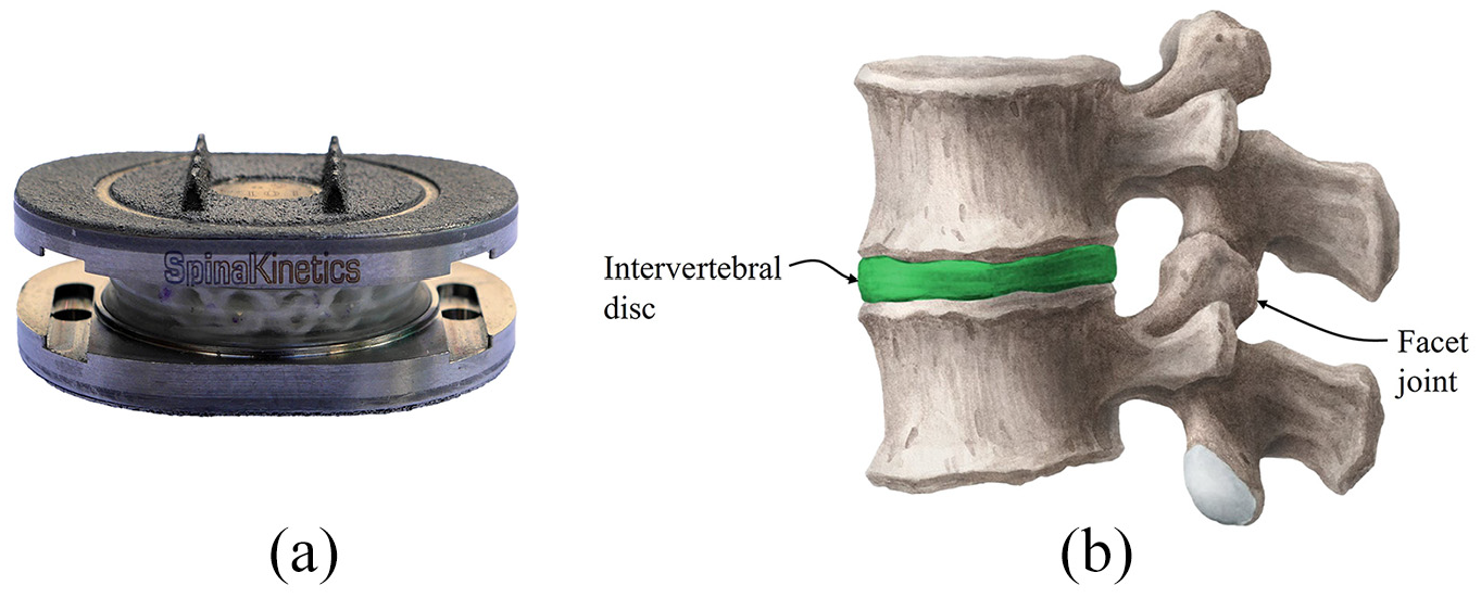
(a) An M6-L artificial disc replacement (ADR) manufactured by Orthofix (Texas, USA). (b) A functional spinal unit (FSU), which encompasses two vertebrae and the sandwiched disc. The facet joints on the posterior aspect of the spine contribute to the biomechanical behaviour of the motion segment.
Researchers often simplify biomechanical models of the spine by considering two vertebrae and the sandwiched disc. This assembly is referred to as the functional spinal unit (FSU). The biomechanical behaviour of the FSU is defined by the interaction between the disc and facet joints but most of the axial load in the spine is transferred through the disc. 9 It consequently plays a vital role in the spine’s performance and how vertebrates, in this case humans, interact with the world around them. The behaviour of the natural disc has been extensively studied but the biomechanics of the modified spine (e.g. due to disc arthroplasty), are dependent on the implanted device. Understanding how strain is distributed in and around the implanted device preclinically can help engineers design implants that safely interface with the vertebrae, minimising the risk of pain and further complications down the line.
Current methods of achieving this, such as strain gauges, digital image correlation (DIC), digital volume correlation (DVC) and finite element analysis (FEA) each offer advantages but also face limitations. Strain gauges are physically larger than a fibre optic cable, which increases the risk of affecting the structure, and suffer biocompatibility issues should the sensor be used in vivo. 10 Conventional strain gauges are unable to conform to a flexible structure. While biocompatible and flexible options are available,10,11 electrical-based systems are liable to inaccuracies when surrounded by a conductive medium (e.g. body fluids) and increasing spatial resolution is inherently more difficult than optical multiplexing, which can be done in a single sensing element – that is, a length of fibre optic cable. Imaging techniques such as DIC only measure surface strains but the principle can be extended to 3D imaging (DVC); however, this requires 3D imaging and a means of loading the implant accurately whilst achieving X-ray transmission (in the case of computed tomography). 12 This can present prohibitive costs and experimental complexity as well as time-dependency challenges due to the long scan times. FEA can offer detailed strain assessment but as predictions rather than measurement. 12
Alternative strain measurement techniques could help address these limitations if proven on representative models. It is proposed that optical sensing is one such technique. Optical sensors may take the form of a fibre optic cable (typically between 100 and 250

where
Although typically used in aerospace, automotive and civil engineering industries, FBGs have started showing great potential in various biomedical applications, from strain measurement in synthetic femurs to contact stress assessment in the hip and knee.16–27 Fibre optic sensing is well suited to these applications due to its biocompatibility, immunity to electromagnetic interference, small size and chemical inertness. 28
Specific to the intervertebral disc, FBGs have been used for intradiscal pressure measurement and disc bulge measurement. Intradiscal pressure measurement traditionally involves the use of needle transducers, typically over 1 mm in diameter,
29
which causes injury and disturbance to the disc.
30
The first attempt at developing a FBG pressure sensor for the intervertebral disc was by Dennison et al.
31
A fibre optic cable (125
Roriz et al. 34 attempted to measure disc bulge using an FBG but due to the fibre stiffness being far greater than the stiffness of the disc, it was not able to stretch as far as the disc. Learning from this work, two possible approaches to circumvent this issue would be to use a fibre optic cable with a lower stiffness or strategically position the cable such that its inherent stiffness provides minimal impact to the structure. The latter is investigated in this paper because high-quality gratings are difficult to inscribe into a low-stiffness (polymer) fibre optic cable and these types of fibres are more expensive than equivalent silica fibres.
This study aims to develop and assess an artificial AF instrumented with a circumferential fibre optic sensor. Note that the disc analogue used in this study was not designed to replicate the exact properties of the natural disc but aimed to promote the correct movements and strain distributions as a sensor demonstration platform. With the use of wavelength-division multiplexing, a spatially distributed hoop strain measurement technique is demonstrated that enables characterisation of the circumferential strains within an artificial AF. To provide additional context to the measurements, two configurations were tested: nucleated and denucleated. The interaction between the NP and AF is an important aspect of intervertebral disc function and is, therefore, a useful initial demonstration of sensor capability. Although axial compression is a key deformation mode, the kinematics of the FSU are defined by six degrees of freedom. The relationship between bending angle and sensor response was also considered in this study.
Materials and methods
Artificial disc manufacture
A disc analogue was required to test the viability of the proposed fibre optic sensor. The analogue was designed based on the biomimetic principle – a compliant matrix simulates the viscoelasticity of the natural disc and Kevlar fibre reinforcement generates the anisotropy observed in the natural disc, caused by collagen fibres. 7 Although this analogue was developed as part of a larger project to design a clinically applicable ADR, this particular configuration was not intended for clinical use.
The artificial AF was axisymmetric (40 mm OD, 25 mm ID, 10 mm thick) and manufactured from circumferentially wound Kevlar fibres embedded in a cast polydimethylsiloxane (PDMS) matrix. The mould assembly used to construct the AF is shown in Figure 2.
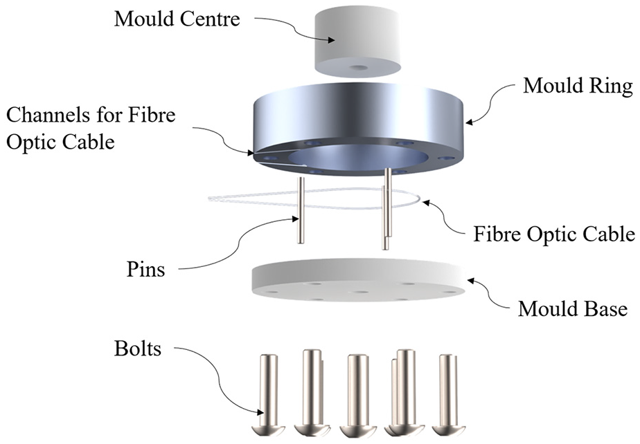
The casting mould was made from an aluminium ring and a polytetrafluoroethylene mould centre bolted to a polytetrafluoroethylene base plate. The pins shown in this diagram were for forming axial holes in the PDMS AF and are not the same pins used for implant fixation. The fibre optic sensor was introduced into the mould cavity through two oblique channels on the underside of the mould ring.
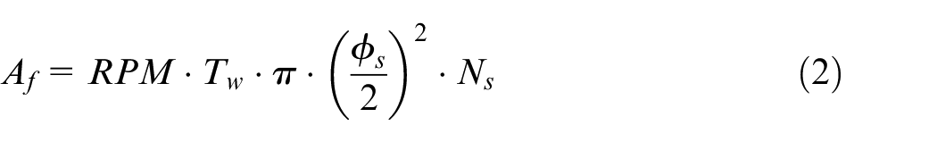
Initially, 11 m of Kevlar 49 aramid yarn (DuPont, Wilmington, DE, USA) was wound onto a mandrel to produce a fibre preform (Figure 3) which was placed into the mould. The yarn length was determined by controlling the rotating speed of the mandrel and timing the winding period. The total cross-sectional area of Kevlar embedded in the implant (
where,
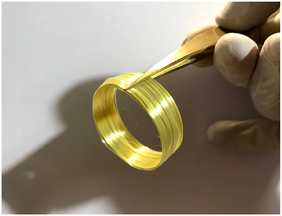
Kevlar fibre preform. This Kevlar preform was placed into the mould cavity, with the fibre optic sensor, to be embedded within PDMS.
The fibre was confined to a 1 mm thick layer of the AF positioned tangential to the outside of the pins. It follows that the fibre:matrix volume fraction within the fibre reinforced layer was 87%. Disc fixation during testing was achieved using three pins on each platen (on a 32.5 mm pitch circle diameter), which located in holes formed in the AF by the mould pins (Figure 2). The mould pins and fixation pins were made from 3 mm diameter precision ground high-carbon steel (BS-1407). The mould pins passed through the AF, to create three axial holes (Figure 2), whereas the fixation pins were pressed into the nylon platens, protruding by approximately 3 mm to engage with the moulded holes in the AF.
To reduce porosity and increase implant consistency, the casting process was performed under vacuum. Firstly, 11 ± 0.1 g of PDMS (MM228, ACC Silicones, Bridgwater, UK) was stirred for 3 min. The container was then attached to a servo motor which was placed inside a vacuum chamber. The mould containing the Kevlar preform was placed directly under the container of uncured PDMS such that when the servo motor was actuated, the PDMS was poured into the mould. This allowed separate degassing of the preform and PDMS under vacuum for 7 min before combining. After combining, the implant remained under vacuum for a further 15 min, after which the vacuum chamber was vented and the mould assembly transferred to an oven for initial curing for 2 h at 70 ± 10ºC. The AF was removed from the mould after 12 h at room temperature. A NP was cast from PDMS as a separate component and pressed into the cavity in the AF. The AF construction is shown in Figure 4(a).
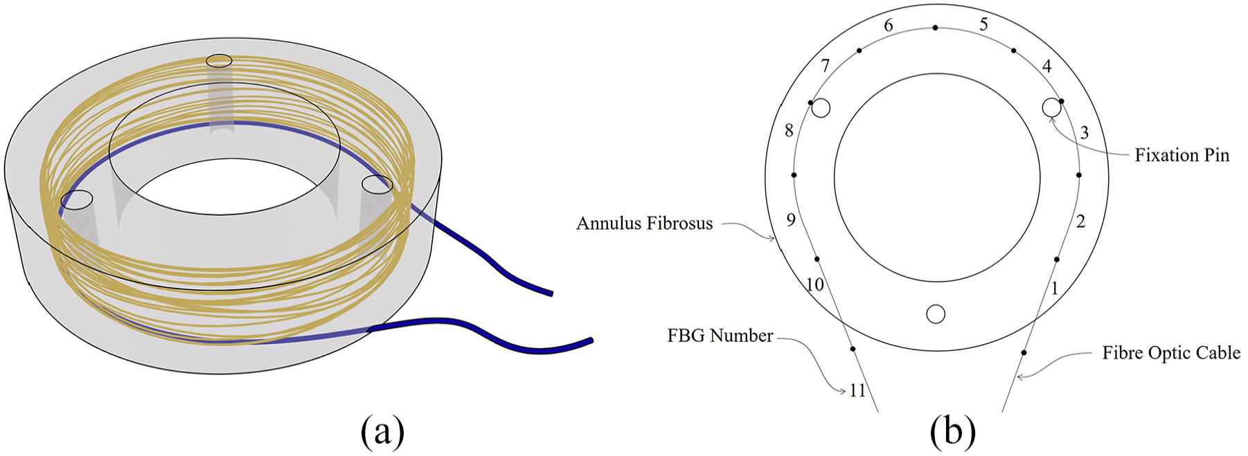
(a) The artificial AF comprising PDMS and embedded Kevlar reinforcement. The fibre optic cable (blue) follows the path of the Kevlar fibres (yellow), apart from near the ingress/egress point of the optical fibre. (b) Arrangement of the embedded fibre optic sensor including the position of each FBG. The fibre optic cable was placed tangential to the outside of the pins, in the radial centre of the Kevlar ring and close to the inferior face of the implant.
Fibre optic sensor
Direct ultraviolet writing was used to inscribe 11 adjacent FBGs (1495–1545 nm), each 10 mm long, into stripped single-mode fibre optic cable (GF4A). Direct ultraviolet writing uses a continuous-wave ultraviolet laser to alter the refractive index of ultraviolet-sensitive glass to form the Bragg gratings. 35 In this particular case, dual-beam ultraviolet writing was used. This involves overlapping two coherent laser beams, which form an interference pattern on the glass. The periodicity of the interference pattern defines the periodicity of the Bragg grating, which can be adjusted by changing the angle of the two laser beams. The laser beams are modulated and the fibre optic cable is translated at a speed synchronised to the modulation to generate the Bragg grating within the core of the optical fibre. The FBG inscription equipment was a custom set-up based on a frequency-doubled argon ion laser (244 nm). 36 10 gratings were embedded within the AF; the remaining grating was used as a reference grating for temperature compensation. All the FBGs were written into a single fibre optic cable, so their orientation relative to each other was automatically defined. During the writing process, the positions of the FBGs were marked with a fine-tipped pen, to help position the fibre optic cable in the implant during the embedding procedure. Vertically within the implant, the fibre optic sensor was embedded close to the inferior face to allow fibre ingress and egress. The grating positions are shown in Figure 4(b).
The fibre was recoated with acrylate (OP420632) to protect the fibre from micro-cracking during embedding and handling. An optical spectrum analyzer (AQ6317B, Ando, acquired by Yokogawa, Tokyo, Japan) combined with a wideband light source (Amonics, Hong Kong) was used for sensor interrogation.
It is useful to note that a custom fibre optic cable does not necessarily need to be fabricated for such experiments and there are various off-the-shelf options. Likewise, interrogation can be performed using a standard unit, making this characterisation approach accessible to facilities where optical engineering is not a speciality.
The spectrum analyzer output reflected power versus wavelength. Gaussian curves were fitted to the data points corresponding to each grating and the wavelength shifts were extracted from the peak shift of each Gaussian curve. No temperature compensation was included because the experiment was conducted in a temperature-controlled laboratory and was assumed constant during the experiment.
In many engineering applications, including the present study, converting from wavelength shift to strain is more relevant. Equation (3) was used to convert the wavelength shift to strain (
where,
where,
Mechanical testing
A test rig was designed and constructed based on Standard ASTM F2346 38 to fit an Instron Electropuls E10000 test machine. The fixture (Figure 5) comprised a universal joint attached to the actuator, to which a bar was attached. A bronze concave hemispherical end to the bar mated against a stainless steel convex component. Vertebrae analogues (or platens), which sandwiched the ADR, were made from nylon. The upper platen was fixed to the underside of a micrometer stage and the convex component was bolted to the top of the micrometer stage. The radius centre of the convex component was situated in the centre of the ADR. This allowed rotation of the upper platen relative to the lower platen, which was fixed to the load cell, which in turn was bolted to the machine bed. The micrometer stage enabled lateral, or anterior-posterior movement of the convex stainless steel component relative to the upper platen, depending on the chosen orientation of the stage. Translation of the micrometer stage induced a bending displacement on the implant (Figure 6). Note that the micrometer stage is a modification to the standard. 38 The relationship between the stage offset and applied bending angle is given in equation (5).
where
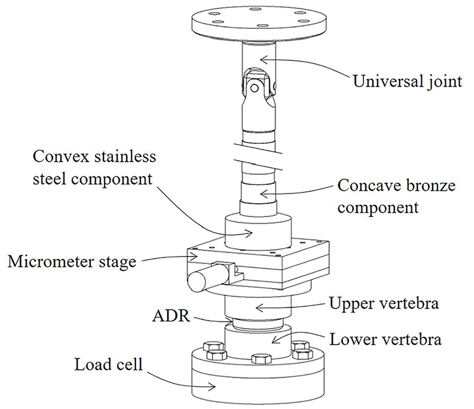
The fixture fitted into the test machine to apply loading to the ADR in accordance with ASTM F2346. 38 The micrometer stage is a modification to the standard and generates a load offset which subjects the implant to bending. Increasing this offset increases the bending angle.
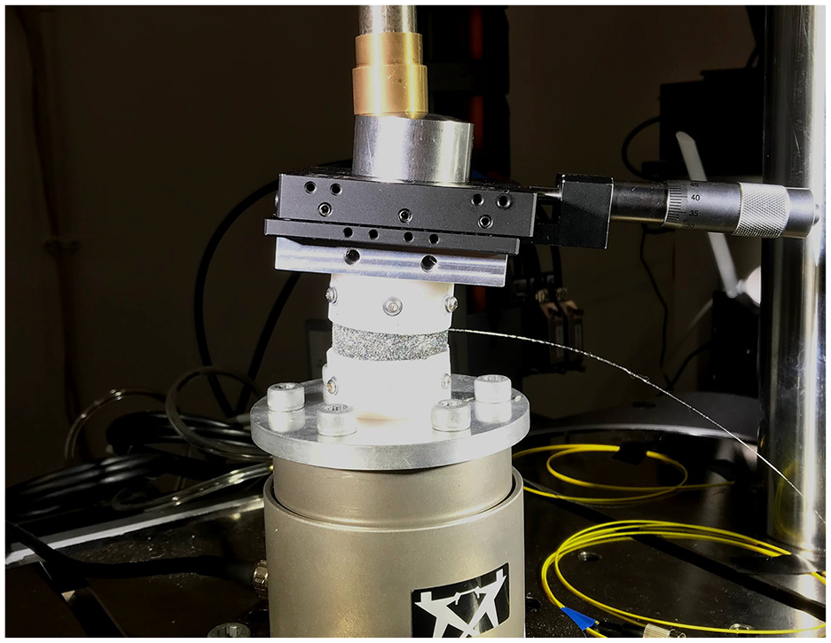
The test fixture demonstrating bending due to an offset introduced by the micrometer stage. Note the micrometer stage is held in position by the compressive load.
The test machine was operated in displacement control. Strain data was acquired at 0.1 mm axial displacement increments up to 1.2 mm final displacement, which is physiologically typical.39,40 The strain distribution was also measured at a range of bending angles under a constant axial displacement of 0.8 mm (≈300 N). Data was recorded at 0.5 ± 0.05 degree increments, verified with a digital clinometer. Axial and bending angle tests were conducted for the AF with and without an NP.
Results
The sensor reflected power-wavelength spectrum after embedding under no load is shown in Figure 7. The spectrum shows clearly distinguishable peaks, which relate to each of the gratings. The peak height can be seen to vary, which is a result of variability in the light source. This has no effect on the strain measurements, which are a result of peak shift in the wavelength domain and are not related to the peak height.
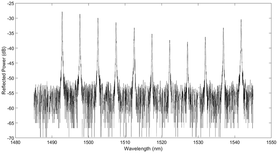
Sensor spectrum after embedding under no load.
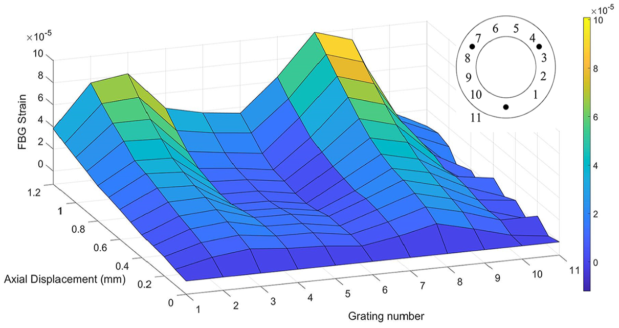
The strain distribution in the optical fibre in the nucleated implant subjected to uniaxial compression is shown in Figure 8. Henceforth, when the strain distribution in the AF is referred to, note that this is inferred from the optical fibre. This assumes the surrounding AF material experiences the same strains as the optical fibre itself. The reference grating (grating number 11) showed a flat strain-displacement response, indicating a high signal:noise ratio in strain measured at the other gratings. The sensor’s limit of strain resolution was characterised by a standard deviation of 10
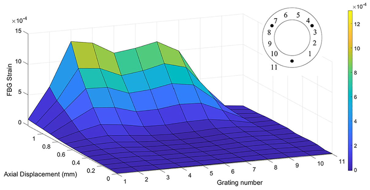
The strain distribution within the AF in uniaxial compression, with an NP. Two peaks can be observed, corresponding to fixation points. Grating numbers are shown in relation to the implant on the plan drawing (top right).
The strain distribution within the denucleated AF in uniaxial compression. Grating numbers are shown in relation to the implant on the plan drawing (top right).
An asymmetric load applied by translating the micrometer stage generated an uneven strain distribution in the nucleated AF (Figure 10). At a bending angle of 6 degrees, the peak compressive strain of 3.05
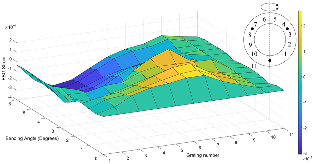
The strain distribution within the nucleated AF under varying bending angles. Positive strains are tensile and negative strains are compressive. Grating numbers are shown in relation to the implant on the plan drawing (top right).
The asymmetric strain distribution in the denucleated AF caused by the application of a bending load is shown in Figure 11. With a bending angle of 6 degrees, the highest compressive and tensile strains were 1.38
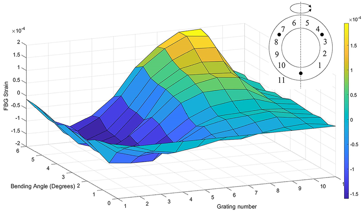
The strain distribution within the denucleated AF under varying bending angles. Positive strains are tensile and negative strains are compressive. Grating numbers are shown in relation to the implant on the plan drawing (top right).
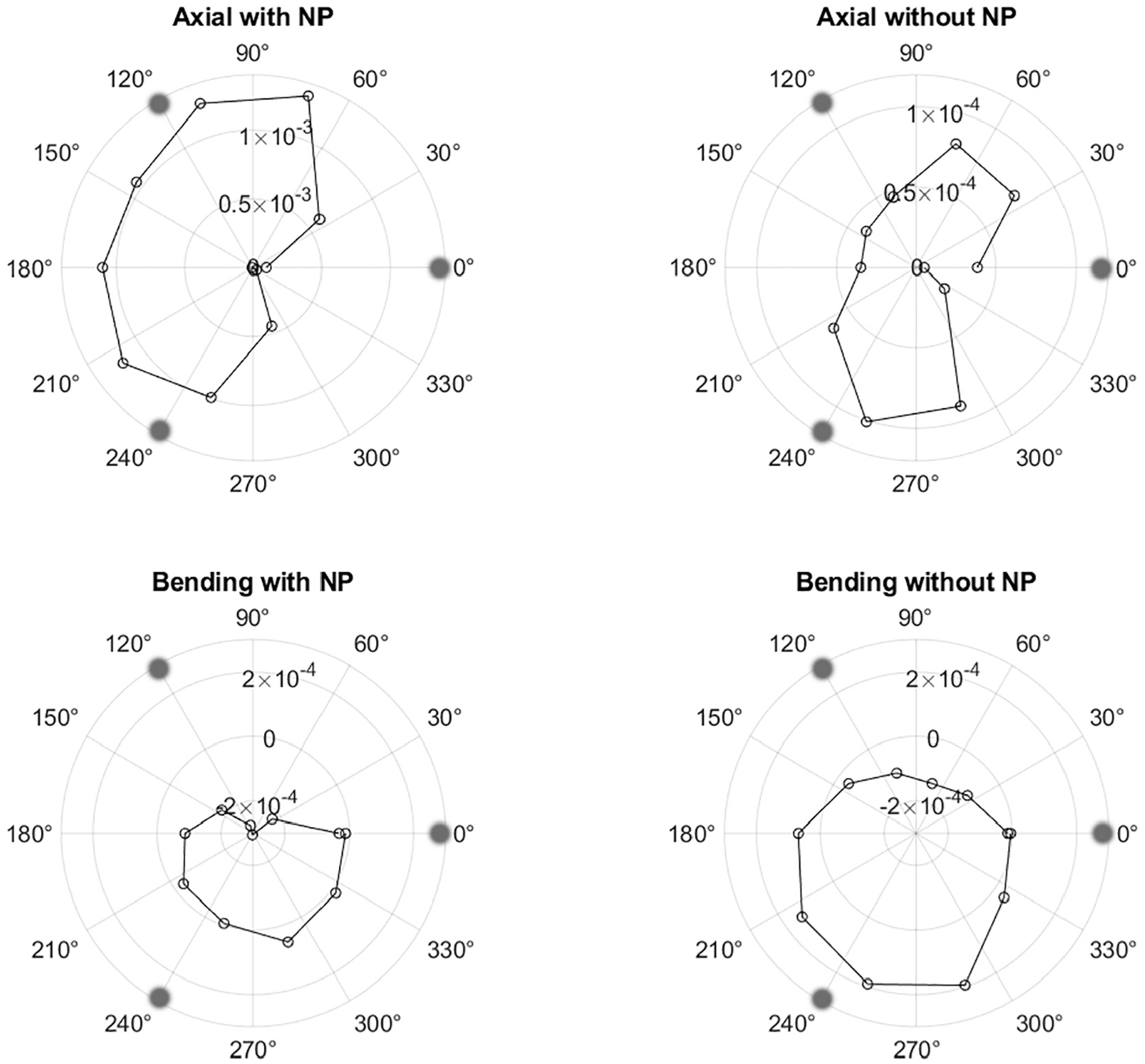
The strain measured with the fibre optic sensor, plotted in polar coordinates to correspond with the shape of the implant. The strain is plotted on the radial axis. The angular positions of the fixation pins are marked as grey dots. Note the zero-strain condition is located halfway between the centre and edge of the plot for the bending case due to the presence of compressive strains. The axes in each axial case are also different due to the larger strains in the nucleated case.
The bending angle can be correlated to FBGs 3 and 9 as these were located opposite each other and approximately at the most strained regions. Although there was no well-defined correlation between individual FBG strain,
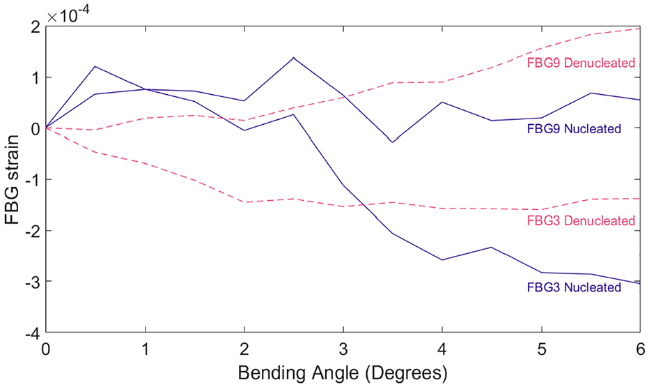
Strain in the nucleated and denucleated disc for gratings 3 and 9 at varying angles.
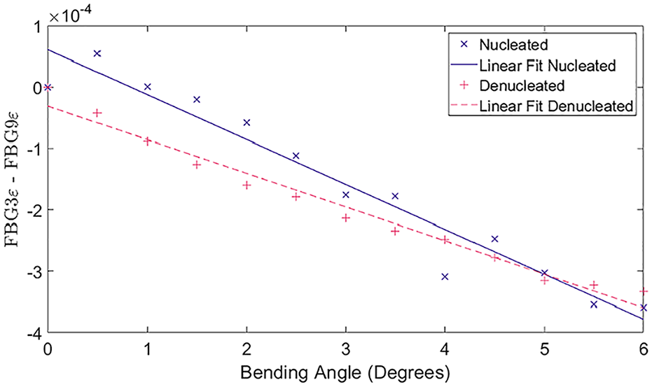
A scatter graph showing the linear relationships between the compression-tensile differential strain and bending angle.
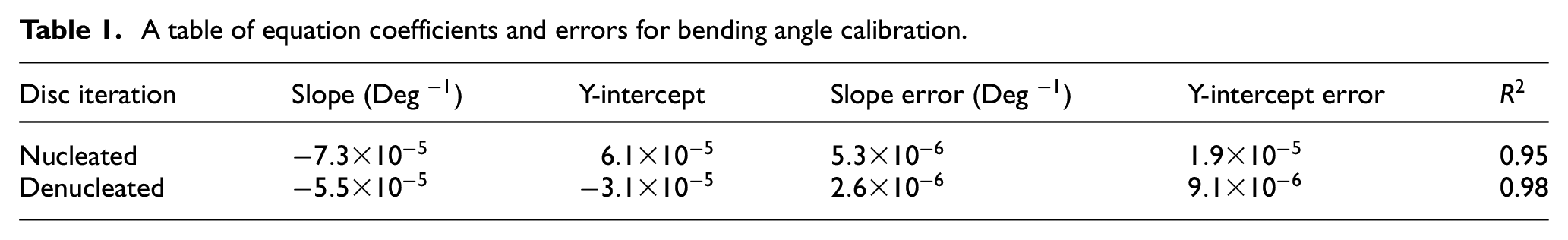
A table of equation coefficients and errors for bending angle calibration.
The strain distributions plotted on polar graphs at maximum axial/angular displacements for each case are shown in Figure 12. This visualisation corresponds to the shape of the implant. The fibre ingress and egress positions are centred around 0 degrees, hence the apparent zero strain at this point.
Discussion
There is a trend emerging for ADR designs to use compliant and biomimetic structures to more closely simulate the biomechanical behaviour of the natural intervertebral disc.41,42 These new ADRs operate very differently from traditional low-friction devices, so new characterisation techniques need to be established. While tribological assessment is suitable for current low-friction devices, compliant implants elastically deform instead of articulating so strain measurement has become relevant.
The measurement of internal strain in a compliant ADR is important for verifying that the device is deforming as intended. To this end, the aim of this study was to assess the feasibility of fibre-optic sensing in this application, specifically to monitor the circumferential strains within an artificial AF when subjected to physiological loads and displacements. Circumferential strain measurement has several uses in ADR development, such as monitoring the extent to which axial loads are converted to tensile stresses in an artificial AF (as seen in the natural disc) or measuring how fixation affects the strain distribution within the device.
In this study, the presence of the NP substantially increased the strain in the AF, which can be attributed to pressurisation of the NP. This is an important aspect of the natural disc, which aims to achieve an isostatic contact with the adjoining bone to help transfer stress through the spine without generating local stress concentrations on the relatively fragile vertebral endplates. 43
Another key feature of the fibre optic sensor is its ability to detect local strain concentrations within the implant. This enables an understanding of how certain design choices affect the strain distribution. In Figures 8 and 9, two peaks in the tensile strain were observed, corresponding to the location of the fixation pins. The increase in tensile strain was caused by local bending of the fibre optic sensor around the pins, confirmed by light leakage from a visual fault detector. This implies there was significant local deformation around the fixation pins, which was difficult to quantify using the FBGs, due to the fibre optic cable not being loaded in pure tension in these regions.
The strain values measured with the fibre optic sensor are lower than those measured in the natural disc by DVC, although it is challenging to quantify the significance of this due to the variability of testing protocols and natural tissue properties.44,45 Note that this discrepancy may also be related to the higher concentration of stiffer fibres relative to the natural disc. For reference, the tensile stiffness of natural AF specimens is around 5–50 MPa, as opposed to the circumferential stiffness of ≈100 GPa for the fibre-reinforced layer in the implant.46–48 For manufacturing simplicity, the Kevlar was wound circumferentially, as opposed to the oblique arrangement in the natural disc; however, circumferential fibre still allows pressurisation of the NP in axial compression, which is the loading regime of focus in this study. Although this aspect of the artificial model does not closely simulate the natural disc, it alone cannot be used to predict the global stiffness of the ADR model. An alternative corroboration is to look into trends and distributions, rather than absolute values. O’Connell et al. 45 subjected IVDs to bending and found similar behaviour to that measured with the fibre optic sensor: in flexion, the radial strain was tensile on the anterior side and compression on the posterior side, although the anterior aspect of the AF had a greater strain magnitude than the posterior aspect of the AF. They observed the reverse behaviour for extension. This is more akin to the denucleated implant, which also exhibited an asymmetrical radial or circumferential strain distribution. This could be explained by the partially degenerated state of the natural discs tested.
The main alternative to the fibre optic sensor is DVC, which requires a more complex experimental procedure but provides full-field strain, with a higher spatial resolution than the fibre optic sensor. Although not investigated in this work, the fibre optic sensor offers significantly improved temporal resolution compared with DVC, enabling dynamic strain measurement. There are methods to improve the performance of the fibre optic sensor, such as using shorter FBGs, multiple fibre optic cables or by exploiting birefringence. This technique has demonstrated that is it possible to decouple and measure three orthogonal strain components with embedded optical sensors. 49
In order to achieve accurate strain readings from an embedded fibre optic sensor, the material surrounding the fibre optic cable must be of similar stiffness to the fibre optic cable. Roriz et al. 34 found this difficulty when attempting to measure disc bulge with an FBG. To circumvent this issue, the fibre optic cable was embedded parallel to the Kevlar reinforcement. This approach will likely be viable with the majority of artificial fibre materials suitable for ADR construction since this group of materials generally have similar stiffnesses. For example, polyethylene fibres, which are often used in biomimetic ADRs, have a reported tensile modulus of 109–132 GPa.47,50–53 Kevlar lies in this range with a tensile modulus of 112 GPa. 48
In this study, the AF may be considered as a composite material. When factoring in the effect of the PDMS matrix, a circumferential stiffness of 97.8 GPa was estimated for the (1 mm thick) Kevlar-reinforced layer (equation (6)). Note that this calculation only provides an approximation due to several assumptions such as equal strain in the Kevlar and PDMS, the Kevlar and PDMS are bonded perfectly and the constituents have a constant elastic modulus. In this case, due to the large difference in moduli between the two constituents, the inaccuracies from these assumptions are accentuated relative to a more conventional composite material. Nevertheless, this approximated value is similar to the ≈70 GPa of a fibre optic cable 54 ; however, this does limit the potential for sensor placement in other areas of the implant. This may be alleviated through the use of a plastic fibre optic cable.

where,
Another limitation of fibre optic sensing involves bend losses and, if employed in a cervical implant, the fibre optic cable may be subjected to a bending radius as small as ≈5 mm. 56 In a standard single-mode fibre, this would induce bending losses of around 15 dB, 57 which would attenuate most of the measured signal. Depending on the quality of the gratings and interrogator, the response may not be measurable; however, this can be resolved with the use of bend-insensitive fibre.
The present study was conducted in vitro; however, optical fibres are easily fabricated to be biocompatible 58 and since there is precedence for electronically instrumented orthopaedic implants,59,39 optically instrumented devices warrant further investigation.
Conclusions
In this study, a fibre optic sensor was designed, fabricated and embedded into an artificial annulus fibrosus. With the use of fibre Bragg gratings and wavelength division multiplexing, the circumferential strain distribution was measured to a spatial resolution of 10 mm and a strain resolution of 10
Specific to the analogue used in this study, for a given displacement, the circumferential strain increased by approximately 10 times under axial loading when an artificial nucleus was added to the artificial annulus fibrosus. This demonstrated the transfer of axial load to circumferential stress, commonly reported for the natural disc. By measuring the asymmetry in strain when a bending moment was applied to the ADR, it was demonstrated that a bending angle could be measured to ±0.5 degrees.
Footnotes
Declaration of conflicting interests
The author(s) declared no potential conflicts of interest with respect to the research, authorship, and/or publication of this article.
Funding
The author(s) disclosed receipt of the following financial support for the research, authorship, and/or publication of this article: This work was supported by the EPSRC DTP 2018-19 (grant number EP/R513325/1).