
Abstract
The concept of full compensation against the resultant shaking forces and moments for arbitrary robots using a single active dynamic balancing mechanism is first addressed. And the application principle and general balancing conditions of the active dynamic balancing mechanism are presented. With the purpose of providing detailed description of these problems, a compact planar 3-degree-of-freedom active dynamic balancing mechanism is proposed. The active balancer is composed of three independent rotating bars with their respective actuators. The rotations of the three bars could change their center of gravity positions and then generate balancing forces for the unbalanced robots. Moreover, the changing of the angular acceleration of the bars can also generate a dynamic torque to balance the shaking moment. In order to present more detail of the balancing theory, the structure and kinematic and dynamic analysis of the proposed balancing mechanism are given. Finally, numerical examples illustrate the effectiveness of the proposed three-rotating-bar balancer.
Keywords
Introduction
Vibrations of a robot frame frequently occur when picking and placing payload or replacing various tools during operations, which result in shaking forces and shaking moments. As is well known, shaking forces and shaking moments are undesired since they cause fatigue, noise disturbances, and deterioration in accuracy. 1 Robots that can dynamically balance shaking forces and moments are expected to reduce wear, fatigue, noise, and cycle times and improve operating precision and control efficiency. 2 Therefore, dynamic balancing of the shaking forces and shaking moments is of great significance in the development of robotic technology.
A robot is dynamically balanced if, for any motions of the robot, all of the resultant inertia forces and resultant moments are equal to zero. 3 To make a robot dynamically balanced, an effective method is to eliminate the source of the vibrations by changing the configuration of the machine. According to what is determined by mechanic, two methods are applied eliminating the adverse impact of the vibrations: passive dynamic balancing (without computer control) and active dynamic balancing (with computer control). 4 Passive dynamic balance of a robot can be achieved by adjusting kinematic parameters such as the length or the mass of a link. 5 With the operation of passive dynamic balancing mechanism, side effects inevitably are produced. A considerable amount of additional masses and additional inertia arise from the application of counter masses (CMs) and the accompanying mass redistribution in passive dynamic balancing, increasing the input power, manufacturing cost, and structural complexity.6–10 Compared with passive dynamic balancing, the major advantage of active balancing with control system is that all of the shaking forces and shaking moments can be simultaneously vanished by a minimum number of additional elements. Moreover, with the superiority of adaptability, active balancing is possible to adjust balancing forces and balancing moments with changes of the mass and inertia parameters, which is available when mass and inertia change during picking and placing payload or replacing tools.
The concept of active dynamic balancing has been proposed in recent years.11–13 Since dynamic performances can be influenced by controlling parameters such as gains of the proportional–integral–derivative (PID) controller and the adaptive controller, researchers have adopted redundancy servo motor (RSM) to design path generator and improve dynamic performance for mechanisms including four-bar linkage and five-bar linkage. 5 Moreover, an approach of integrated design for dynamic balance concerning kinematic synthesis, dynamic performance, and input-speed trajectory is introduced to reduce the shaking force and moment.14,15 In order to decrease the complexity of the controlling algorithm, some researchers have proposed that adding additional balancing units can help realize the dynamic balancing. One single dynamic balancing unit was proposed for 6 degrees of freedom (6-DOF) balancing and the structure of a planar parallel mechanism with 2-DOF rotations being used to move the counter-rotary counter mass was implemented for the application of a planar robot. 16 A balancing theory of mass balancing of mechanisms using a single rigid body was addressed and the balancing method was illustrated. 17 An active disk with bevel gears and ball screw was designed for automatic active balancing of rotor-bearing systems. 18 A complex active dynamic balancer which consists of four independent controllable compensation inertias was implemented for a 2-DOF planar mechanism. 19
It is usual to use a disk to constitute an active dynamic balancing unit for active balancing of shaking moment in aforementioned methods.18,20 And the disk is always designed to be with large mass to generate enough moment, resulting in energy consumption. In order to reduce addition of mass and inertia, a compact and light-weighted three-rotating-bar balancer with minimum additional mass and inertia is designed as an active dynamic balancing mechanism (ADBM) in this study. With this structure, the rotation of three bars could render the change of the center of gravity position of the ADBM, which would generate 2-DOF balancing forces on the base of robot. In addition, the variation of the angular acceleration of the bars can also generate a torque to balance the shaking moment of the robot. In order to verify the performance of the three-rotating-bar balancer, the application principle, structural design, and kinematic and dynamic analysis are given in this study, and simulations of dynamic balancing with the mechanism are presented to illustrate the implementation and effectiveness of the ADBM.
General description of the dynamic balancing
As illustrated in Figure 1(a), the shaking forces and shaking moments generated by the individual moving elements in a robot (including serial robot and parallel robot) are represented by black arrows. The summation of all these shaking forces and moments results in net shaking forces and moments which exert to the base of the robot, as indicated by the green arrows. Based on the spatial structure of the robot, there are at most three independent net shaking forces (along x-, y-, and z-axes) and at most three independent net shaking moments (about the x-, y-, and z-axes). Assuming that there are n individual elements exerting shaking forces and shaking moments at the base of the robot, let

where mi and Ii are the mass and the moment of inertia of the ith shaking element,

(a) Shaking forces and shaking moments caused by individual moving elements and (b) balancing forces and balancing moments compensated by the balancing unit.
Because of the influence of the machine vibrations, the state of the base of the robot is no longer to be stationary but to move with the shaking force and the shaking moment. In order to eliminate the machine vibrations, the balancing mechanism should produce three balancing forces and three balancing moments that are equal and opposite to the net shaking forces and net shaking moments.
For the purpose of generating balancing forces and balancing moments in each of the directions, three independent actively driven counter-rotating elements and three independent actively driven CMs are applied, which are illustrated as rotating disks and rectilinear sliders in Figure 1(b). The generalized balancing forces are represented by red arrows.
Design and kinematics of the ADBM
Actually, the 6 DOFs shown in Figure 1 are not balanced, respectively, by independent balancing elements in engineering practices. In order to make the balancing mechanism more compact, the most common method is combining (some of) the balancing elements. An ultimate case is to balance all of the 6 DOFs with one single spatial spherical balancing element, as proposed by Van der Wijk and Herder. 1 The only disadvantage of the design is that actuators of the sphere are not easily mounted and the 6 DOFs of the sphere are practically impossible to be simultaneously controlled.
This study presents the concept of a 3-DOF balancer which combines two CMs and one counter inertia (CI) for simultaneously force balancing and moment balancing of a planar x-y robot. To make the planar x-y robot to be dynamically balanced, two independent shaking forces and the vertical shaking moment should be balanced. Therefore, the balancing unit must be designed to be of 3-DOF.
CM and CI are the most common application of the basic mechanical design for balancing planar robots. The movements of two CMs are designed to be rectilinear and mutually perpendicular to generate two balancing forces in two directions. Since the motion of the CM should be of rectilinear guidance, and the two CMs are actuated to move on the tracks on the platform, the area occupation of the ADBM is demanded. As for the CI, a rotating disk is adopted about z-axis to balance the shaking moments. The high inertia always leads to high mass or large size, which results in high mass addition or large space demand of the ADBM. Obviously, it goes against the objective of reducing energy consumption and increasing ergonomics. In order to enhance the performance and simplify the structure of the ADBM, a compact three-rotating-bar planar linkage is presented for active dynamic balancing of a planar robot.
The ADBM is composed of three independent rotating links, and its schematic is given in Figure 2. In order to eliminate the shaking forces and shaking moments of the planar robot, the ADBM is mounted on the base of the robot. The rotation of the links of the ADBM could exert forces on the base of the unbalanced robot for offsetting the shaking forces and making the robot dynamically balanced. Moreover, with the change of the rotation acceleration of the links, the angular momentum of the ADBM is no longer constant; it is thus able to generate a torque to offset the shaking moment of the robot.

Three-rotating-bar linkage of the ADBM.
As illustrated in Figure 2, all links of the ADBM are structurally similar but different in masses, lengths, and positions. mi, li, and θi represent the individual mass, position of the center of mass, and initial rotation angle of the ith link, respectively. The inertial frame Q of the base of the robot is first established and then the position of the fixed protection of the ith rotating joint with respect to Q is noted

The rotations of the links which lead to the changes of the linear momentum and angular momentum of the ADBM could contribute external force and external torque exerting to the base of the robot. The resultant inertia force


where
According to equations (4) and (5), the balancing forces and balancing moments are influenced by the center of gravity positions of the links. And the center of gravity positions are determined by the locations of the links and then the forces and the moments are relative to the rotation variables. Substituting the expression of vector


Here,


Therefore, equations (6) and (7) can be combined and written in matrices form

The matrices
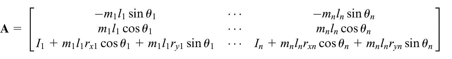

The parameters of mi, ri, and li are constants and can be obtained through the constructive design of mechanism.
According to equation (10), the dynamic force
Dynamics analysis
The mechanism assumed to be influenced by the shaking forces and shaking moments which needs to be dynamically balanced is an x-y planar robot. The three-bar ADBM is mounted on the base of the robot to make the mechanism dynamically balanced, as illustrated in Figure 3. The inertial frame O is first established and then a coordinate frame Q is attached to the center of the robot base. fsx, fsy, and τs, respectively, denote two independent resultant shaking forces and one resultant shaking moment applied to the planar robot.

Schematic of the ADBM for dynamic balancing of the planar robot.
The base of the robot is subjected to the resultant inertial force


where
According to equation (10), the inverse kinematics can be expressed as
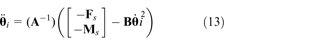
The desired rotational accelerations of the links of the ADBM can therefore be calculated according to equation (13). Then, appropriate parameters of the actuators used to move the links can be configured, and the rotations of links of the ADBM can exert balancing forces and balancing moments on the unbalanced robot to make the robot dynamically balanced.
Determination of resultant shaking forces and shaking moments
To get the inertia forces and torques of the platform, the net shaking forces and moments exert to the base of the robot must be obtained first. There are a lot of methods to get the vibrational signals.21–23 One effective technology is to acquire the linear and angular accelerations of the shaking elements.
They can be obtained through mounting two accelerometers on the rotating element to be detected. For each accelerometer, its acceleration can be expressed as follows


where

where
Determination of the rotational variables
and θi
Rotational variables of each bar can be determined using an integration technique. First, the rotational velocity

And the rotation angle

where k is the time step and Ts is the sampling period.
Singularity analysis of matrix A
According to equation (10), when the number of the links is supposed to be three, both matrix
In order to obtain solutions of equation (13), matrix

In order to ensure the three-bar linkage is available as an ADBM, the matrix

Assuming that the three bars of the balancing mechanism are homogeneous, the moment of inertia of the ith bar can be expressed as

Substituting equations (19) and (21) into equation (20), we obtain

Numerical examples
In order to verify the ADBM proposed in this study, simulations by MAPLE™ were performed. When the shaking forces and shaking moments are acquired by the accelerometers mounted on the robot to be balanced, the desired balancing forces and torque generated by the ADBM can be determined. Then, the rotational accelerations of the bars of the ADBM can be calculated through inverse kinematics. The actuators will then actuate the ADBM according to the calculated values and produce forces and moments that react on the unbalanced robot. By comparing the inertia forces and torques of the base of the robot with ADBM and without the ADBM, the effectiveness of the ADBM can be thus verified.
As illustrated in preceding sections, three motors and actuators are included respectively to drive the three independent bars. Therefore, the ADBM is composed of three independent rotating bars and their corresponding actuators. The position and the way in which the actuator is mounted have influence on the balancing performance. For example, motors used for driving the bars can be mounted on the end of the links. Compared with mounting them on the base of the mechanism, their mass is advantageously used as a balancing mass which improves the effective balancing moment of inertia too. On account of motors being mounted on the end of the rotary bar, the three rotary bars of the ADBM should be designed different in lengths, such that rotating motors are unable to collide. The parameters of the bars of the ADBM are shown in Table 1. Moreover, in consideration of the essential conditions of the nonsingular
Parameter configuration of the ADBM.

To illustrate the effectiveness of the ADBM, the robot is supposed to be subjected to the external shaking forces (along x- and y-axes) and shaking moments (about the z-axis). Since the stochastic periodic motions of the shaking elements can be decomposed into a series of trigonometric functions using Fourier transformation, 2 the shaking forces and shaking moments that arise from shaking elements are formulated using sinusoidal functions, as shown in Table 2. Regular shaking conditions are given in Case A, and extra disturbance terms are involved in Case B for purpose of testing the anti-interference performance and reliability of the ADBM, as well as demonstrating the adaptability of the active control, which allows dynamic balancing of variable payload.
Two cases of resultant shaking forces and moments of the robot.

The ADBM is assumed to be mounted on the base of the unbalanced robot which is subjected to the shaking forces and moments. In order to counteract the shaking influence, the bars of the ADBM should rotate along a planned trajectory to generate a balancing effect.
According to the given conditions of Case A, the calculation of the desired dynamic trajectory of each bar of ADBM can be accomplished by MAPLE™. The curves of the desired rotational accelerations, rotational speeds, and rotation angles of three bars are, respectively, shown in Figures 4–6.
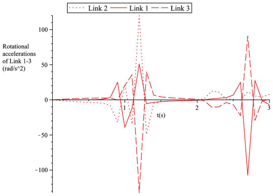
The desired rotational accelerations of Link 1–3 of the ADBM under Case A.

The desired rotational speeds of Link 1–3 of the ADBM under Case A.

The desired rotation angles of Link 1–3 of the ADBM under Case A.
In order to demonstrate the applicability of the ADBM, it is easy to calculate the actual balancing forces and balancing moments applied by the ADBM. With the obtained motion parameters of the bars of the ADBM, the actual forces (along x- and y-axes) and shaking moments (about the z-axis) applied by the ADBM on the robot can be computed. Then, the results are shown to compare with the shaking forces and shaking moments in Figures 7 and 8.

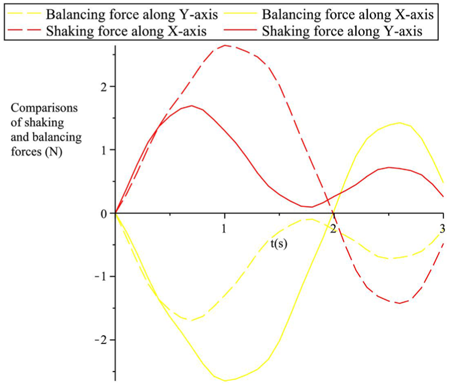
The balancing forces and shaking forces applied to the robot under case A.
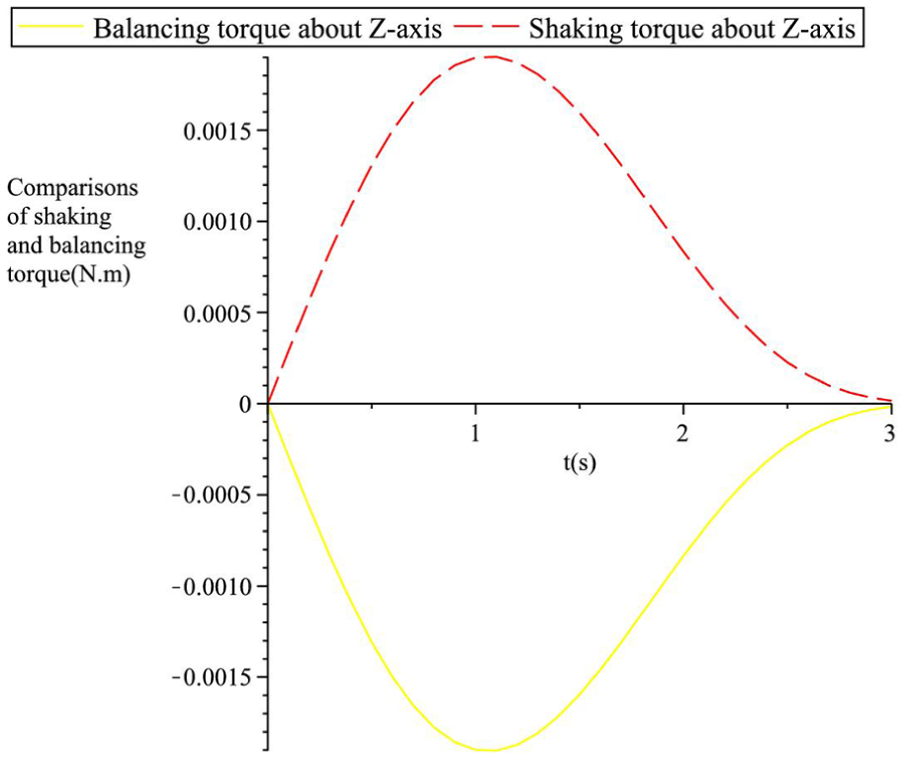
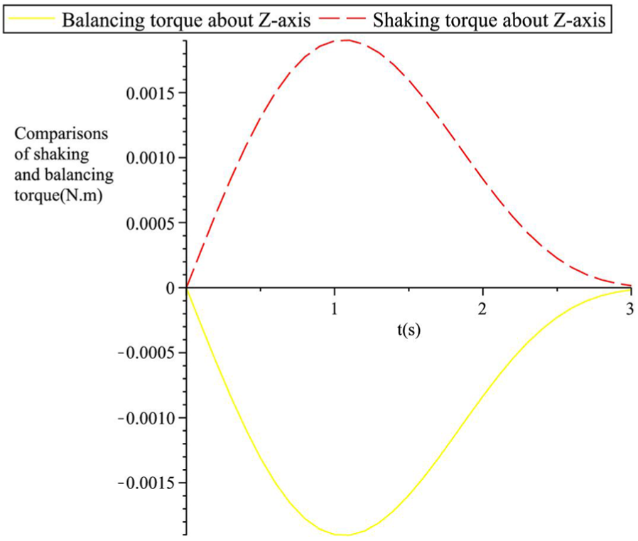
The balancing torque and shaking torque applied to the robot under case A.
Additionally, to test the anti-interference performance and reliability of the ADBM, extra disturbance terms are involved into the overall shaking forces and shaking moments of the robot in Case B. Similarly, the desired kinematic parameters of the bars of the ADBM under these circumstances also can be calculated. The results of desired rotational accelerations, rotational speeds, and rotation angles under Case B are, respectively, shown in Figures 9–11.

The desired rotational accelerations of Link 1–3 of the ADBM under Case B.

The desired rotational speeds of Link 1–3 of the ADBM under Case B.

The desired rotation angles of Link 1–3 of the ADBM under Case B.
Next, the effectiveness and robustness of the ADBM are reconfirmed by comparing the generalized balancing forces with the shaking forces given in Case B. After obtaining the numerical solutions of the ADBM in given conditions of Case B, the summation forces and moments that the ADBM and shaking elements exert to the base of the robot are, respectively, shown in Figures 12 and 13.
The balancing forces and shaking forces applied to the robot under case B.
The balancing torque and shaking torque applied to the robot under case B.
Figures 7, 8, 12, and 13 present the balancing forces and torques applied to the base of the robot in the three orthometric directions when giving variable shaking forces and torques. Inspecting Figures 7 and 8, the balancing forces and moments generated by the rotation of three bars of ADBM are equal and opposite to the prescribed shaking forces and shaking moments, which means the summation of reaction forces and torques at the base of the robot is zero. It proves that the robot turns to be dynamically balanced with the three-rotating-bar active balancing mechanism. Therefore, the effectiveness of the ADBM is primarily certified.
As for Case B, the shaking forces and shaking moments that exert on the robot are different from that in Case A. According to Figures 12 and 13, the resultant forces and moments of the robot and the ADBM are also equal to zero. That means the base of the robot could also be dynamically balanced with the effect of the ADBM even when the robot suffers stochastic disturbances. The dynamic balancing with respect to different vibrations is therefore verified. The results demonstrate that dynamic balancing still can be achieved in spite of variations in the shaking elements. As a summary, the three-rotating-bar planar ADBM proposed in this study is able to realize the dynamic balancing of the platform and it can resist certain disturbances as well.
Conclusion and future research
For purpose of reducing or even eliminating the wear, fatigue, noise induced by vibrations, or brisk movements of machines and robots, it is preferable to make the mechanism shaking force and shaking moment balanced. Taking the demands of a low addition of mass and inertia into consideration, an ADBM with computer controlled is adopted to achieve the requirements in this study.
A novel and compact three-rotating-bar planar linkage is presented in this study as a balancing mechanism for active dynamic balancing of a planar robot. Numerical examples illustrated the effectiveness of the ADBM and the enhanced dynamic performance of the system.
Future research will focus on building a prototype of the mechanism for the purpose of demonstrating the implementation and effectiveness of active dynamic balancing in practice. Dynamic balancing of picking and placing variable payload on the robot will be illustrated. Moreover, structural design of a spatial 6-DOF ADBM is attempted to be realized.
Footnotes
Acknowledgements
The authors would like to thank Clement Gosslin for his guidance and help.
Academic Editor: Long Cheng
Declaration of conflicting interests
The author(s) declared no potential conflicts of interest with respect to the research, authorship, and/or publication of this article.
Funding
The author(s) disclosed receipt of the following financial support for the research, authorship, and/or publication of this article: The authors would like to acknowledge the financial support of the National Natural Science Foundation of China (Grant Nos 51505190 and 51575236). This work was also supported by Jiangsu Province Natural Science Foundation (Grant No. BK20150153), the open project of Jiangsu Key Laboratory of Advanced Food Manufacturing Equipment and Technology (Grant No. FM-201405 and FM-201501), and fundamental research funds for the central universities (Grant No. JUSRP51511).