
Abstract
This article presents vibration control performances of a semi-active railway vehicle suspension system using a magneto-rheological damper tested on the roller rig. In order to evaluate control performances, a mathematical railway vehicle model with 15 degrees of freedom is first derived to represent the lateral, yaw and roll motions of the car body, bogie frame, and wheel set, respectively. Based on the formulated model, the design parameters of magneto-rheological damper are determined to undertake a compatible comparison with dynamic performances of conventional (existing) passive railway vehicle suspension system. The designed magneto-rheological damper is manufactured and its field-dependent damping force characteristics are experimentally evaluated. Subsequently, in order to enhance the ride quality of a railway vehicle suspension equipped with magneto-rheological damper, a skyhook controller associated with an extended Kalman filter is designed in a state space representation. The railway suspension system incorporated with the car body and two bogies is then experimentally set up on the roller rig in order to evaluate the ride quality. It is demonstrated from experimental realization of the controller that the ride quality of the suspension system with magneto-rheological damper can be significantly enhanced compared with the existing passive suspension system.
Keywords
Introduction
To meet the needs of modern society, advanced mass transportation systems have been and being built throughout the world. Demand has brought about the development of high-speed railway vehicles, which are proficient and cost-effective type of transportation. 1 However, the high velocity of railway vehicles may cause significant car body vibration, which can reduce ride quality and also affect adverse ride stability.2,3 Thus, the development of more advanced railway vehicle suspension system is needed to effectively reduce unwanted vibrations and hence increase both the ride comfort and the stability. Railway vehicle suspensions can be classified as primary and secondary suspensions.4–6 The primary suspension consists of four separate non-linear axle-box dampers per bogie and is located between the wheel sets and the bogie frame. The secondary suspension is located between the bogie and the car body. They are used to bear the car body and allow the bogie to rotate when the railway vehicle negotiates the bends. Since car body vibration is directly related to the secondary suspension, numerous researches related to the secondary suspension have been performed to improve the ride quality and stability.
A passive secondary suspension composed of a spring and hydraulic damper has been widely used due to its several advantages such as compactness, cost-effectiveness, and easy maintenance. 7 However, the passive type of the hydraulic damper cannot simultaneously meet ride quality and ride stability requirements in high-speed operation. Since the high-speed train has lateral vibration modes due to aerodynamic force, high damping force is required to guarantee the ride stability. It is here noted that the high damping force can negatively affect the ride quality. Thus, using the constant dynamic stiffness of the passive suspension is not suitable for the enhancement of the ride quality and stability. In contrast, an active suspension can generally guarantee reasonable performances in various running conditions.8,9 However, active suspension requires large power sources and complex control algorithms with a high cost. Moreover, active suspension system may cause the instability due to the fault of sensors and/or actuators. Accordingly, recently, several research works on the semi-active suspension system for the railway vehicle have been undertaken to overcome these problems. By controlling the damping of the system, the semi-active suspension system can improve isolation performance without large power sources and this excellent performance can be achieved using simple control algorithms such as the skyhook controller.
In particular, tunable semi-active suspension systems featuring magneto-rheological (MR) fluids have been proposed to obtain excellent isolation performance and successfully been realized for many suspension systems of passenger vehicles.10,11 It is well known that one of the salient properties of MR fluids is the controllability of the yield stress which can be adaptively tuned by the intensity of applied magnetic fields.12–14 This can provide several benefits to many different devices or systems utilizing MR fluids. The semi-active suspension system with MR damper has several benefits such as high stability, smooth motion, and field-dependent vibration control performance. Sun et al. 15 did experimental work by applying MR dampers to railway vehicles. Lau and Liao 16 tested suspension performance of a unit component by incorporating MR dampers with railway vehicle suspension system. Through numerical simulation of a railway vehicle model, they evaluated suspension performance of an on–off control technique and found that car body vibration could be reduced to the maximum of 38.9%. Liao and Wang17,18 proposed 9-degrees-of-freedom (DOF) railway vehicle system and evaluated the effectiveness of the dynamic model via numerical analysis. It has been shown that the performance is very good to control the railway system along the vertical direction. Ha et al. 19 investigated the ride quality of a railway vehicle system integrating with a semi-active suspension system equipped with MR damper. They used a ride index method to evaluate suspension performance and quantify the ride quality. Using numerical simulation, they also showed that the ride quality could be significantly enhanced by controlling the field-dependent damping force of MR damper. From the literature survey, it has been found that many research works on the semi-active suspension with MR damper have been undertaken under real road conditions or using hardware in the loop simulation (HILS) method for passenger cars.
However, the research work on the semi-active suspension system with MR damper for railway vehicles under real environment conditions is considerably rare. Most research works done so far have been limited to numerical simulation and small-scale railway vehicle experiments. Therefore, an experimental work based on real field conditions under real-scale railway vehicle is needed to validate practical feasibility of the semi-active suspension system with MR dampers. Consequently, the main technical contributions of this research work can be summarized as follows:
Design and manufacturing of a real-scale MR damper based on the mathematical model of the railway vehicle semi-active suspension system;
Experimental implementation of the skyhook controller associated with extended Kalman filter under real-scale roller rig considering car body of the railway vehicle;
Comparison of the ride comfort between the proposed semi-active and conventional passive suspension systems based on UIC 513 R standard. 20
This work first formulates a mathematical railway vehicle model with 15 DOFs to determine the principal design parameters of MR damper. Based on actuating force model due to the field-dependent yield stress of MR fluid, the design parameter of MR damper is determined via computer simulation to satisfy the required actuating force. The valve type of MR damper is then manufactured and its field-dependent damping force characteristics are experimentally evaluated. Subsequently, a simple, but very effective skyhook control algorithm is developed considering extended Kalman filter. After establishing experimental setup, which consists of real-scale roller rig with motor, MR damper, car body, and large-sized shaker, the proposed control algorithm is experimentally realized and effective values (acceleration) of the ride comfort are presented in frequency domain. It is shown that the ride quality of the railway vehicle can be significantly enhanced by applying the proposed semi-active suspension system incorporating with MR damper.
Dynamic model of railway vehicle suspension
A train is composed of several locomotives, passenger cars, and freight cars. Each railway vehicle consists of a car body, two bogies, four wheel sets, and suspensions between the three components, as shown in Figure 1. Table 1 shows the DOF of the mathematical model. The proposed MR damper is installed between the bogie frame and the car body. To derive the governing equation of the railway vehicle, the car body, bogies, and wheel sets are assumed to be rigid components. All suspensions are represented by springs and dashpots. The wheel sets are assumed to follow the track perfectly along the vertical direction, and the roll motion of the bogie frame is neglected. Additionally, the wheel set motion is initiated by creep force input between the wheel and the rail. With these assumptions, the car body has 3 DOFs, and the two bogie frame and four wheel sets each have 2 DOFs. Accordingly, the total 15-DOF railway vehicle model for a four-axle two-bogie vehicle can be expressed as follows
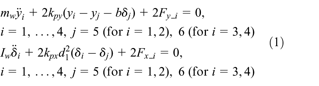


where, mw, mb, and mc are the masses of the wheel set, bogie frame, and car body, respectively. Iw, Ib, and Icy are the moments of inertia about the z-axis of the wheel set, bogie frame, and car body, respectively; Icr is the moment of inertia about the x-axis of the car body; kpy and kpx are the spring constants of the primary suspension between the bogie frame and the wheel sets along the y- and x-axes; ksy and csy are the spring constant and damping coefficient of the MR damper; FMR is the controllable force of the MR damper; Fx and Fy are the creep force along the x- and y-axes; b and d are the distance between the wheel set and the bogie frame; and l and h3 are the distance between the car body and the bogie frame, respectively.

15-DOF mathematical model for railway vehicle system: (a) front view and (b) top view of bogie frame.
Variables and model degrees of freedom.

Design and manufacturing of MR damper
MR fluid consists of magnetizable particles in a carrier fluid. It is generally known that the rheology of MR fluid is instantaneously and reversibly changed by applying a magnetic field. Without the magnetic field, MR fluid behaves like a free-flowing liquid, but when the field is applied, the particles align with the field. This phenomenon is due to the polarization induced in the particles by the field. The induced dipoles make the particles form columnar structures parallel to the field. This phenomenon can solidify the fluid and hence restrict flow motion. With the additional restriction, mechanical energy is required for the chain structures to yield. In this work, the Bingham model is used to define the rheological behaviors of the MR fluid

where τ is the total shear stress of the MR fluid, η is the viscosity constant, and

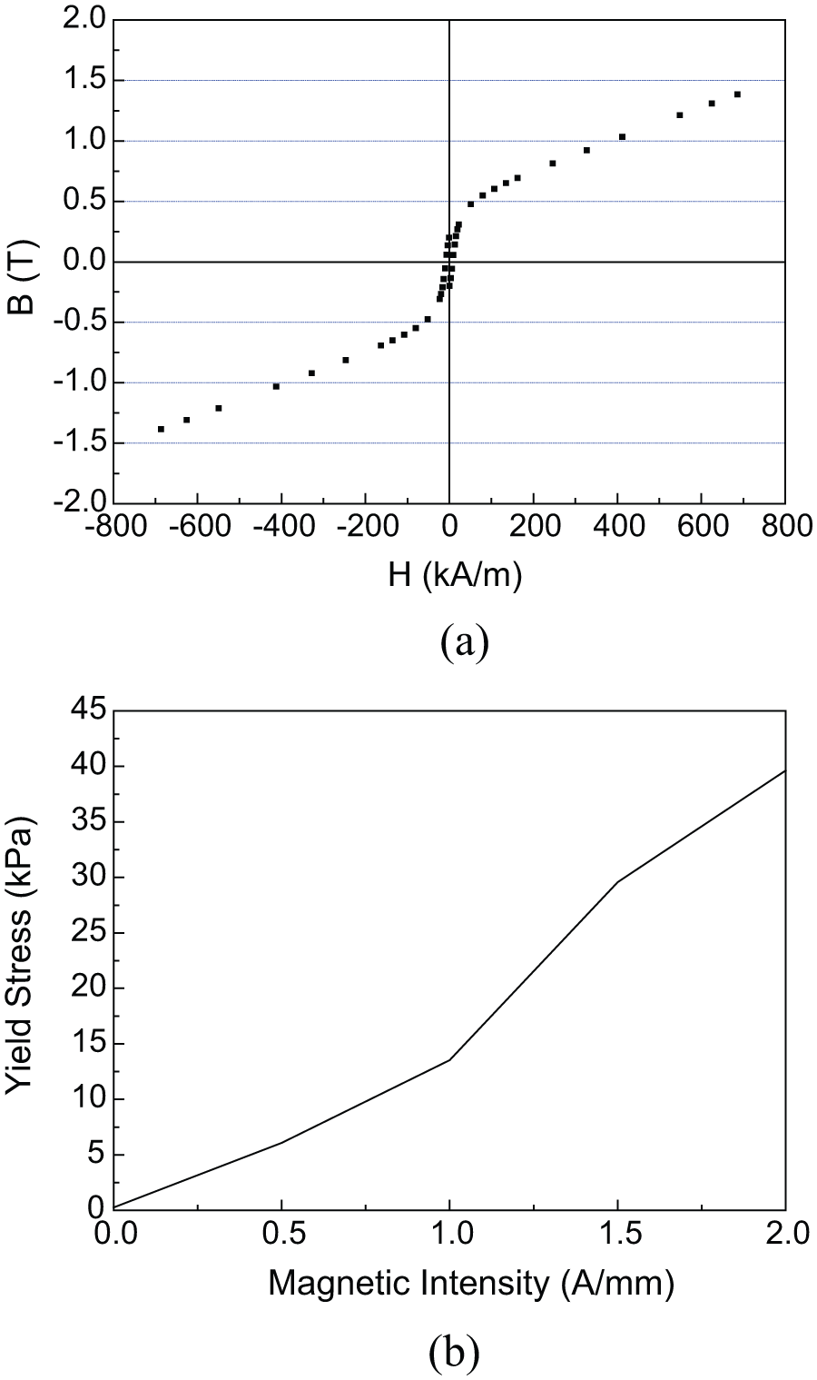
Magnetic field-dependent properties of MR fluid: (a) H-B curve of MR fluid and (b) H-yield stress curve of MR fluid.
A valve-type semi-active damper is proposed based on the rheological features of MR fluid, as shown in Figure 3. Figure 3(a) shows the schematic configuration of a railway damper featuring MR fluid. The damper consists of an outer cylinder, inner piston, piston head, floating piston, and gas chamber. The MR damper is separated into upper and lower chambers by the piston head. The role of the gas chamber and floating piston is to compensate for the volume change caused by the piston movements. The MR fluid flows in the gap between the coil and the outer housing of the piston head. During operation, MR damper generates a damping force that is mainly induced by the fluid friction of the MR fluid. The fluid friction is determined by the geometric shape of MR damper, the velocity, and shear stress of the MR fluid. The shear stress can be controlled by the magnitude of the magnetic field, which is tuned by the current applied to the coil.

Manufactured full-scale MR damper: (a) schematic configuration and (b) photograph.
The damping force of the MR damper consists of four elements: viscous friction force, controllable force, spring force induced by the gas chamber, and mechanical friction force. In the modeling process, the mechanical friction force is assumed to be zero. To derive the damping force model, the following are assumed: incompressible MR fluid, steady-state behavior of the fluid, and laminar flow with movements on the stream line. The heat loss is also assumed to be negligible. Based on these assumptions, the damping force can be expressed as follows

where P1, P2, and Pa are the pressures of the upper chamber, lower chamber, and gas chamber, respectively; Ap and As are the area of the piston and piston shaft; P0 and V0 are the initial pressure and volume of the gas chamber, respectively; γ is the coefficient of thermal expansion; and xp is the piston velocity.
To derive the pressure drop

where Qd is the flow rate of the MR fluid; µ is its post-yield viscosity; Ld, Rd, and d are the length, average radius, and gap of the annular duct, respectively; and c is a coefficient that depends on the flow velocity profile. Summarizing the relation between equations (5) and (6), the damping force can be rewritten as follows

The first term means the spring force of the gas chamber, while the second and third terms represent the viscous friction force and controllable force of the MR fluid, respectively.
As mentioned before, high damping force is required to guarantee the stability of a high-speed railway vehicle. Based on the governing equations of a railway vehicle (equations (1)–(3)), the required damping force is calculated according to the piston velocity of the damper, as shown in Figure 4. The maximum damping force is 10 kN and the maximum damping rate is 60 kN s/m. The design parameters of the MR damper are chosen to generate these required damping force characteristics according to equations (4)–(7). It is also remarked that the suspension performance without control input to MR damper is same as that of existing conventional passive damper. The radius of the MR valve (Rd) is 28 mm, the length of the magnetic pole (Lp) is 34 mm, and the gap between the magnetic poles (td) is 1 mm. The calculated damping force of MR damper is also shown in Figure 4. The figure shows that the generated damping force of MR damper is tuned by the magnitude of the magnetic fields. After manufacturing MR damper, the damping performance was tested. Figure 5(a) presents the measured damping force with respect to the piston velocity with various magnetic fields. This was obtained by calculating the maximum damping force at each velocity. It is clear that the damping force increases as the magnetic field increases. For example, the damping force of 586 N at a piston velocity of 0.3 m/s is increased to 14.23 kN by applying an input current of 0.8 A. Figure 5(b) presents the damping force of the MR damper as a function of the piston velocity at a medium frequency of 3 Hz and amplitude of 15 mm. It is noted that the manufactured MR damper can generate the required damping force by tuning the magnetic input.

Calculated damping force for determination of design parameters of MR damper.

Measured damping force characteristics of MR damper: (a) damping force versus velocity and (b) displacement versus damping force.
Formulation of control algorithm
To evaluate the control performance of the semi-active railway suspension system with MR damper, a skyhook controller is used. As well known, the skyhook controller is a semi-active controller and non-model-based controller. The control logic is relatively simple, but its effectiveness is high for many control systems. Since the railway vehicle system consists of many components, the dynamic model of railway vehicle system may have substantial error source in model. Accordingly, a simple, but very effective skyhook controller which does not require accurate dynamic model is very frequently used in railway vehicle system.21–23 The control input of the skyhook controller is given by

where Csky is the control gain and Vcar is the velocity of the car body. Since the control input should be determined according to the motion of the piston movement, the following actuating condition for the semi-active controller is required

where Vcar*bogie is the relative velocity of the car body and bogie.
On the other hand, to obtain the velocity of the car body and bogie, an accelerometer, a linear variable differential transformer (LVDT), and extended Kalman filter are used. Due to the difficulty of integration to obtain estimates of the velocity, the measured relative displacement between the car body and the bogie is also used. 24 Two accelerometers are attached at end points of MR damper, and the LVDT is installed between the top and bottom of MR damper. Accordingly, the measurement process can be modeled as follows
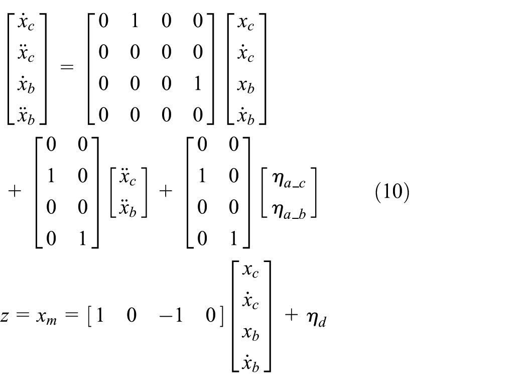
where

where

Accordingly, the extended Kalman filter for this system runs using the following rules
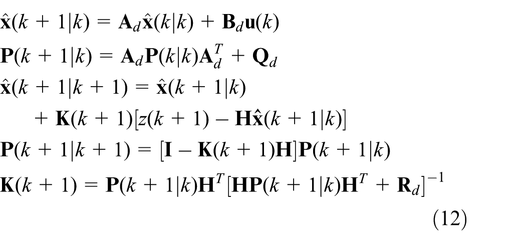
where

Simulation results of railway vehicle using MR damper with skyhook controller.
Control experiment using roller rig
An experiment is performed on the roller rig by replicating the real field test with the same running conditions to validate practical feasibility of the proposed semi-active suspension system for the railway vehicle. The roller rig is a structure that supports equipment being tested by loading the wheels of the rolling stock on a roller, which represents the rail. Figure 7 shows the roller rig which is used for performance evaluations. To rotate the wheel axle and excite the railway vehicle, a motor and exciter are installed on the front wheel axle set. As shown in Figure 7, the rear wheel axle set is fixed, and vibrations along the lateral and vertical directions are transmitted by the exciter. The conditions of the railway vehicle running at a speed of 150 km/h are realized by the motor and the exciter. To measure the acceleration and displacement, an accelerometer (model 13201A; Measurement Specialties™) and a LVDT (model P101, Positek) are installed on the car body. These sensors are connected with a dSPACE DSP board DS1104, which has high-speed A/D and D/A converters. Figure 8 shows the control block diagram for the railway vehicle suspension system with MR damper. In order to calculate the damping force and measure the signals, dSPACE DSP Board DS1104 is utilized. And current amplifier is used to generate the current input. The desired damping force is calculated for the skyhook controller. And then, the input current to MR damper is calculated according to the relationship between current and damping force shown in Figure 5. However, in order to simplify the control procedure, the combined control gain related to force and current is used in this work. The control gain of the skyhook controller is chosen to be 1.6 according to trial and error method. Figure 9 shows the signal processing results of the extended Kalman filter for the measured signal. The velocity information is properly estimated from the results. It is known that tuning the covariance values of extended Kalman filter is so difficult because the tuning process is often repetitive and the model has some of the error sources. One alternative method is to assume that these error sources do not exist and set the covariance values equal to their factory default covariance values which are supplied from sensor manufacturing company. Here, covariance values for qc, qb, and r are determined to be 1 × 10⁻⁵ m/s2, 5 × 10⁻¹¹ m/s2, and 3 × 10⁻⁸, respectively. These values have been offered from Sensor Company and verified via experiments. Then, control inputs are properly calculated with the extended Kalman filter and the input current determined from the skyhook controller is applied to the MR damper via the current amplifier.

Experimental apparatus for real-scale roller rig test: (a) schematic configuration and (b) photograph.

Block diagram for controller implementation on the roller rig test.

Dynamic responses: (a) measured signals and (b) estimated signals from extended Kalman filter.
Results and discussions
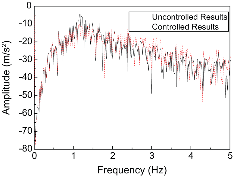
In order to evaluate the control performance and ride quality of the railway vehicle system, an additional accelerometer is attached to the car body. During the experiment, the control performance has been compared with the results without control input. Figures 10 and 11 show the measured results of the car body in the frequency domain and applied actual damping force based on the control input. It is clearly seen that the vibration magnitude at 1.15 Hz which is the resonance frequency of the car body is significantly reduced by the proposed method. However, it is also observed that the vibrations above 2.5 Hz are increased by the proposed semi-active suspension system. Therefore, in order to correctly evaluate the ride quality of the railway vehicle, a weighting function approach which is frequently used to evaluate the ride quality of the railway vehicle system is adopted in this work. Figure 12 shows the weighting function for the passenger comfort obtained from the UIC 513 R standard, “Guidelines for evaluating passenger comfort in relation to vibration in railway vehicles.” 20 From the weighting function, it is noted that the vibration magnitudes near 1–1.5 Hz are very critical to the ride quality. Based on the weighting function shown in Figure 12, the weighted frequency response is presented in Figure 13. It is clearly observed that the vibration at 1.15 Hz is reduced from 0.108 to 0.058 m/s2. In addition, it is also seen that the vibrations at the critical frequency range are dramatically reduced by applying the proposed semi-active suspension system with MR damper. Additionally, power spectrum density (PSD) of the lateral acceleration is calculated and plotted. As shown in Figure 14, the tendency of PSD is almost same with that of fast Fourier transform (FFT) results shown in Figure 14. According to the vibration control theory, increasing the amplitude of damping is helpful to avoid resonance phenomenon, but it is not helpful to decrease the vibration in high-frequency range. From the measured vibration results, it is known that the natural frequency vibration of railway vehicle system is 1.15 Hz and the natural frequency worsens the ride quality of passenger. Thus, it can be said that the experimental results showing decrease in amplitude at natural frequency and relatively increase in amplitude at other frequencies are very desirable in terms of ride quality.

Control results in the frequency domain.

Applied damping force to railway vehicle system.

Weighting function of the passenger comfort.

Effective value of ride quality based on the weighting function.
Comparison of PSD of lateral acceleration.
Conclusion
In this work, the ride quality of the railway vehicle featuring the semi-active MR suspension system has been experimentally evaluated and compared with that of existing passive suspension system. The mathematical model of the semi-active railway vehicle suspension system was derived to determine the principal design parameters of MR damper and the designed MR damper was manufactured based on the full-scale model which can be applicable to the real scale of the railway vehicle. After identifying the field-dependent damping force characteristics of MR damper, a control system is established to evaluate the ride quality of the vehicle. The control system associated with the skyhook controller has been realized on the full-scale roller rig to emulate the practical field test. It has been demonstrated that the vibration magnitudes at the critical frequency ranges of 1.0–1.5 Hz which directly affect the ride quality of the railway vehicle can be significantly reduced by the proposed semi-active suspension system. This directly indicates that the passengers of the railway vehicle can feel more comfort by utilizing the proposed MR damper integrated with the proposed control scheme. In this work, the design parameter of MR damper is determined based on simulation results and non-model-based controller; a skyhook controller is used to enhance the ride quality of railway system. It is noted that it is very difficult to implement model-based controller due to the existence of the fixed rear bogie. Since the movement of the rear bogie is restricted, the dynamic motion of the front bogie cannot be simulated by our four-axle two-bogie railway vehicle model. This complicated research work will be planned as a future of this study. It is finally remarked that more advanced control algorithms associated with more sensors are being developed to accurately evaluate the ride quality of the proposed semi-active suspension system.
Footnotes
Appendix 1
Academic Editor: Mario L Ferrari
Declaration of conflicting interests
The author(s) declared no potential conflicts of interest with respect to the research, authorship, and/or publication of this article.
Funding
The author(s) received no financial support for the research, authorship, and/or publication of this article.