
Abstract
Instead of obsessively emphasizing to reduce the number of time increments and reshape the models, a novel surface contact transformation to increase efficiency is presented in this study. Wear on the bearing surfaces was investigated following the coupled regions from the pressure distribution, computed by means of three-dimensional finite element method models; an approximate analytical model and formulation in three-dimensional frictional contact problems based on modified localized Lagrange multiplier method have also been developed and discussed. Understanding wear behavior patterns in mechanical components is a significant task in engineering design. The proposed approach provides a complete and effective solution to the wear problem in a quasi-dynamic manner. However, expensive computing time is needed in the incremental procedures. In this article, an alternative and efficient finite element approach is introduced to reduce the computation costs of wear prediction. Through the successful verification of wear depth and volume loss of the pin-on-plate, block-on-ring, and metal-on-plastic artificial hip joint wear behaviors, the numerical calculations are shown to be both valid and feasible. Furthermore, the results also show that the central processing unit time required by the proposed method is nearly half that of the previous methods without loss of accuracy.
Keywords
Introduction
Wear is a complicate process, affected by numerous factors. In engineering applications, technological development has increased the demand for high-performance machines. To achieve precision and predictable relative positioning, the contact behavior of transformation process must be sufficiently understood in the design stage. Since wear is an inevitable factor which may deteriorate the performance of mechanisms for those component parts has mating surfaces in contact. It is not only to maximize the service life and the strength of mechanical components but also to meet the increasing demand for solving such complicated long-term problems by reduced computational effort.
Researchers have proposed several models using Archard’s wear law 1 to predict the wear behavior of mechanical components based on the wear coefficient, sliding distance, and contact behavior. Archard’s wear law was proposed first to estimate wear behavior based on initial geometry and contact behavior. However, Blanchet 2 and Sawayer 3 found that this approach may yield inaccurate wear results, since the geometry and contact behavior may change during wear motion. Thus, the incremental method was proposed to accurately assess the wear results.4–7 In this method, the sliding time or distance is divided into several incremental steps, the contact and wear behaviors at each step are calculated, and the geometry at the end of each step is then updated.
The prediction of wear simulations can be classified into three categories: mathematical models, the finite element method (FEM), and the boundary element method (BEM). The FEM is widely used. Several studies have successfully applied mathematical models to estimate the different wear problems.8–10 However, these were constructed for specific wear problems. Thus, the application of these models is limited. Therefore, an alternative method, FEM, has been proposed for use across a variety of wear simulations, such as pin-on-plate,4,11 block-on-ring, 12 brake system,13,14 and total hip prosthesis in bioengineering.7,15,16
In FEM wear simulation, Põdra and Andersson 4 found that the incremental size may affect the accuracy and stability of the simulation results. Therefore, Öqvist 5 proposed different incremental sizes to analyze the accuracy and stability of the simulation results. Similar studies were performed by Dickrell et al., 6 Wu et al., 7 and McColl et al. 17 These studies showed that a large incremental size may cause inconsistencies in the simulation results. A sufficiently small size can prevent this problem. However, Dickrell et al. 6 found that a small size requires more increments and higher computational costs, reducing computational efficiency.
Several approaches for reducing computational costs in wear simulation have been offered. Reduction in computational increments is direct and efficient way to achieve this goal. Peigney 18 used an optimization process to reduce the number of increments while keeping a convergence result, directly reducing computational costs. Similarly, Sfantos and Aliabadi 19 proposed an optimal increment formulation using a shape optimization technique that requires only a few increments to achieve a convergence. Mukras et al. 20 proposed various incremental sizes to find the largest size and reduce the computational costs of the constant incremental method, 12 while maintaining stable results.
The reduction in the number of unknowns has also been proposed to reduce the computational costs of wear simulation. Sfantos and Aliabadi 21 indicated that BEM can reduce the number of unknowns in wear simulation, updating the worn components relatively fast and easy. Thus, several studies have employed BEM to estimate different wear problems.22–24 However, BEM uses an asymmetric matrix, which is more complicated than approaches using a symmetric matrix. Bae et al. 25 used a substructure method to develop an FEM-based approach to wear simulation that can reduce a large number of the unknowns required by traditional FEM, significantly reducing computational costs. Recently, a wear simulation with high computational costs was proposed by Mattei et al. 26 in 2013, which combines commercial FEM software with user-defined subroutines.
Wear is affected by numerous factors, such as contact pressure, sliding velocity, sliding distance, friction coefficient, material properties, and environmental conditions. The interaction of these factors causes it difficult to interpret all details obtained experimentally. In the last decades, with the aim to understand more the effect of wear behavior between the assembled engineering structures, several methods have successfully reduced the computational costs. These methods take two approaches: reducing the number of increments and reducing the number of unknowns. The difficult task is that the whole structural matrix is employed to calculate the wear results, both wear volume and wear depth. Using the proposed formulation, the solution speeds up without loss of accuracy. This is because use of the whole structural matrix increases the computational costs of matrix operations during the incremental procedure such as matrix regeneration and decomposition after updating geometry. The truncation or rounding off of computer inaccuracies may increase the risk of matrix implementation errors, especially for large matrixes. Since wear is only considered in one of the components, the computational costs have significant waste by the classic FE procedure. Therefore, reducing the computation costs of wear simulation remains worthy of study.
Instead of penalty method, Lagrange multiplier method is a preferred choice for contact-impact problems. The formulation of the stiffness matrix crucially depends on the contact stiffness itself and provides no additional degree of freedom (DOF). The aim of this study is to develop an alternative and efficient FE approach by modifying the calculation procedures of wear simulation. A linear wear law is used to construct wear model and the incremental sliding technique is adopted to solve the quasi-dynamic wear problem. The focus of this development is on the improvement and reduction in computational costs in the prediction without losing prediction accuracy. Compared to previous methods, 7 this method treats each component as independent but coupled on their respective contact regions. The energy can be transmitted between independent components by the modified localized Lagrange multiplier method (MLLM), which is a contact transformation. As there are two independent systems, updating the geometry of the worn components can be individually implemented and the number of flops of decomposition on the structural matrix can be simplified, thus the computation costs of wear simulation can get much reduced than ever.
The remainder of this article is organized as follows. Section “Formulation and methodology” describes Archard’s wear law and the contact formulation of the FEM and its computer implementation. Section “Case studies” shows the one component wear formulation for the pin-on-plate wear problem, and the accuracy and computational costs of this method are presented with comparisons to previous methods. Furthermore, the FE models for block-on-ring and metal-on-plastic artificial hip joint wear are constructed and the results are compared to those of the published wear simulation. Section “Discussion” discusses the wear results and computational costs of this method. Finally, section “Conclusion” concludes.
Formulation and methodology
Wear formulation
To meet the requirements of increasing geometric accuracy and multi-phase complexity in contact, the analysis both on the variation in the contact pressure and the progressive change in the contact surface caused by material removal is conducted using a complex three-dimensional (3D) geometric model. In wear simulation, the wear model has been developed primarily based on Archard’s wear law interpreted as the wear volume being proportional to the contact normal force and sliding distance. 4 Generally, the main factors contributing wear behavior can be summarized as contact status, lubrication condition, material properties, and the wear history. As for the wear rate, many models and equations based on the wear mechanism have been developed where the wear volumes for different mating components were proposed. Among these models, Archard’s wear law refers to the combination of effects in the wear behavior and wear mechanism of the contact components. The wear volume is given by equation (1); 27 such a delamination wear holds the characteristics of low sliding speed and negligible surface heating

where superscript
Because the components in the bodies vary both in the material properties and geometries, the contact status and wear phenomena must be considered as a 3D composite manner, which is history dependent. It can be seen that equation (1) suggests that the wear volume is a function of the material properties and contact behavior. However, the contact activity of worn components is variable with respect to its historical states. Equation (1) cannot be directly applied to calculate the wear volume for such problems. Thus, the wear model has to be modified into a differential form, as equation (2)

where j is the index of the contact point,
The corresponding wear depth is of more interest from the viewpoint of engineering. Thus, both sides of equation (2) can be divided by the contact area (

As with the wear formulation, the wear results depend significantly on the contact behavior. The wear depth and volume loss of the structures depend not only on the properties of materials, such as surface hardness, strength, and friction property, but also on the contact status, such as contact region and corresponding stresses. Since a dynamic force acts on a body that is in contact with another, at any moment stresses across the contact surface are discontinuous and the contact region is changed in a manner that is significant from the perspective of wear. In order to accurately calculate the wear depth and volume loss of the body, an FE approach to solve such interface problems was provided by a computer implementation of the wear simulation in a 3D manner is formed next.
FE formulation and implementation
The interpretation of the contact interface is governed by the non-penetration condition based on the normal direction of the contact region. As described above, the wear volume and wear depth depend not only on the material properties, such as surface hardness and wear property, but also on the geometry and the normal forces on the contact zone. During the wear motion, the above parameters change, and the contact force throughout the contact region must always be at equilibrium. An alternative 3D FE approach is described below to meet the above conditions and to reduce the computational costs of wear simulation.
First, suppose that two components are in contact under static loading conditions. The contact problem for each component can be described in matrix form as 7

where the superscripts a and b indicate the “component,” the subscript ext is the external feature, and c is the contact feature.
However, the solution in equation (4) must address non-penetration, continuity, and equilibrium on the contact regions. Several methods are available to meet the above requirements, such as the Lagrange multiplier method29–33 and penalty method.
34
In the previous method,
7
the contact element (

where the stiffness matrix
In order to further enhance the computational efficiency of the wear simulation, the Lagrange multiplier method is considered here. An MLLM is defined. It consists of a governing equation for the contact problem and constrains conditions on the contact region as follows

and

where superscript T stands for the transpose of the specified matrix,
In order to retain the characteristics of the two independent systems and reduce the computational costs, a derivation procedure for the contact calculation is described, and the components are assumed to have tight contact without gaps, that is,
After manipulations, the displacement of component b may be expressed based on equation (6) as

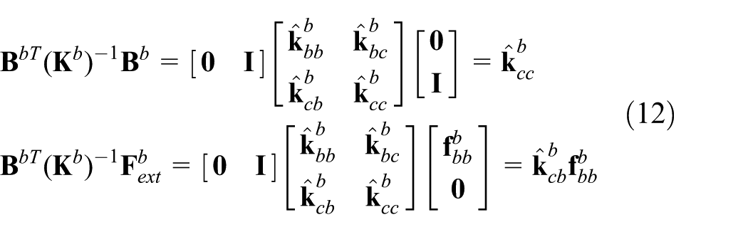
Plugging the above equation into the second equation in equation (7) yields

According to the operation of the Boolean matrix,

where
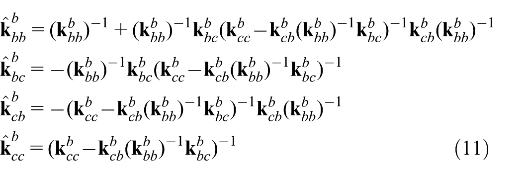
Sub-matrix
Insertion of equation (12) into equation (9), and

Combining equations (6) and (13) produces a set of new coupled equations, which are used to solve the contact behavior in the wear simulation
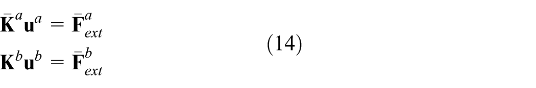
where

In the flops of matrix decomposition (
Finally, this study, through the following procedure, can obtain the contact normal force of equations (2) and (3) to assess the wear results. The steps for implementation of contact normal force are as follows: (1) solve displacement of component a in equation (14), (2) calculate contact forces in equation (13), and (3) derive the contact normal force in equations (2) and (3) by introducing a normal vector

Once the normal force at the contact node is positive, that is, directed outward, the node is under tension, and contact does not occur.
33
Such tensile nodes on the contact region are then excluded through the new Boolean matrix
An implicit formula is then used to integrate equations (2) and (3). The wear volume and wear depth can be written as
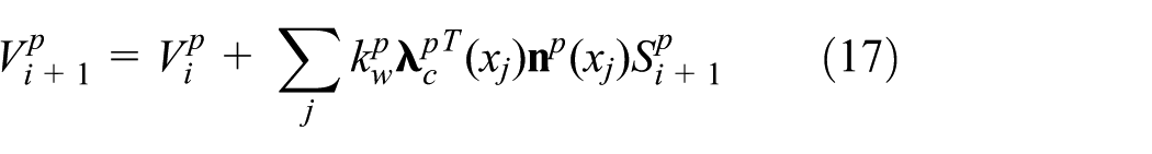

where subscript i is the incremental step index and j is the contact node index.
The second term on the right side of equations (17) and (18) represents the excessive wear results generated at incremental step i + 1 which can be used to estimate the accumulated wear volume and depth of component p at incremental step i + 1 and to update the geometry of the worn components. For most engineering problems, wear is only considered in one of the components. Only the stiffness matrix of the worn component needs to be regenerated and decomposed with respect to its historical states. If there is no worn component b, the matrix of component b can only be regenerated and decomposed at the first incremental step. Thus, this method generates a greater reduction in the computational costs of wear simulation, especially in a larger matrix of component b.
Based on the above considerations, the detection of contact status is illustrated with a flowchart as shown in Figure 1. The process of the proposed incremental method used to implement wear simulation is shown in Figure 2. In each step, the geometry of the worn component needs to be updated and the elements on the contact region varied subsequently. The determinant weighted algorithm is adopted to automatically re-mesh the FE model of the worn component. 35 Furthermore, the linear equation solver in this study is written in Fortran 95 using the skyline algorithm. For a wear problem with different material properties, the normal forces on the contact region can be estimated and the wear volume and wear depth may thus be obtained using this method.

Process of detection of contact status based on MLLM.

Scheme process for the wear simulation.
A geometric model of structures may be constructed by simulating body generation in a computer-aided design (CAD) program. Thus, FE body models that are robust and effective parameterized may be based on the analytically derived mathematical representations of body shapes. The structural analysis of the body model is conducted using FEM with a quadratic isoparametric element. Body profile calculation and mesh generation are conducted automatically using a specially developed software. Figure 3 presents a flowchart of the procedure of the proposed method. The elements are verified by patch test to ensure that the solutions from FEM converge to the exact solution. In this study, the mesh at the contact region is thin, similar to other studies, because automatic mesh refinement processes are applied to achieve the specified accuracy. Elements that pass such a patch test will converge and sometimes display superior performance. Creating 3D FE meshes is usually a labor-intensive and error-prone process. Preprocessors and automatic mesh generation algorithms are beneficial in discretizing 3D objects. A hexahedral eight-node element is used in this study for the elements. The shape of the elements is not significantly long and narrow, thus improving the calculation accuracy and results in stable solutions.

Flowchart of the presented procedure.
Case studies
Pin-on-plate wear simulation
To test this method, the pin-on-plate wear problem is used. The wear results and the CPU time of this method are compared with those of the previous method 7 as shown in equation (5). Here, only wear on the pin is considered, and the pin moves on the plate along a circular route with a radius of 5 mm. The geometry of the model is based on Wu et al., 7 as shown in Figure 4, and the experiment on a pin-on-plate model performed by Saikko 36 was qualitatively compared.

A wear behavior of pin-on-plate and the corresponding FE model.
In this study, the hexahedron linear element is used with three translational displacements at each node to reconstruct the FE models. According to section “Formulation and methodology,” the structure is divided into two components, denoted a and b. The ultra-high-molecular-weight polyethylene (UHMWPE) pin is designated a and discretized into 1331 nodes and 1080 elements. The load applied to the top of the pin is 70.7 N. The 316L ASTM F318 annealed stainless steel plate is designated b and discretized into 530 nodes and 252 elements. The motion of the bottom of the plate is restrained, as shown in Figure 2. The corresponding material properties, Young’ modulus (E) and Poisson’s ratio (ν), are 0.8 GPa and 0.47 for the UHMWPE and 190 GPa and 0.305 for the stainless steel, 7 respectively. For the contact conditions, complete contact is assumed between the pin and plate, as the initial condition. For the wear parameters, the wear coefficient is 0.8 × 10⁻⁶ mm3/N m and the total sliding cycle is 1 million cycles. 7 The stroke length was 10 mm, cycle frequency 1.02 Hz, average sliding speed 20.4 mm/s, and load 70.7 N, giving a nominal contact pressure of 10 MPa with the above pin geometry. 36
When the number of increments is 10, Figure 5 shows the curves of the wear depth for the previous method and this method. In the sliding cycle of 1 million, the wear depth is 0.1395 mm for previous method and 0.1401 mm for this method. When the number of increments is 100, the wear depth of 0.1374 mm in this method is in good agreement with the previous method.7,36

Wear depth of pin by previous method 7 and this method.
In the previous method, the wear volume is obtained from the wear depth which is derived based on a modification of the Archard’s model, that is,
To understand the computational efficiency of this method, the run time seconds for the solution procedure are specified by
Comparing the computational time needed by the method 7 and the proposed method, it is obvious that the latter is superior as shown in Figure 6. For an increment of 1, the CPU ratio of this method is 0.67. After an increment of 10, the CPU ratio gradually decreases and converges to approximately 0.57. When considering the wear of a component, traditional FE procedures must involve repetitive computations on overall structure which need longer elapsed time while addressing larger round-off errors.

CPU ratio of previous method 7 and this method.
Block-on-ring wear simulation
In this section, a commonly used wear problem in engineering design, called block-on-ring oscillation, is investigated. Wear of the ring and the block was demonstrated by Kim et al. 12 Additionally, Bayer 37 observed that the block wear is of primary concern in such wear experiments. In Kim et al., 12 the block tightly contacts the surface of an oscillating ring, and the ring oscillates at ±3° at 5 Hz. Both the block and the ring are made of 4340 Steel with Young’s modulus (E), Poisson’s ratio (ν), and a density (ρ) of 200 GPa, 0.3, and 7.85 × 10⁻³ g/mm3, respectively. For geometric dimensions, the contact area of the block on the ring is 100 mm2. The inner diameter, external diameter, and width in the ring are 23, 35, and 8.7 mm, respectively.
In this study, the FE model of the block is designated a and discretized into 2205 nodes and 1632 elements. A normal force of 470 N is applied to the top surface of the block. The FE model of the ring is designated b and discretized into 18,788 nodes and 14,640 elements. The inner surface of the ring is constrained, as shown in Figure 7. Complete contact is assumed between the block and ring, as the initial condition. The wear coefficient of the block and ring is 1.00 × 10⁻⁵ mm3/N m, the incremental step is 750 cycles, the total number of sliding cycles is 300,000, and the overall sliding distance is 1098.8 m. 12 The reciprocating oscillation is divided into eight computational steps, four for the forward motion and four for the backward motion.

FE model of block-on-ring wear in oscillating contact.
The results of wear simulation from this study are compared with those from Kim et al., 12 listed in Table 1 and shown in Figure 6. Here, the wear mass can be defined as the wear volume multiplied by the density, obtained from equation (17). The maximum wear depth in Figure 8 occurs near the center of the ring, which is 0.0480 mm for this method and 0.0570 mm for the FEM of Kim et al. 12
Comparison of wear results of the block-on-ring test with Kim et al. 12

FEM: finite element method.

Distribution of wear depth on an oscillating ring.
Comparing the computational time needed by the method 7 and the proposed method, the run time ratio is determined via equation (19) and the CPU ratio is presented in Figure 9. As the increment is 1 to 40, the CPU ratio reaches 0.638 for the proposed method. As one can see from the figure, differing from the previous case, the CPU ratio performs a straight-line because the bearing wear is caused on both sides of the contact zone, block and ring.

Results of CPU ratio Φ for block-on-ring wear simulation.
Metal-on-plastic artificial hip joint wear simulation
Furthermore, in order to demonstrate the accuracy and the efficiency of the proposed method, a complex wear problem in bioengineering, the artificial hip joint wear problem, is also investigated. Here, the metal-on-plastic hip joint is used for analysis and the results presented are compared to the available simulation data.7,23 Comparing the computational time needed by the method 7 and the proposed increment approach, it is obvious that the latter is much superior in cases of large sliding distances.
In this article, the FE model of an artificial hip joint is constructed using three components: backing, acetabular cup, and femoral head. 7 The backing is composed of compact bone, the acetabular cup is composed of UHMWPE, and the femoral head is composed of stainless steel. The corresponding material properties are as listed in Table 2. For geometric dimensions, the cup has an interior diameter of 22 mm and a thickness of 10 mm. The outer diameter of the femoral head is 22 mm. In the FE model, the backing and acetabular cup are designated a and discretized into 3702 nodes and 2940 hexahedron linear elements, where the elements of the outermost layer are the backing model. The hollow femoral head is designated b and discretized into 1906 nodes and 924 elements, as shown in Figure 10.
Material properties. 7
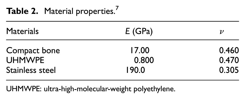
UHMWPE: ultra-high-molecular-weight polyethylene.

FE model of artificial hip joint and loading directions for 16 stages in a gait cycle.
The loadings applied to the artificial hip joint are identical to those adopted by Wu et al. 7 Here, the wear path of the artificial hip joint only considers flexion/extension motion,7,15 the maximum load is 3.5 kN, the maximum swing angle is 23°, and the gait cycle is divided into 16 periods of loading with different angles, 9 forward and 7 backward, as shown in Figure 10. The motion of the interior surface of femoral head is constrained, and the initial contact region is assumed between the acetabular cup and femoral head. From Wu et al., 7 where only the acetabular cup is worn, the wear coefficient of 0.8 × 10⁻⁶ mm3/N m for the acetabular cup is used. A rate of 1.5 million gait cycles per year is assumed in assessing the wear results of the cup, and increments of 10 are adopted to implement the current wear simulation.
Figure 11 shows the growth of wear depth and volume of the acetabular cup for 1.5 million gait cycles. The corresponding linear and volumetric wear rate is listed in Table 3, while the results of the literature are also listed here.

Wear depth (mm) and wear volume (mm3) of the acetabular cup.
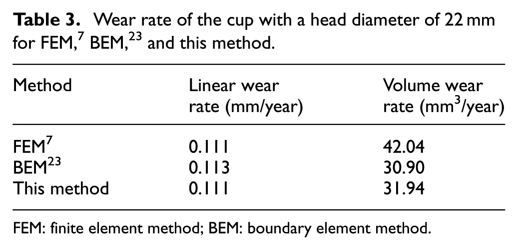
FEM: finite element method; BEM: boundary element method.
Similarly, the comparison of CPU ratio is shown in Figure 12 and wear depth contours of the acetabular cup are illustrated in Figure 13. From the figure, one can find that when the increment is 10, the CPU ratio approached 0.1264. The efficiency is quite significant because only the acetabular cup FE matrices are updated.
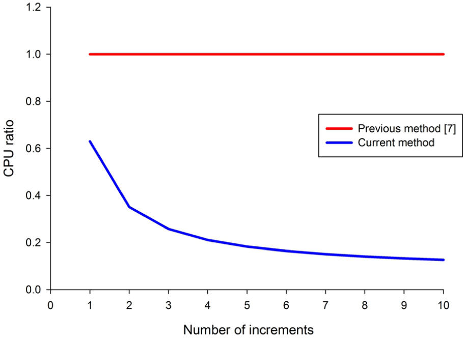
Results of CPU ratio Φ for artificial hip joint wear simulation.

Wear depth (mm) contours of the acetabular cup.
Discussion
In the simulation results, compared with the block-on-ring simulation of Kim et al., 12 the current wear mass is approximately 6.04% lower for the block and is approximately 6.59% higher for the ring. The current wear depth is approximately 4.85% lower for the block and is approximately 7.94% higher for the ring. The FE model of Kim et al. did not use proper symmetric boundary conditions as in Wu et al., 38 which may account for the difference. In the FE model of the artificial hip joint, Table 3 shows the linear wear rate of this study is in good agreement with the literature.7,23 In the volumetric wear rate, this result is approximately 24.02% lower than Wu et al., 7 and approximately 3.37% higher than Sfantos and Aliabadi. 23 However, Sfantos and Aliabadi 23 observed that the wear volume in Wu et al. 7 was calculated using an incorrect numerical method. Thus, the difference in Wu et al. 7 is not discussed here. In Sfantos and Aliabadi, 23 the wear volume was calculated using a Gaussian quadrate, a method which has been shown to be erroneous in Hunter. 39 In contrast, the proposed method does not need to use numerical integration methods. Thus, the difference of 3.37% may result from the numerical integration error. The wear volume determination is significantly better than with complex volume formulation or numerical integration methods, and the calculation of wear volume is fast and easy.
In the computational efficiency of wear simulation, several studies have addressed the computational costs of the wear simulation. Sfantos and Aliabadi 19 proposed an optimal increment formulation with shape optimization which was approximately eight times faster. This is equivalent to a computation time of 0.125 times shorter than the classic incremental method. Sfantos and Aliabadi 22 also used an incremental formulation with an optimal time step, to obtain a computation time of roughly 0.26 times shorter than the classic. Bae et al. 25 used a substructure method to obtain a computation time of approximately 0.5 times shorter than the conventional FEM. Parallel computation was proposed using FEM by Mukras et al. 20 to minimize the computational costs and to obtain a computation time of 0.3 times shorter than the intermediate update procedure. Although these methods have successfully reduced the computational costs, their application is unclear and time-consuming. Moreover, the residual error resulting from large matrix operations may exist.
Given the abovementioned reasons, this study proposed an alternative and efficient FEM to reduce computational costs and portioned the whole structure into two components to avoid a larger matrix operation. In the pin-on-plate wear simulation, the computation time of the current contact calculation is approximately 0.63 times shorter than the previous method, 7 as equation (5). This is because the number of flops of the matrix decomposition is significantly fewer than in the previous method, which is that this method requires 2.26 × 10¹⁰ flops less than the previous method. Compared with the computation time of overall wear simulation of previous method, the computation time of this method is approximately 0.53 times shorter, as shown in Figure 4. This is equivalent to half the CPU time of the previous method. Because wear is only considered in one of the components, only the matrix of the worn component needs to be regenerated and decomposed with respect to its historical states.
For the case of single wear between components, this approach appears to be superior in the reduction in computational costs, especially for the case of no worn component b. For example, in the block-on-ring wear simulation, when only the block is worn, the computation time is approximately 0.076 times shorter than when both the block and ring are worn. In the metal-on-plastic artificial hip joint wear simulation, when only the acetabular cup is worn, the computation time is approximately 0.201 times shorter than when both the cup and femoral head are worn. In other words, the matrix size of component b may make a difference in the reduction in computational costs. The computation time of the overall in-core solving procedure becomes significantly shorter than in the previous or classic methods. This reduction occurs because (1) the number of flops of the matrix decomposition is fewer than in previous methods and (2) the structural system is partitioned into two independent systems, meaning that the updating geometry and matrix regeneration and decomposition on the worn components can be individually implemented. When only component b is not worn, the reduction in the computational costs of the wear simulation using this method is even greater, especially when the matrix of unworn component b is larger.
Conclusion
This study reveals that the proposed method can improve the simulation efficiency of structural wear. The contact transformation is employed to avoid the calculation of whole structural matrix. For instance, decomposition on either
This article focused on improving the computational efficiency. The strain energy is completely transferred through the contact regions of substructures; only variables on the contact surface are involved in the solution procedure, which are the most costly repetitive steps during simulation. Thus, the round-off error is tremendously reduced and the repetitive procedure can be processed precisely and fast. For the case of single wear between substructures, this approach appears to be superior in the computational process.
Footnotes
Academic Editor: Nao-Aki Noda
Declaration of conflicting interests
The author(s) declared no potential conflicts of interest with respect to the research, authorship, and/or publication of this article.
Funding
The author(s) disclosed receipt of the following financial support for the research, authorship, and/or publication of this article: The authors acknowledge supports from the NSC of ROC Grant No. 99-2221-E-005-048-MY3 and the Mechanical and System Research Laboratories, Industrial Technology Research Institute in Taiwan.