
Abstract
This article presents the correlation of vibration signal feature, that is, displacement due to vibration (microns) during the machining and three-dimensional finite element simulations in tool wear monitoring of a metal turning operation. Machining of AISI 1040 has been carried on using an uncoated inserts and online vibration signals acquired using a laser Doppler vibrometer. The measured tool wear forms correlate to features in the vibration signals in frequency domains. Analyses of the results suggested that the vibration signals’ features are effective for use in cutting tool wear monitoring and wear qualification. Present work demonstrates the three-dimensional finite element analysis to predict the workpiece displacements in feed direction and corresponding tool wear with the help of induced vibrations in face turning under dry machining conditions. Vibration-assisted turning model is developed and validated by comparing the simulation results with experimental results. In this research, three-dimensional finite element modelling and simulation issues for vibration-assisted turning are explored in detail. Machine dynamic effects are taken into account to predict the outcomes such as tool wear displacements and chip formation. The model can be implemented in an online tool wear monitoring system which predicts the actual state of tool wear in real time by correlating displacement variations during the machining. The correlation between the displacement due to vibration and flank wear has been evaluated through three-dimensional finite element modelling and simulation. Comparisons of simulations with experimental results demonstrate their predictive capability. From the results, useful conclusions may be drawn, and it can be stated that the proposed models can be used for industrial application.
Keywords
Introduction
Vibration in cutting tool due to machining condition is one of the most important technological parameter because it can significantly influence on tool wear and life, quality and residual stresses of machined surface and cutting force. Therefore, it is necessary to study the effect of cutting tool vibrations during the machining. When the workpiece is subjected to vibration during the machining under various cutting conditions, it causes the relative displacement between tool and workpiece, which generates the vibration of the cutting tool. The dynamic phenomena of cutting tool induced by the interaction of an elastic system in the cutting process causes the relative displacement between tool and workpiece, which generates the vibration of the cutting tool. 1 Mechanism of regenerative chatter in facing operation is presented in Figure 1 for better understanding of mechanistic system. 2
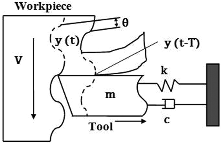
Face turning system for simplified single-degree-of-freedom regenerative effect. 2
Vibration of the tool can be a good way to monitor online growth of the tool wear in turning, and therefore, it can be useful for establishing the end of tool life in these operations. Especially, the relative vibrations of cutting tool and workpiece cause the poor machined surface roughness, poor dimensional accuracy of the workpiece and abnormal tool wear or tool breakage, which lowers down the productivity and increases the cost of production. 3 Therefore, it is necessary to study the effect of cutting tool vibrations during the machining. At present, some experimental measurement methods were used to evaluate the vibration field, including accelerometers and laser Doppler vibrometer. Most methods essentially involve processing information such as acoustic emission, tool tip temperature, vibration signatures (acceleration signals), cutting force and so on. However, acousto-optic emission methods have been recently introduced as a reliable way to detect the vibration amplitudes with non-contact mode to identify the corresponding tool wear. 4
Tounsi and Otho 5 identified the relative vibration condition, passing among the official document, cutting tool, chuck and workpiece during the machining. They have reasoned out that vibration is an inextricable part, and it has detrimental effects on the quality of machined surfaces. Chen et al. 6 found that the relative vibrations of cutting tool and workpiece cause the poor machined surface roughness, poor dimensional accuracy of the workpiece and abnormal tool wear or tool breakage, which lowers down the productivity and increases the cost of production. Bonifacio and Diniz 7 carried out the experiments for correlating the variation of the tool vibration, tool wear, tool life and surface roughness in the finish turning with the coated carbide tools. Dimla 8 described a tool wear monitoring procedure in a metal turning operation using vibration features. The monitoring procedure revealed that the vibration signals’ features relate to the wear qualification of cutting tool wear. In modern machining processes, 9 due to continuous demand for higher productivity and product quality, better understanding and control of the machining process are required. A better understanding can be achieved through finite element (FE) modelling and simulations of machining process. Therefore, in late years, finite element method (FEM) has particularly become the principal tool for simulating metal cutting operations. Predictions of the physical parameters such as displacement due to vibration, tool wear, cutting forces, tool chip interface temperature and stress distributions accurately play a pivotal role in the prediction process engineering of machining processes.
Simulations of various machining operations using the FEM have been reported over the last three decades; in Mamalis et al. 9 and Mackerle, 10 a collection of such articles can be found. Ostasevicius et al. 11 developed a FE model of the vibration milling tool and verified experimentally. This example handles the creature as an elastic pre-twisted structure (mill cutter) characterized by its natural vibration modes. Ostasevicius et al. 12 described an approach for the reduction of surface roughness based on exciting higher-order transverse modes in the vibration turning tool. The research methodology employed in this work is based on the combined numerical–experimental approach. Özel and Zeren 13 proposed a FEM model and simulation strategy for orthogonal cutting of AISI 1045 steel using dynamic explicit arbitrary Lagrangian–Eulerian (ALE) method thereby simulating plastic flow around the round edge of the cutting tool and to meet the demand for chip separation criteria. Grzesik 14 created a FEM simulation model in order to obtain numerical solutions of the cutting forces, specific cutting energy and adequate temperatures occurring at different points through the chip/tool contact region and the coating/substrate boundary for a range of coated tool and uncoated tool materials and defined cutting conditions. Yen et al. 15 developed a methodology to predict the tool wear evolution and tool life in orthogonal cutting using FEM simulations. Attanasio et al. 16 deal with the 3D finite element simulation (FES) of cutting procedures in order to estimate tool wear development during turning operations. In particular, a new procedure for tool wear calculation and tool mesh and geometry updating has been proposed in a commercial 3D code. Maňková et al. 17 identified the influence of cutting parameters in hard turning of hardened steel with hardness of HRC 55 with mixed oxide ceramic inserts. Wei and Chuan-qiong 18 presented the construction of a 3D FES of turning process with an updated Lagrangian method.
Most of the research study is confined to experimental results, but, likewise, the modelling of face turning can provide useful data for better discernment of the procedure. Numerical modelling and, particularly, the FEM have been widely applied in the past for the analysis and the prognostication of the cutting performance in machining operations. FEM has been a very potent tool in the cutting technology and can be given to high-speed hard turning as well. Even if the implementation of such models in FE software could serve in the prediction of the crater and flank tool wear, only few research articles are available on this topic and, what is more, are mainly focused on two-dimensional (2D) problems. Consequently, tool wear prediction and tool substitution policy are looked as very important tasks in order to maximize tool performance and minimize cutting costs. Most of the modelling work published so far pertains to 2D models of orthogonal cutting, while 3D models are rather uncommon in the relevant literature. That is mainly because, even though 3D cutting is more realistic, since cutting is 3D in nature, it requires a much more complex consideration of workpiece and cutting tool geometry, contact properties and, of course, additional computational time. A considerable measure of research has focused on 2D FESs for turning, but works on 3D FESs for turning process are not widely available.
The major drawback of a cutting simulation is that it does not provide direct information on the increase of tool wear, as opposed to the experimental approach. 19 However, it is expected that the tool wear growth (crater and flank wear) is dependent on the relative displacement between workpiece and cutting tool is due to vibration, cutting temperature, contact stresses and sliding velocity produced during cutting. In order to overcome the above-mentioned limitations and to improve the performance of FESs, 3D FE models can be effectively used to simulate actual machining processes despite of the calculation time for FESs in case of turning process. The tool displacement model, governed by these process variables, the distribution of vibrations along the workpiece, may be effectively estimated. From the available literature, it can be concluded that 3D FESs in face turning offer several advantages compared to 2D FESs. Although 2D FESs are utilized in machining, they are not much used in face turning, the obvious cause being the difficulty in 3D modelling of machining process. However, studies on 3D FES for face turning process by considering the effect of cutting tool vibrations are not widely available. Serious attempts have been given by various research groups in India and abroad to explore the force of vibrations in hard turning using the 3D FES. Hence, an extensive investigation on the issue of cutting tool vibrations in face turning processes is significant to gain an accurate FES method for the vibration-assisted machining (VAM). Finally, these FESs can be evaluated with experimental results using empirical relations. When employed efficiently, FE modelling and simulations aid in attaining the above objectives in machining applications.
In the present work, investigation primarily focuses on preparing a 3D FES-based methodology to forecast the development of vibration displacement and tool wear in face turning. Specifically, the research tasks include generation of appropriate experimental data and correlate the results with a 3D FE simulation model for tool wear so as to look into the influence of cutting tool vibrations under the various cutting conditions. Implementation of machining model(s) in the commercial FEM code (Deform®-3Dv6.1) relates the displacement and tool wear during machining to the predicted process variables. Results show the good degree of agreement between experimental and simulated values in predicting worn tool profiles at different cutting conditions.
Proposed methodology in the present study
Machining is started with a fresh tool continued until the tool failed or the cutting edges were severely worn, when continued cutting risked catastrophic failure. The duration of each test allowed complete stabilization of the cutting process to be attained while allowing for significant tool wear. Measurements of flank, nose and notch wear lengths are created after the vibration signals had been registered using a tool maker’s microscope. A PolyTech 100-V laser Doppler vibrometer is employed to record the vibration signals and then fast Fourier transform (FFT) analysis is performed to convert the time domain signal into frequency domain. Turning operation is a steady-state process when continuous chip is formed. A tool wear estimation model has been developed for turning operation as part of the work. It includes the calculation of wear rate at steady state, the searching method of a suitable cutting time increment, the calculation of nodal displacement due to wear and tool geometry updating. Overview of proposed methodology in present study is presented in Figure 2.
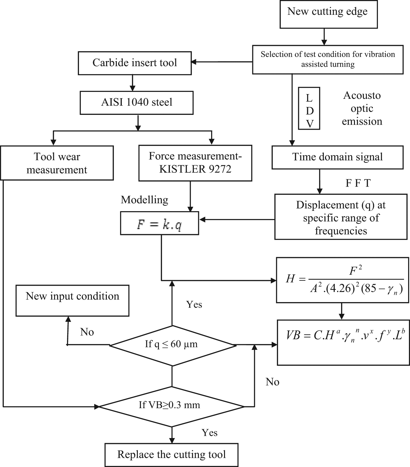
Proposed methodology in this study.
Experiments have been conducted on PSG-124 lathe at constant cutting conditions. This machine has both auto feed and variable spindle speed capabilities. Experimental set-up on lathe machine is shown in Figure 3. A PolyTech 100-V laser Doppler vibrometer with data acquisition system is kept at constant distant from the machining zone to measure the displacement during cutting operation. Laser is focused on the rotating workpiece during machining. A Kistler® 9272 four-component dynamometer with a multichannel analyser used for cutting force acquisition and discussion about cutting force signals is intentionally not discussed in detail.
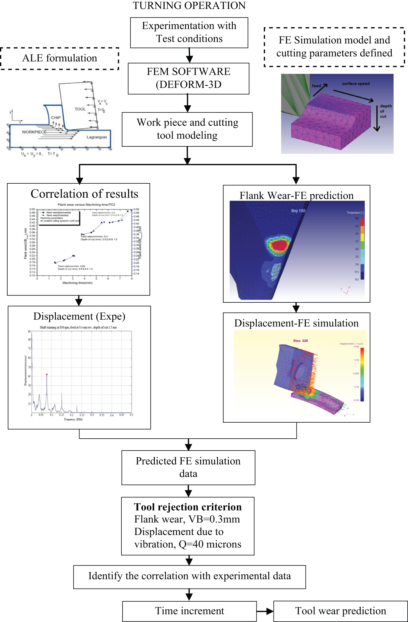
Strategy for results analysis in the present work.
Cutting parameters used in the machining are as follows: rake angle (°): −5, clearance angle (°): 5, flank face length (mm): 0.75, rake face length (mm): 1. Specifications of the machine: PSG lathe, PSG India; type of bed: straight, single V, length of bed: 2.1 m, swing over the bed: 21 cm, swing over the carriage: 14 cm, length between centres: 96 cm; variable spindle speed: 63–1250 r/min; motor capacity: 10 hp; tool post: square-headed chuck type: four jaw and make PSG India. Face turning experiments are performed by PSG lathe with uncoated tungsten carbide insert DNMA 432 by Sandvik. Tool holder used in the experiment is DDJNR. Test samples made of AISI 1040 steel, with 80 mm diameter and 150 lengths, are prepared in order. The cutting conditions are selected based on the toughness of the workpiece within the tool manufacturer’s recommended range for the workpiece–tooling geometry configuration. The tests are conducted at the following cutting conditions: cutting speed (N): 538, 836 and 1135 r/min; feed rate (f): 0.08, 0.4 and 0.8 mm/rev; and depth of cut (d): 0.5, 0.8 and 1.5 mm. Figure 3 gives the strategy followed in the results analysis as part of experimental evaluation. The cutting parameters are selected according to the tool supplier’s recommendation for tool and workpiece combinations. Cutting tests are conducted at dry machining conditions. Cutting velocity and feed rates are selected based on the tool manufacturer’s (Sandvik) recommendations for workpiece material and tool combination.
Tool rejection criterion was adopted based on both ISO 3685 and ISO 10816 standards to evaluate the cutting tool condition in turning. To examine the performance of the cutting tools at various machining conditions, an experimental set-up for face turning operation was also proposed, and it is presented in Figure 4. Due to the presence of dominant signals, vibration is measured in the feed direction (Y direction).
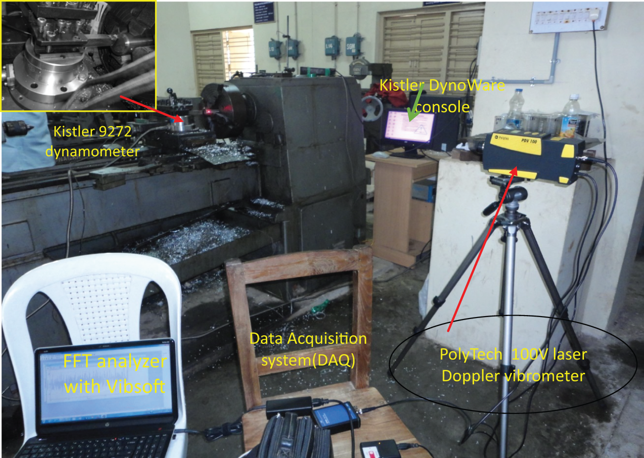
Test rig for experimental set-up.
A PolyTech 100-V laser Doppler vibrometer with data acquisition system is kept at constant distance from the machining zone to measure the displacement during cutting operation. Laser is focused on the rotating workpiece during machining. The vibration raw signals are gathered in time domain called waveform graph and then converted to frequency domain called spectrum graph by an in-built FFT analyser. The spectrum graph provides more information about machining process than the waveform graph. The vibration parameter used to analyse the vibration signal in frequency domain is displacement. All the time domain signals in the present work are filtered using a 0- to 500-Hz band pass filter, and signal processing involves signal blocks of 4000 data points collected over a sampling interval 500 ms. Before each cut, the worn edge was removed by a new one to avoid any influence of wear. Displacement is considered as the vibration parameter for the analysis in this study. Tool rejection criterion: As per ISO 10816 for vibration severity standards, displacements in rotating cutter up to 20 μm do not have any effect on tool flank wear. Tool flank wear is found to be effected by the measured displacements in the range between 20 and 60 μm. A displacement value beyond 60 μm is not an acceptable as per ISO 10816.
3D FE modelling and simulation of turning process
The 3D model, implemented in DEFORM 3D v6.1, is reported in Figure 5, where it is possible to see the workpiece with the growing chip and the tool. In the present work, the cutting tool assumed to be 20 as rigid object meshed with more than 75,000 elements is oriented according to the cutting angles set in experimental test conditions selected, and it moves along a linear direction. The workpiece, considered as a rigid elastoplastic object meshed with more than 30,000 elements, is fully constrained on the lower and lateral sides so that it cannot move. The friction is modelled considering a shear factor equal to 0.6. An adaptive re-meshing scheme is implemented to optimize between the computational time and accurate prediction. The base of the workpiece is constrained in all directions. The tool is subjected to move in Y direction at three different constant speeds and constrained against movements in X and Z directions. A commercial software code, Deform 3Dv6.1 and it is an explicit dynamic ALE modelling approach is used to conduct the FEM simulation for oblique cutting by considering round tool edge geometry are successfully implemented in the model. The chip formation is simulated via adaptive meshing and plastic flow of work material. Therefore, there is no chip separation criterion needed. In this approach, the elements are attached to the material, and the undeformed tool is advanced towards the workpiece.
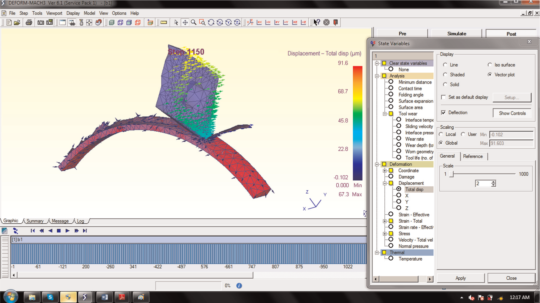
Deformation in turning process (displacement due to vibration).
The software code is used for modelling and simulating the cutting process capable of performing coupled thermo-mechanical transient analysis. The thermo-mechanical FEM simulation schemes (models) are created by including tool and workpiece thermal and mechanical properties, boundary conditions and contact conditions between tool and workpiece, and one of the FES scheme models is shown in Figure 5. As discussed in the literature, this research is aimed to the 3D numerical prediction of tool wear using the knowledge acquired in 2D studies. Thus, in order to validate 3D predictions for both flank and displacement due to vibration, a series of experiments have been carried out in turning.
Results and discussions
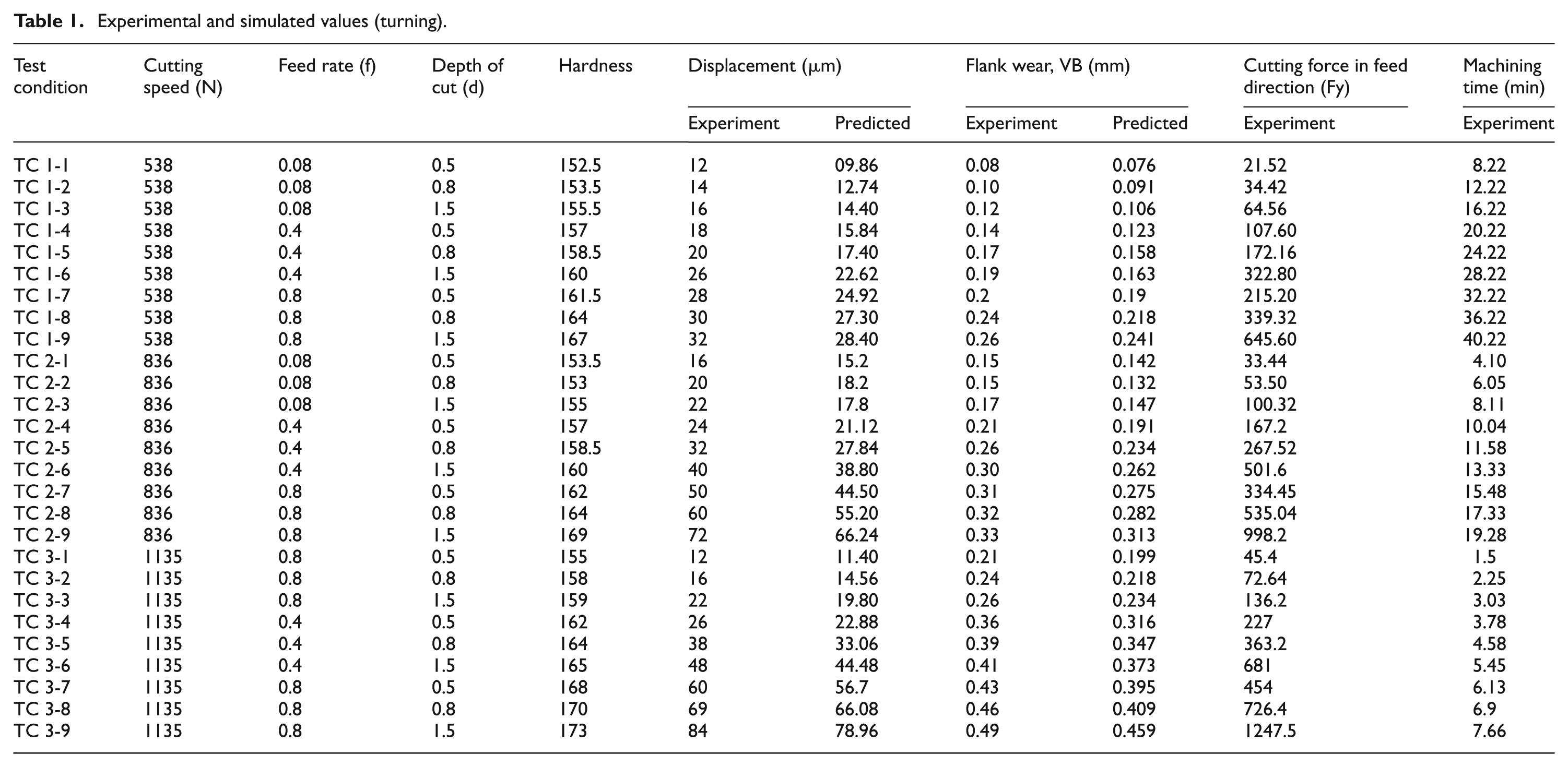
As part of the present work, FESs have been carried out for 27 cases of experiments consisting of three different feed rates, cutting speeds and depth of cuts. Table 1 presents results of both experimental and predicted FES values at different test cutting conditions for which simulations are carried out. In all simulations, it is made sure that steady state condition has reached and some more data are collected after that time. Displacement due to vibration, chip morphologies and tool wear are predicted by FESs. Predicted FE results are evaluated with experiment results. In FESs, the resultant field variables have been extracted after 5 ms of cutting time. This short cutting time is assumed sufficient for the field variables to reach a steady state from the literature. Displacements obtained from FE model of metal cutting process are also in agreement with the results of experiment. It is a known fact 21 that the friction between the tool and the workpiece is little when the tool is new (sharp) and accordingly, the amplitude of vibration will also be low. Spectrum graphs for the vibration signal are generated using Vibsoft FFT analyser. Spectrum graphs for experimental vibration signal in every test condition are presented in Figures 6(a), 7(a) and 8(a). Predicted displacement in every test case is shown in Figures 6(b), 7(b) and 8(b). Measured values (experimental tests) and predicted values (FESs) are shown in Table 1, and correlation between flank wear and machining time in all conditions are presented in Figures 6(c), 7(c) and 8(c). Effect of displacement due to vibration on tool wear is significant and clearly identified in all test conditions. Correlation between displacement and tool flank wear is analysed in FESs, and corresponding FE predicted tool wear profiles are presented in Figures 6(d), 7(d) and 8(d). As per ISO 10816 for vibration severity standards, displacements in rotating cutter up to 20 μm do not have any effect on tool flank wear.
Experimental and simulated values (turning).
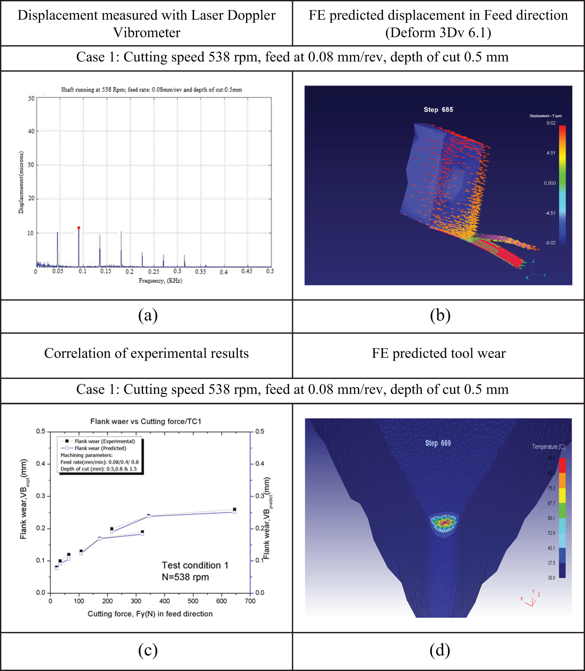
(a) Displacement due to vibration, (b) FE predicted displacement, (c) flank wear with time and (d) FE predicted tool wear.
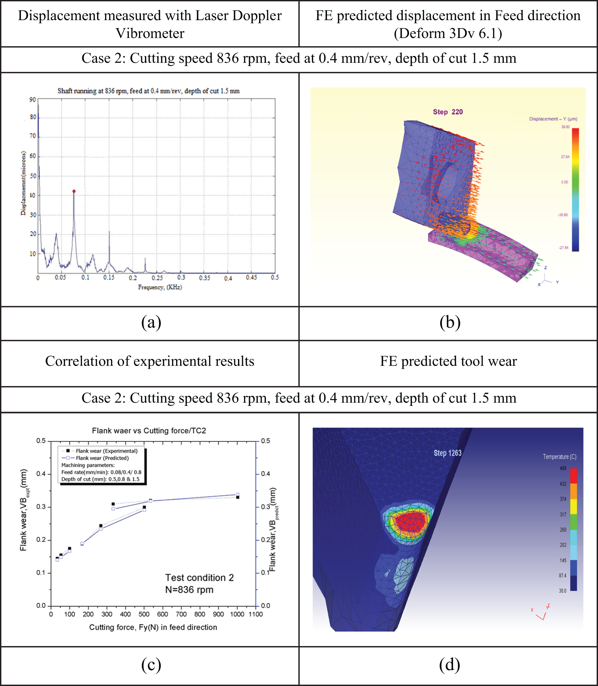
(a) Displacement due to vibration, (b) FE predicted displacement, (c) flank wear with time and (d) FE predicted tool wear.

(a) Displacement due to vibration, (b) FE predicted displacement, (c) flank wear with time and (d) FE predicted tool wear.
Cutting speed of 538 r/min, feed at 0.08 mm/rev and depth of cut of 0.5 mm (case 1)
From Table 1, it is clear that in all conditions, that is, in test condition 1, displacement values are found to be less than 60 μm and VB ≤ 0.3 mm. Figure 6(d) shows the simulated tool flank wear corresponding to initial point of the test for each of the cutting conditions for AISI 1040. It is observed that as long as values of VB ≤ 0.14 mm, the tool flank wear developed gradually without any built-up edge (BUE) formation.
Cutting speed of 836 r/min, feed at 0.4 mm/rev and depth of cut of 1.5 mm (case 2)
Results for the test condition 2 are presented in Figure 7(a)–(d). In Figure 7(a), an increase in displacement due to vibration is found. In face turning, as the length of the workpiece decreases, the stiffness of the workpiece increases, and a corresponding increase in vibration will occur and is clearly observed in Figure 7(a). Corresponding FE predicted displacement is shown in Figure 7(b). This increased level of vibration is due to increase in tool wear, and this phenomenon is clearly identified based on correlations in Figure 7(c). Increase in tool wear is predicted with FESs and is presented in Figure 7(d). It is observed that when the flank wear (VB) values reaches to 0.2 mm, then possibility of for the formation of workpiece built up on the edge and material smearing on the flank wear face will be increased. It is observed that as long as values of VB ≥ 0.25 mm, the tool flank wear gradually developed with significant BUE formation. In the cutting process, the resistance force acting on the cutting tool is mainly generated by the status of feed rate and depth of cut. The increase of cutting depth causes the increase in the resistance force at the tool tip, which excites more vibration appearance.
Cutting speed of 1135 r/min, feed at 0.8 mm/rev and depth of cut of 0.8 mm (case 3)
Results for the test condition 3 are shown in Figure 8(a)–(d). In Figure 8(a), a further increase in vibration amplitude is found when compared to previous two cases, and this is because of the increasing friction between the workpiece and cutting tool which is due to increase in tool wear. Any displacement beyond 60 μm value leads to excessive vibration which can reduce the tool life. Figure 8(b) shows the highest FE predicted displacement in all test cases presented in section ‘Results and Discussions’. Correlation between flank wear with respect to machining time in test condition 3 is shown in Figure 8(c), and profile of 3D tool flank wear after simulation is presented in Figure 8(d). At the end of the simulation, it is found that values of VB ≥ 0.3mm the tool flank wear and this is a clear indication for the end of the tool life as per ISO 3685 standard. With increase of flank wear, vibration during cutting increases but the rate of increase is lower at higher cutting speeds. As it can be observed from Table 1, the tool life is reduced significantly with the increasing vibration amplitude at all test conditions. As seen above, the axial vibration amplitudes in feed direction obviously increase with increasing feed rate. In face turning process, the vibration stability of cutting tool affects the tool wear and tool life. Further increase in the feed rate causes the excited vibration appearance to appear more discontinuous chip.
Conclusion
According to the visualized time domain vibration data obtained from the experiments for various cutting conditions in Table 1, it is found that the average overall values of Y-axial and Z-axial vibration amplitudes have been enlarged by 64.71% and 5.28%, respectively, as compared with those of the X-axial vibration amplitude. As the results of analysis discussed above, all vibration amplitudes are principally influenced by both the feed rate and cutting depth. The analysis and correlation of vibration signal features to cutting tool wear have been carried out. Frequency-based features correlated well with the tool wear. Based on the measurements of cutting tool wear form and the analysis of the vibration signatures, it has been possible to identify the trend of the sensor signals as the insert wear length increased.
In this work, 3D FESs of face turning of a continuous chip material have been performed in order to provide useful guidelines for the 3D FESs of turning process. Correlation between 3D FESs and experimental results has proved that the approach is able to identify any existence of displacements due to vibrations in face turning process and their effect on the tool wear. Currently, the authors are undertaking well-designed substantial cutting trials and simulations to further verify the approach developed potentially applied to hard materials like titanium- and nickel-based alloys in different machining processes, and the results will be presented in other articles in the near future.
Footnotes
Acknowledgements
The authors would like to acknowledge Dr. R V S Subrahmanyam Scientist ‘G’ & Associate Director, CNC Center NSTL, Visakhapatnam, India for providing both computational and experimental support.
Declaration of conflicting interests
The authors declare that there is no conflict of interest.
Funding
This research received no specific grant from any funding agency in the public, commercial or not-for-profit sectors.