
Abstract
Due to the compressibility of air, non-linear characteristics, and parameter uncertainties of pneumatic elements, the position control of a pneumatic cylinder or parallel platform is still very difficult while comparing with the systems driven by electric or hydraulic power. In this article, based on the basic dynamic model and descriptions of thermal processes, a controller integrated with online parameter estimation is proposed to improve the performance of a pneumatic cylinder controlled by a proportional valve. The trajectory tracking error is significantly decreased by applying this method. Moreover, the algorithm is expanded to the problem of posture trajectory tracking for the three-revolute prismatic spherical pneumatic parallel manipulator. Lyapunov’s method is used to give the proof of stability of the controller. Using NI-CompactRio, NI-PXI, and Veristand platform as the realistic controller hardware and data interactive environment, the adaptive robust control algorithm is applied to the physical system successfully. Experimental results and data analysis showed that the posture error of the platform could be about 0.5%–0.7% of the desired trajectory amplitude. By integrating this method to the mechatronic system, the pneumatic servo solutions can be much more competitive in the industrial market of position and posture control.
Keywords
Introduction
It is well known that there are three major driving types of position servo controls, which are electric, hydraulic, and pneumatic. Due to the linear characteristics and stiffness advantage, higher precision can be obtained using electric or hydraulic cylinders and valves when comparing with the pneumatic ones. But since the compressed air is a low-cost and clean energy, it is still attracting researchers to study on pneumatic position servo control and improve the precision. Compared with feedback linearization,1,2 robust H-∞ control, 3 self-tuning control, 4 sliding mode control (SMC), 5 and fuzzy control, 6 M Smaoui et al. 7 proposed a robust controller based on back-stepping method and obtained better performance.
With the developments of parallel mechanism theories, the parallel platforms driven by electric motors or hydraulic cylinders have been successfully industrialized, especially in the fields of motion simulation and robotic applications, such as 6-degrees of freedom (DOFs) Stewart platform and Delta robot. Some of these platforms were driven by pneumatic elements. K Grewal et al. 8 established a pneumatic parallel system used linear quadratic Gaussian (LQG) controller. The control schemes experimental results showed LQG giving slightly better performance. 9 M Ramsauer et al. 10 proposed a pneumatically driven Stewart platform used as fault detection device. J Pradipta et al. 11 used immersion and invariance method with an additional friction compensator applied for motion control. Generally, the control errors were no smaller than 5%. B Andrievsky et al. 12 described the design features of pneumatic platform for driving simulator while using SMC and switching valves. Simulation results of SMC was about 5% and the experimental results of on-off logic control was about 20%. However, for the most ordinary pneumatic cylinders with typical friction properties and their applications, which are used most widely in the industrial systems, some studies still have to be done about the servo control algorithm.
Meanwhile, some insufficient DOF systems which have the freedoms of roll, pitch, and heave have been used in the motion simulators and virtual reality equipment industry. One of them is three-revolute prismatic spherical (3-RPS) manipulator and lots of extensive studies have been done in the past years.13–15 For the dynamic modeling and control methods studies, G Pfreundschuh et al.
16
presented the mechanics, design, proportional-derivative (PD) control, and experiment results for a 3-RPS platform. YM Cheng and YS Chen
17
investigated an angle trajectory tracking of a 3-DOF pneumatic motion platform, and fuzzy system was used in the trajectory pre-compensation. The angle trajectory following error was about 10%. However, the
Adaptive robust control algorithm was first proposed in 1990s by B Yao and M Tomizuka.18,19 Then, this theory has been fully developed by the presented indirect adaptive robust control (ARC), 20 integrated direct/indirect ARC, 21 and synthesis-based ARC. 22 The applications of these algorithms are quite successful on the studies about linear motor high accuracy control,23,24 hydraulic systems, 25 and vehicle active suspension systems.26,27 In the field of pneumatic servo control system, X Zhu et al.28–30 and G Tao and H Zuo 31 used pneumatic muscle to obtain a much higher performance by applying ARC. The modeling research of pneumatic muscle also attracts some researchers to establish a more accurate model of this element. 32 However, the pneumatic muscle can only bear one-directional tensile force, which means it cannot be used in heavy load conditions under compression forces. Recently, D Meng et al. 33 proposed an adaptive robust method to control a low-friction pneumatic cylinder with 25 mm diameter and 1/8′ proportional valve, which got an adequate performance. Indirect ARC can improve the parameter estimation accuracy and direct/indirect ARC can also improve the transient performance with the fast switching output feature for proportional valves with dead zones. However, for the pneumatic manipulator used as the motion simulator, the vibration caused by the switching characteristic might be a disadvantage. So, to overcome the strong non-linearities and parameters uncertainties of pneumatic manipulator driven by cylinders and inhibit the probabilities, indirect adaptive robust control should be an effective approach in this case.
In this article, an adaptive robust controller is proposed to achieve much higher precision based on the back-stepping method. First, the modeling of the pneumatic servo system of single cylinder is introduced. Then, online parameter estimation methods for single cylinder system are discussed in the next section, as well as the proof of stability. In section “Parallel system structure and analysis,” the kinematic analysis of the 3-RPS mechanism is demonstrated and the controller is expanded to the conditions of parallel trajectory control. Experimental results on different conditions are shown in sections “Single cylinder control experiments”, “3-RPS manipulator posture control experiments,” and “Performance analysis and conclusion.”
Modeling of single cylinder system
The single cylinder servo system considered in this article is shown in Figure 1. A cylinder attached with a position sensor is connected to a proportional valve. The controller hardware is based on NI-cRIO system. In order to simplify the descriptions of modeling and controller design, some of the key symbols are listed in Table 1.
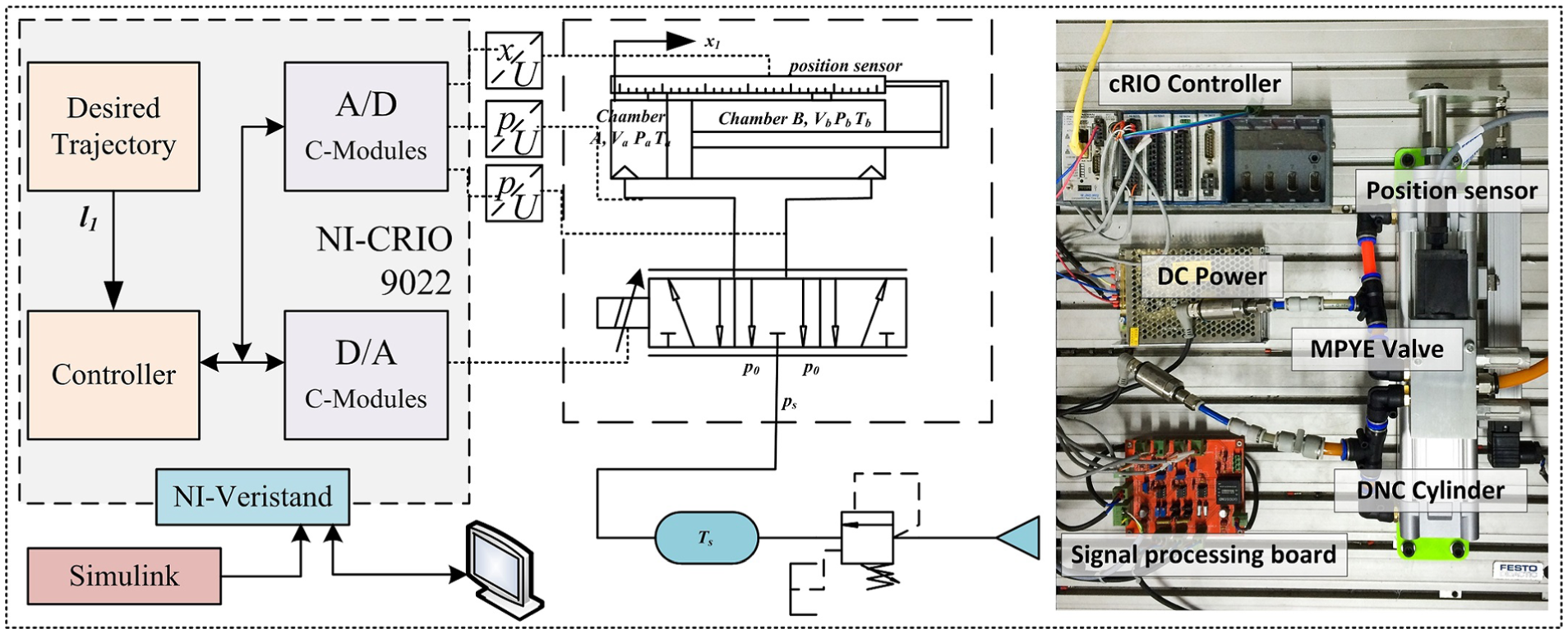
Schematic diagram and physical picture of single cylinder position control system.
Key symbols used in the model and controller.

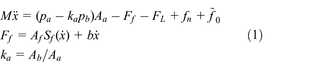
According to the coordinate established in Figure 2, equation (1) can be used to describe the piston motion and Stribeck friction model
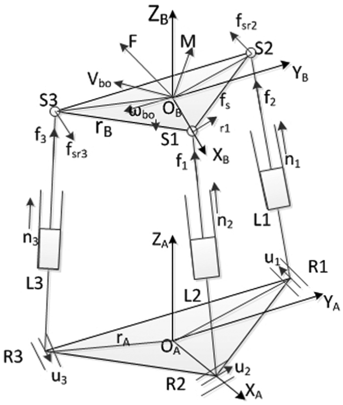
3-RPS parallel platform structure.
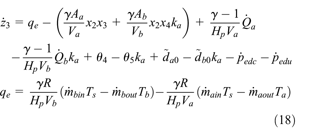
According to Carneiro and De Almeida’s 34 and Meng et al.’s 35 research results, considering the thermodynamic process in the chamber as polytropic process is more accurate
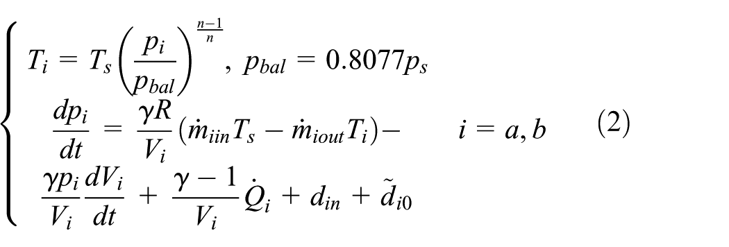
where heat exchange rate

where

The status variables vector

where
Controller design of single cylinder system
Online parameter estimation
Based on the research of online parameter estimation and back-stepping design,19,36 The adaptive law of parameters is given by

where

where
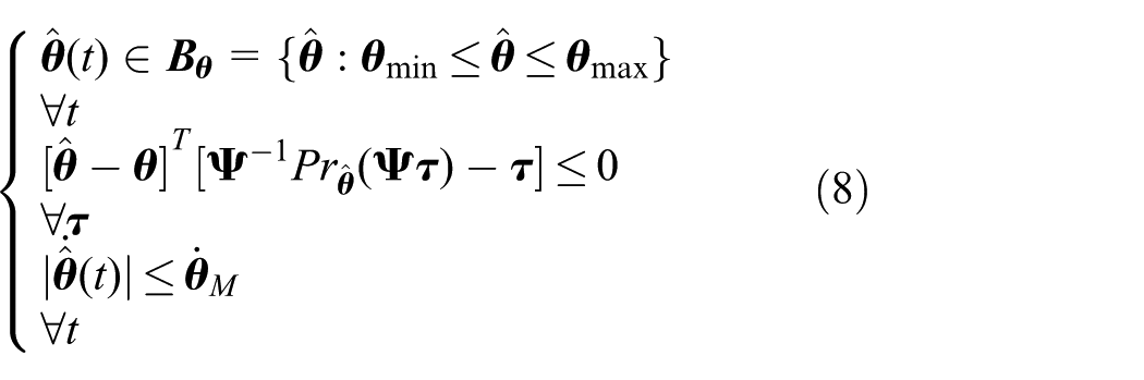
which means no matter how the adaptive function is designed, the estimated parameters vector will always be inside the known closed set
The matrix of adaptive law

where

where

where
Defining
The equation above is the standard parameter estimation model. Least square method (LSM) can be used to obtain the estimated vector
Adaptive robust controller design
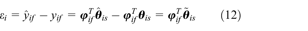
According to the system model built in equation (4), the elements of the error vector is defined as

where
To calculate the expected pressure input,
To choose property values of

To prove the stability of controller, a semi-positive definite function is defined as equation (15)

The derivation of

It is not difficult to prove that

The equations above indicate that when
where

Define another semi-positive definite function
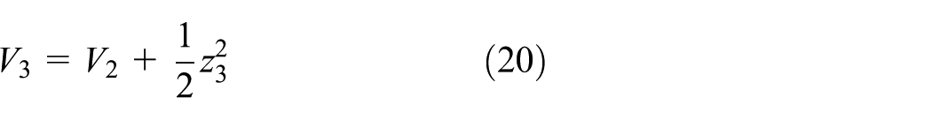
According to equation (19), it is also obvious that

Supposing
which means that the solution of
It also indicates that the upper limit of error vector

This result indicates that
After the expected mass flow

By the determination of experiment results, the relation between control voltage and valve area can be expressed as

where

Parallel system structure and analysis
Since this 3-RPS system mainly aims at the industrial market motion simulation equipment, such as in four-dimensional (4D) movie cinema, there are some guidelines to choose the proper elements: (1) to realize the ability to lift the load as heavy as two persons, considering as 200 kg, we choose FESTO DNC-63-200-P as the cylinder, which is a basic and common cylinder production; (2) to satisfy the large flow rate in the occasion of fast moving and heavy acceleration, FESTO MPYE-5-1/4-010B is chosen as the directional valve to control the piston position; and (3) one resistance position sensor and two pressure sensors are used to convert status variables to voltage values. This 3-RPS system uses NI-PXI RT system as the controller hardware, as shown in Figure 3. The control algorithm is written in MATLAB C language S-function and compiled by real-time workshop. NI provides a software named as Veristand which could link the dll model built by MATLAB and the I/O ports on PXI data acquisition cards.

3-RPS pneumatic manipulator, signal configurations, and controller structure.
According to the mechanism structure shown in Figure 2, using Tait-Bryan angles

where s stands for

where
Given the posture

where
According to the structure of the 3-RPS pneumatic platform and single cylinder servo system model, the dynamic model in joint space can be written as follows

where
The thermodynamic process in the cylinder chambers can be modeled as equation (32)

where
Figure 3 shows the basic structure of a 3-RPS pneumatic manipulator and the realistic plant. Based on the single adaptive control model estimation vectors configurations, the load parameter, which causes the biggest difference from single system to a parallel coupled system, has been considered into the online estimation. It could be inferred that the load variations caused by the parallel mechanism structure would be calculated online and the influence on the performance would be decreased. Due to the load parameters
Single cylinder control experiments
Constant values mentioned in Table 3 were used in all the models and controllers. Initial value configurations of the variables, vectors, and matrices of the controller are shown in Table 2. The experimental configuration of single cylinder is shown in Figure 1. Using NI-cRIO 9022 as real-time controller and data acquisition cards attached on it, running the controller model described above and converted by real-time workshop, the actual performance of the algorithms could be easily acquired.
Initial values for single cylinder control experiments.

The experiment results are shown in Figure 4 in the condition of 0.5 Hz sine-wave desired trajectory.

Single cylinder tracking performance with 0.5-Hz sine-wave reference trajectory. Upper panel: tracking results (red: desired curve; blue: measured curve); lower panel: tracking error results.
Figure 4 demonstrates the controller performance of a desired curve

System status: pressure in chambers (
Figure 6 gives the comparison of different control algorithms with the desired sine curve
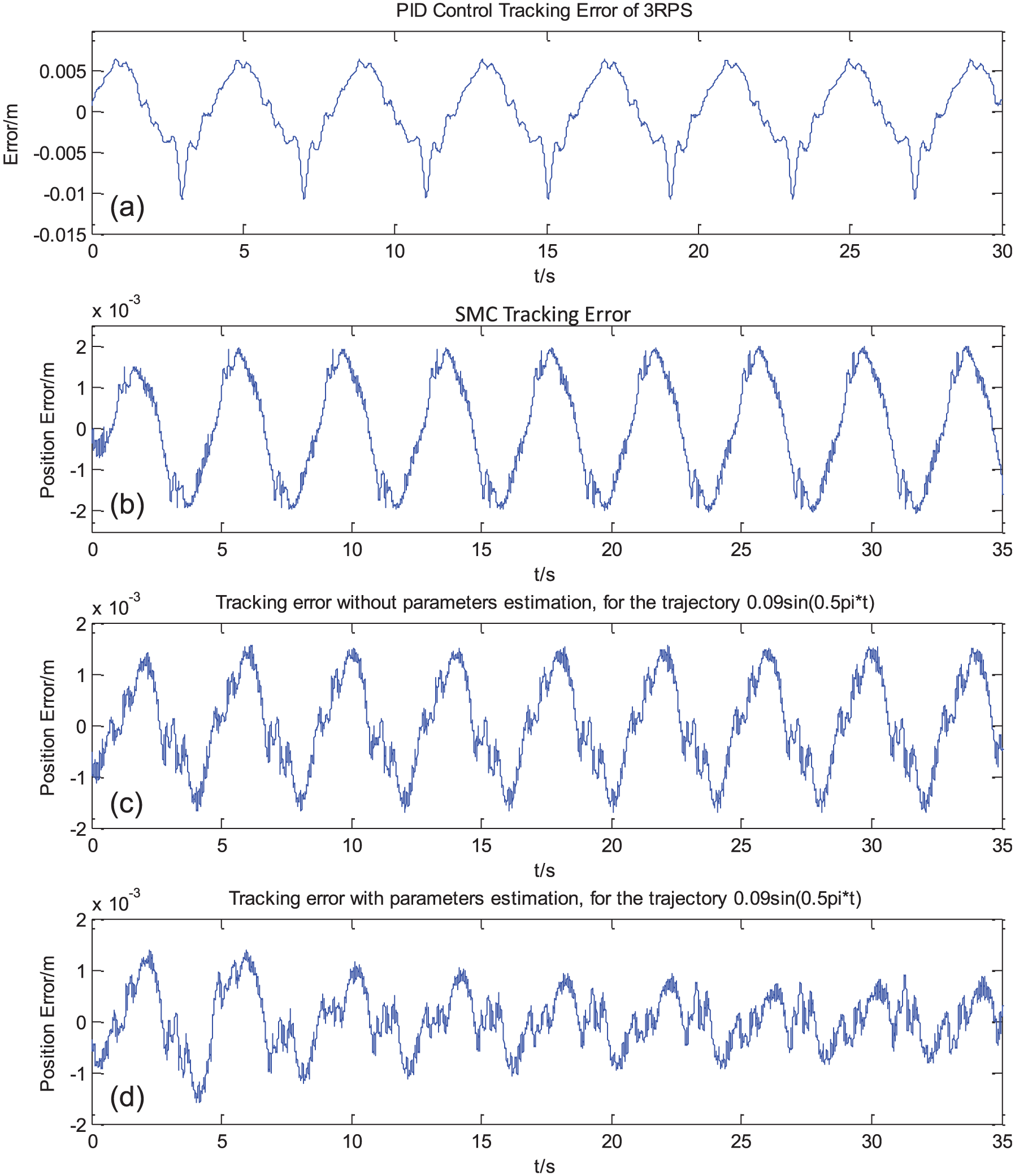
Comparison of different control algorithms: (a) PID, (b) SMC, (c) DRC, and (d) ARC. 0.25-Hz reference sine-wave trajectory.
Obviously, PID controller has the largest tracking error since the method is non-model-based, and SMC method based on back-stepping method improves the precision significantly to about 2 mm for maximum. With the adoption of robust feedback parts shown in equation (19) and online parameters estimation method, the maximum tracking error of ARC finally becomes about 1 mm.
Figure 7 demonstrates the parameters estimation result. It is clear that as the parameters converge to their actual values, the tracking performance becomes better and better, which is also shown in Figure 6(d).

Parameter estimation results of the single cylinder control, from
3-RPS manipulator posture control experiments
The scheme of 3-RPS control system and the physical equipment are shown in Figure 3. As mentioned in the former sections, the platform has 3-DOFs which are roll, pitch, and heave. Similar to the single cylinder experiment, each one’s piston position
System constant parameters used in the model and controllers.

New initial value configurations for 3-RPS manipulator posture control experiments.

For the first step of control experiment, only one of these three axes is activated while the other two are set as zero. The posture tracking results of the roll
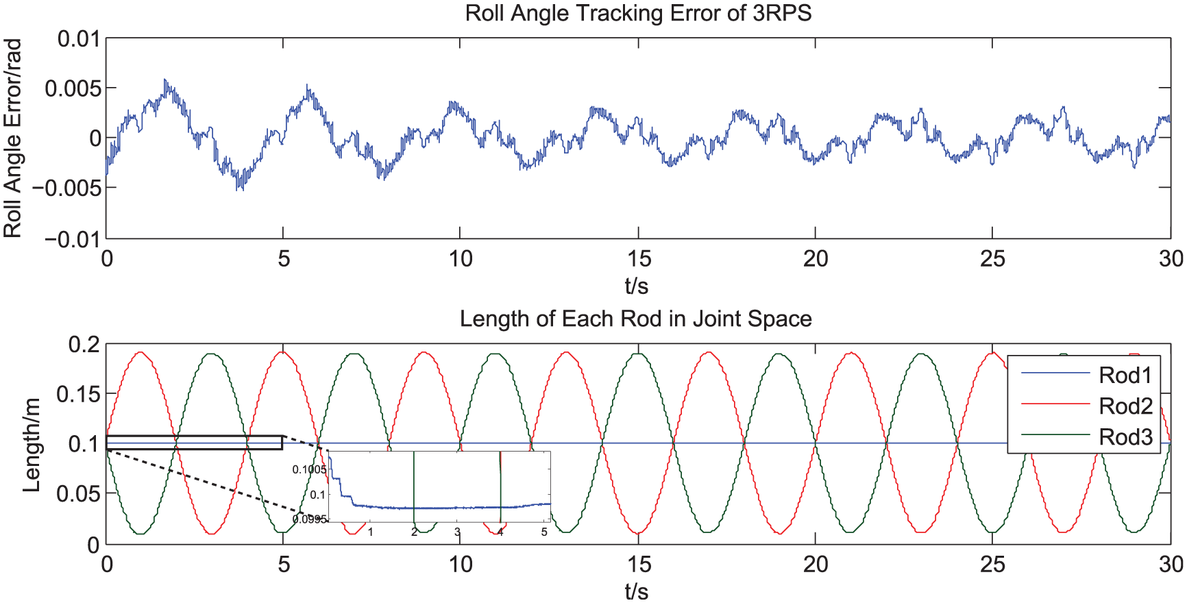
Posture tracking results, roll axis,
Furthermore, a set of compound trajectories are used as the desired trajectories in workspace. While these inputs are acting on all of the axes in workspace, that is,
Figure 9 is the result of the tracking performance of the compound trajectories. These two lines indicate that the real posture of the platform is also very close to the desired curves. The ARC control errors of three axes are shown by the solid blue lines in Figure 10. Meanwhile, the posture performance under different algorithms is also compared in this figure by the dotted red and black lines. The comparison indicated that the proposed controller improves the posture control performance of pneumatic manipulator significantly.

Compound posture reference trajectory tracking experiment result. From top to bottom, they are roll axis, pitch axis, and heave axis.

Tracking error for three dimensions in workspace under different algorithms. From top to bottom, they are roll axis, pitch axis, and heave axis. Red dotted line: SMC; black dotted line: DRC; blue solid line: ARC.
Performance analysis and conclusion
As the results shown in the figures above, the effectiveness of the adaptive robust method that used to raise the control performance for ordinary pneumatic cylinder is verified by the experiments. Based on the online parameter estimation, the tracking error becomes smaller and smaller as the estimated values converge to the actual numbers, which is shown clearly in Figures 6 and 7. Table 5 provides comparisons about the performance with different algorithms and different frequency with the proposed ARC controller for single cylinder experiments. It is clear to conclude that the method proposed in this article made a big progress on pneumatic servo control. However, there are also some uncertainties or unmodeled parts, which influence the performance more significantly as trajectory frequency becoming higher. It can also be noted that the estimation still works well in the parallel platform posture control, as shown in Figures 8–10. The precision analyses of 3-RPS manipulator are shown in Tables 6 and 7.
Single cylinder control error analysis and algorithms comparison.

PID: proportional–integral–derivative; SMC: sliding mode control; DRC: determined robust control; ARC: adaptive robust control.
Error indexes of one-axis-motion case for 3-RPS manipulator.

Error indexes of compound trajectories for 3-RPS manipulator of all axes under different control methods.

SMC: sliding mode control; DRC: determined robust control; ARC: adaptive robust control.
The maximum displacement from middle point is used here as a substitution for a compound motion curve’s amplitude.
In order to quantify the performance, error indexes are calculated by the data in last 10 s. The expressions of maximum tracking error

Overall in this study, using ARC controller proposed in this article, the precision of a 3-RPS platform driven by pneumatic cylinders was increased significantly to about 0.5%–0.7% (relative error). This controller has successfully overcome the disadvantages of the parameters uncertainty and non-linear characteristics of pneumatic system. The results of the performance satisfied the precision demand for a motion simulator used in 4D movie cinema. However, there were also some challenges to face when considering more about the real working conditions. In the experiments, the platform has not been working in the situation of fast moving and heavy load. Meanwhile, in the controller design for 3-RPS manipulator, the equivalent mass on each piston rod was considered as constant, which was varying actually. This was compensated by the robust part and parameters uncertainties estimation method. However, the online load estimation might fail to identify the actual value while the desired trajectory was changing quickly. The research on how to prevent the disadvantages brought by the large and fast load variation still needs to be done in the future. Meanwhile, an embedded controller hardware solution must be proposed to substitute NI-cRIO/PXI systems used in laboratory for an industrial production.
Footnotes
Academic Editor: Zheng Chen
Declaration of conflicting interests
The author(s) declared no potential conflicts of interest with respect to the research, authorship, and/or publication of this article.
Funding
The author(s) disclosed receipt of the following financial support for the research, authorship, and/or publication of this article: This paper is supported by National Natural Science Foundation of China (No. 51375430).