
Abstract
This work develops a process that solves the problem of the formation of cracks inside forged gas fittings in the cold forging process that arises from poor forging process design. DEFORM-3D forming software was utilized, and macroscopic experiments with optical microscopy and scanning electron microscopy were conducted to investigate the processed structures and the distribution therein of metal flow lines, and to find the internal micro-cracks to determine whether the cold forging process is reasonable. Analytical results herein demonstrate that the stress and strain inside the gas fitting can be elucidated using metal forming software. Together with experimental results, they demonstrate that a concentration of stress damages the workpiece in the forming process. Moreover, as metal flow lines become narrower, the workpiece becomes more easily damaged. Consequently, the improved cold forging process that is described in this work should be utilized to reduce the occurrence of fine cracks and defects. Planning for proper die design and production, increasing the quality of products, and reducing the number of defective products promote industrial competitiveness.
Introduction
Customers demand greater quality in this progressive era. Process problems in the forging industry are frequently solved by experienced operators on site. Repeated modifications of a component with a complex forging processes must be made to ensure that the component meets customer requirements. However, such experiences are not completely and effectively to pass on. This will induce the same problem that occurs repeatedly. Not only can the quality of a product become unstable, the increasing defect rate increases production cost and reduces profit. A computer-assisted analysis software package, DEFORM-3D, which adopts the finite element method (FEM), is utilized in industry to control the flow of deformed material in the forging process. The effective strain, effective stress, and velocity field of forging materials in the forming process can be simulated using a computer. Accordingly, poor designs can be modified to reduce the incidence of defective dies. This approach can enhance work efficiency as well as reduce research and development (R&D) and design costs.
The analysis of metal forming applications originated with Kobayashi et al. 1 in 1989, when a lot of immeasurable data were acquired and the forming details and process parameters could be discussed and traced for carefully observing the forming process. DEFORM-3D, developed by US Scientific Forming Technologies Corporation (SFTC), is currently the most widely used software for simulating and analyzing forging.2,3 In 2002, Wu and Hsu 4 utilized finite element software to analyze axially symmetric extrusion forging and they discussed the effects of mold parameters on formability. They concluded that the angle of inclination and round angle of the die do not affect forming load, while the extrusion height and extrusion width of the forging piece do. They simulated larger inclination angles and smaller round angles, and the yielded results revealed that a larger extrusion height yielded a larger extrusion width. Finally, they produced a three-dimensional (3D) contour plot of inclination angle radius, mold chamfering angle, and forming strain to identify trends in the distributions of these variables. In 2007, Kim 5 applied multi-stage continuous cold forging to form a terminal pin, using CAMPform-3D for verification, produced products with less than 10% of the number of defects that are caused by welding. In the same year, when near-net-shape forging was introduced to achieve zero waste, Lin et al. 6 utilized DEFORM-3D to analyze hex bolt forming. By simulation and trial and error, four types of near-net-shape forging to form hex bolts were developed, and a new near-net-shape forming design was proposed and simulated in DEFORM-3D to evaluate its feasibility. In 2008, Cheng et al. 7 attempted to simulate an entire forging process of a gas turbine compressor blade from a cylindrical billet to a complicated product, using 3D rigid-viscoplastic FEM. The simulation result was verified through comparisons with industrial trials and hence could be applied to other types of 3D turbine blade forging processes. Hsia 8 utilized the FEM software package DEFORM-3D to simulate 3D micro-pin forward extrusion and the forging process. They simulated the forward micro-extrusion of a workpiece and discussed the differences between the simulated process and the experimental process. The determined effective stress–strain and material flow properties after extrusion when the material was formed were used as an evaluation standard for designing a punch head and determining the designed strength of a die structure. Hsia and Shih 9 utilized finite element analysis to predict the wear of the interfaces between the workpiece and the die and the distribution of stress in die forging. The upper punch with serious wear was further evaluated to optimize the cold forming process. The authors reported a 19.87% improvement in the wear of the upper punch, and a consequent increase in die life.
Zhang et al. 10 regarded forging flow lines as fibrous structures that are formed by impurities, chemical compounds, segregation, and grain boundaries in the metal forge forming process as a form of mechanical anisotropy. In the plastic processing of a metal crystal, such as by rolling, forging, and pulling, the crystal is stretched in the longitudinal direction. The fibrous flow line structures thus produced are forging flow lines. Forging flow lines are similar to tree stripes: when forging fibers and forgings are oriented in the direction of tension, the strength and fatigue resistance of the forgings may be substantially enhanced. A reasonable metal flow line distribution allows for the full potential of the metal material that is being developed to be realized. Therefore, when forging materials are utilized to manufacture important components, metal flow lines are strictly specified. The direction of metal flow reflects the macrostructure of the forging process. When a workpiece is forged, its tensile strength or yielding point is not related to the metal flow lines, but the elongation, drawing, and impact values are strongly affected by metal flow lines.
Tseng 11 concluded that a sudden change in the geometric shape of materials can redistribute and concentrate stress. Ductile fracturing normally occurs in a material that is undergoing plastic deformation as a result of dislocations following the application of external stress. A large movement in dislocations can cause dislocations to become entangled, inhibiting subsequent dislocation movement (work hardening); the consequent dislocation pile-up generates a stress concentration (σ = GbN, where G is the shear coefficient, b is the Burgers vector, and N is the number of dislocations). A local stress concentration can cause local lattice fractures with micro-cracks that remain after the stress concentration has been eliminated. Successive applications of external stress allow the material between the micro-cracks to continue to undergo plastic deformation and necking until a complete fracture occurs, forming a characteristic dimple structure. Alexandrov and Lyamina 12 reviewed several theoretical and experimental methods for the assessment of ductile fracture criteria and for their application to the fracture prediction in the metal forming processes. A theoretical/experimental method to reveal a possible effect of geometric singularities on the applicability of ductile fracture criteria was provided in this study. Hsia and Chou 13 examined the effects of the velocity and attenuation characteristics of ultrasound on the grain size and material hardness of heat-treated C1045 middle carbon steel. They established that a smaller mean grain size and a larger hardness are obtained using higher quenching temperatures, and higher acoustic velocities and lower attenuation coefficients are obtained in materials of greater hardness.
Original and improved cold forging processes were utilized to form gas fittings and to analyze the various defects that are generated during cold forge forming process. The results demonstrate that forge damage during material forming is caused by stress concentration. In plastic forming, obvious hollows and cracks appeared on the surface when the material was plastic and the yield strength was exceeded, and thinner flow lines of forge-formed gas fitting corresponded to easier fracture. In this study, forward extrusion was applied to the improved design instead of bidirectional extrusion, to yield simple metal flow line tracks, avoiding damage to the material.
Basic theory
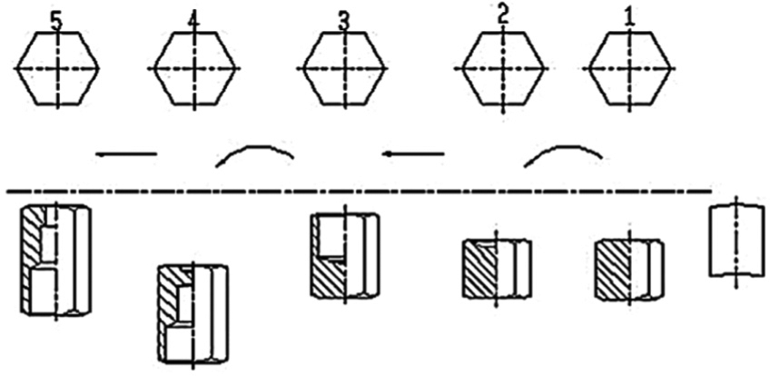
The FEM and metallographic testing were utilized to analyze the shortcomings of gas fittings that were formed by cold forging. Figure 1 displays the stages of the original process for forge forming gas fittings. In this figure, in the first stage, the top of the workpiece is trimmed to flatten its top and bottom. The second stage involves forward extrusion to form a die hole. The third stage involves backward extrusion to form a hexagon. In the fourth stage, forward and backward extrusions are carried out simultaneously, and the size of the fitting is controlled for post-processing. In the fifth stage, a through-hole is formed. Figure 2 presents the tool system that is utilized in the original stage 1; it consists of an upper punch, die, workpiece, and lower punch. When a new product is designed, the forming process in each stage must be consistent with the designer’s die design and the method of production.

Five stages of original cold forging of gas fitting and corresponding sketch maps.
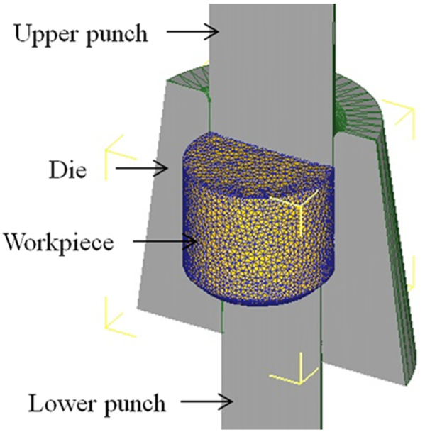
Components used in cold forging process.
A metal can be deformed by an external force in such a way that the part or whole of the metal cannot return to its original state after the external force is removed. This property is called plasticity. The remaining deformation is called plastic strain or permanent strain. Not only can an item be changed by plastic processing, the crystal structure of its material can be improved by, for example, the elimination of segregation and air pores by extrusion under a great external force. The mechanical properties of a piece can therefore be enhanced. The workpiece returns to its original state after an insufficient external force is removed, and the phenomenon is called elastic deformation. When the external force exceeds a certain value, plastic strain, or yielding, occurs. Increasing plastic deformation to a given threshold results in fracturing. The basic theories about plastic processing are explained below.
True stress and true strain
Given an initial cross-sectional area A0 and the initial height h0 of a metal, stress σ0 and strain ε0 can be calculated; their relationship is given by the engineering stress–strain curve. However, this curve does not capture the actual relationship between the stress and strain of a deformed metal and cannot represent real deformation characteristics. To eliminate this discrepancy, Ludwik proposed the idea of true stress and true strain, which satisfy the following equations


where h is its final height and p is the punch load.
Metal yield criteria
Yield criteria refer to deformation in an elastic metal under stress. Using yield criteria, metal plastic deformation under stress can be determined; however, any suggested yield criteria must be proven with experiments. Tresca yield criteria and Mises yield criteria are commonly utilized in plastic processing analyses. 14
Design size based on Tresca theory, which is conservative, is larger than when based on von Mises, which tends to be economically conservative.
In Tresca theory, only maximal and minimal stresses are required, while all major stresses are required for von Mises. Material mechanics is generally based on the maximal shear stress theory of Tresca, while machine design is referred to the distortion energy theory of von Mises.
Constant shear friction
Friction related to constant shear friction τf and shear yield strength k is called constant shear friction, defined as

where m is the friction factor or shear friction coefficient and 0 ≤ m < 1. Constant shear friction is applicable to cold/hot/warm forging with larger interfacial pressure. Sticking friction is set at m = 1.0, and the large hot forge shear stress (τf = k occurs when materials stick together) is generally assumed to be sticking friction.
Material fracture analysis
Ductile fracture
The tangling of dislocations inhibits their movement (work hardening) and concentrates stress as a result of dislocation pile-up. A local stress concentration induces local lattice fracturing, leaving micro-cracks after the stress concentration is removed. Successive external stressing allows the material between micro-cracks to continue to undergo plastic deformation and necking until it is completely fractured and shows characteristic dimpling.
Quasi-cleavage fracturing
When external stress moves dislocations and causes plastic deformation, work hardening that is caused by large movement of dislocations results in large-scale lattice fracturing, because the piling up of dislocations generates a local stress concentration. The remaining material undergoes ductile deformation until it is completely fractured when stress concentration is removed, forming the so-called rosette pattern. 15
Finite element method
Problems involving complicated geometry, loading, and material properties cannot be solved with mathematical analyses. For an unknown continuum, an analytical solution is arrived at by solving “local” mathematical equations of the object containing an infinite number of “local” stress points. FEM assumes that the unknown continuum can be divided into a finite number of “local” points called elements. An element boundary point is called a node, and each node contains a mathematical equation called an interpolation equation. The continuum is expressed by finite interpolation equations, their solutions being called interpolation approximations. When the assumptions of the continuum’s field variables (displacement, velocity, strain, stress, temperature, electromagnetic field, acoustic field, population, chemical concentration, etc.) and various other conditions (geometry, initial conditions, boundary conditions, material properties, cost limits, etc.) are correct, an approximate solution within an error tolerance can be a reliable replacement of an exact solution. Applying the FEM to analyze metal processing presents the advantages of (1) being able to acquire detailed data (e.g. velocity field, geometric shape, effective strain, effective stress, temperature change or contact pressure, and displacement distribution) after object deformation and (2) requiring little programming content and input data when analyzing several relevant problems in rapid solution environments.
Experimental equipment and procedures
AISI 1008 low carbon steel, having low carbon content and being relatively soft, was utilized in this study as it could be directly forged without spheroidizing annealing. Material strength and hardness in most metals become greater with increased processing following cold processing, reducing the material’s ductility, and making it brittle. An excessive amount of processing during forging often causes suddenly bought in metal flow line distribution, making cracks likely to appear. Focusing on gas fittings, a series of experiments and analyses were done in this study. By comparing penetrant test analysis, optical instrument measurements, and computer simulation analyses, the optimal forging process was determined. The relevant experimental equipment, procedures, and parameter settings are described in this section.
Horizontal forge forming machine
A five-stage horizontal forge forming machine (NP-45B5S5; Tong-guang Corp.) was utilized for backward and forward processing movements in the slider-crank mechanism and linkage transmission.
Cylindrical compression test
For more accurate simulation results, the cylindrical compression test (Figure 3) was used for acquiring the true-stress–true-strain curve for use in the finite element software DEFORM-3D to simulate the gas fitting process. The equations used on the cylindrical compression test are demonstrated as (1)–(5). The equation
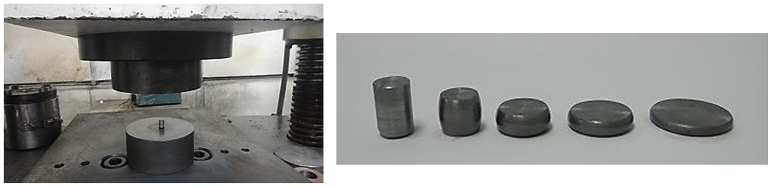
Compression test and compressed cylindrical samples at different reductions.

True-stress and true-strain curve of AISI 1008 (hi is the initial height of the compressed cylindrical sample and di is the diameter).
Observation of metallographic structure
Metallographic analyses of specimens in the fourth stage were observed under an optical microscope (OM).
Use a grinding machine for grinding the samples with 320#–2500# aluminum oxide sandpaper, and a polishing machine was also utilized for polishing with diamond suspension till no scratch left.
Etch with 3% nitric acid etching solution for 10 s.
Clean the etching solution on the samples with water and blow-dry the samples.
The etched samples were proceeded metallographic examination with an OM.
The amplification factor 200× was used for observing the metallographic structure and taking pictures of the test piece.
DEFORM simulation setting
Simple formation rather than thermal conduction was the basis for the pre-processing settings used in DEFORM simulations. In the forming process, all die parts except the workpiece were set as rigid bodies and the cold forge forming temperature set at 20°C. Also, according to the convergence analysis, 35,000 mesh numbers could get a better accuracy results and save unnecessary simulation time. The relevant analysis settings are shown in Table 1.
Simulation parameters in DEFORM.

Results and discussion
The FEM and metallographic testing were utilized to identify the shortcomings of the gas fittings that were fabricated using the original and improved cold forging processes. The waste is punched out after the punch top comes into contact with the workpiece, and the punch size in the fifth stage is the final size of the formed product. Accordingly, only the following four stages of the original cold forging process were analyzed.
Original first stage
Preforming was carried out to establish the workpiece and chamfer the die bottom to remove cuttings. The unevenness of the workpiece surface, caused by cutting of the material, induced die bottom burst. The long-term extrusion of sharp edges affects die life and sometimes produces surface defects on the product. In the simulation, at the start of forging, the upper punch moved downward toward the die or the after-punch; the die and the after-punch were fixed at this stage.
The wire was cut using scissors or shears before forging, and the workpiece was delivered to the first die with a clamp for first-stage preforming. Figure 5 presents the load that was born by the upper punch in the four stages. The load slowly increased initially until the forging load of the upper punch reached 510.37 kN at a stroke of 2.60 mm in Step 26 in Figure 6. The workpiece at this time met the setup preforming criteria, and the load on the upper punch increased with each step until the workpiece almost completely filled the die and ceased to flow easily. The load, therefore, increased rapidly and the die was easily fractured, affecting service life. Figure 6 displays the analytical results for the first stage. The maximal effective stress was at the contact between the workpiece head and the die bottom in Step 26, and the position of maximal effective strain was that of maximal effective stress, where die fracture was most likely to occur. The maximal principal stress appeared on the upper punch edge and the die aperture was maximal near the lower punch (Figure 6(c)).

Forging load versus stroke in each original stage.

Simulated outcome of the original first stage in 3D: (a) effective stress, (b) effective strain, and (c) principal stress.
Original second stage
The workpiece that was formed in the first stage was delivered to the clamp in the second stage. The upper punch head in the second stage was first used to make a hole in the workpiece, which would become the punch extrusion hole in the following stage. To prevent the formation of a large concentricity offset between the inner hole and the outside diameter of the workpiece in the following stage, forward extrusion was carried out to form a back hole.
The workpiece that was obtained in the first stage was delivered to the second state with a clamp and pushed into the die with the upper punch. In Step 138, in which the workpiece had reached the required preforming hole depth, the load that was born by the upper punch during forge stamping (Figure 5) was 678.01 kN at a stroke of 11.1 mm. SKH55, with a hardness of HRC63∼65, is normally used to fabricate the upper punch and the lower punch. The highest effective stress and effective strain in this stage are present in the lower punch top, where the die bears the largest pressure and is easily worn (Figure 7). Powdered high-speed steel ASP30 with a higher hardness, HRC65-67, is normally used, and the tool surface is treated with titanium plating (TIN). Figure 7(c) displays the distribution of maximal principal stress. A larger compressive principal stress appears when the lower punch precedes forward extrusion, and tensile stress occurs at the die wall.
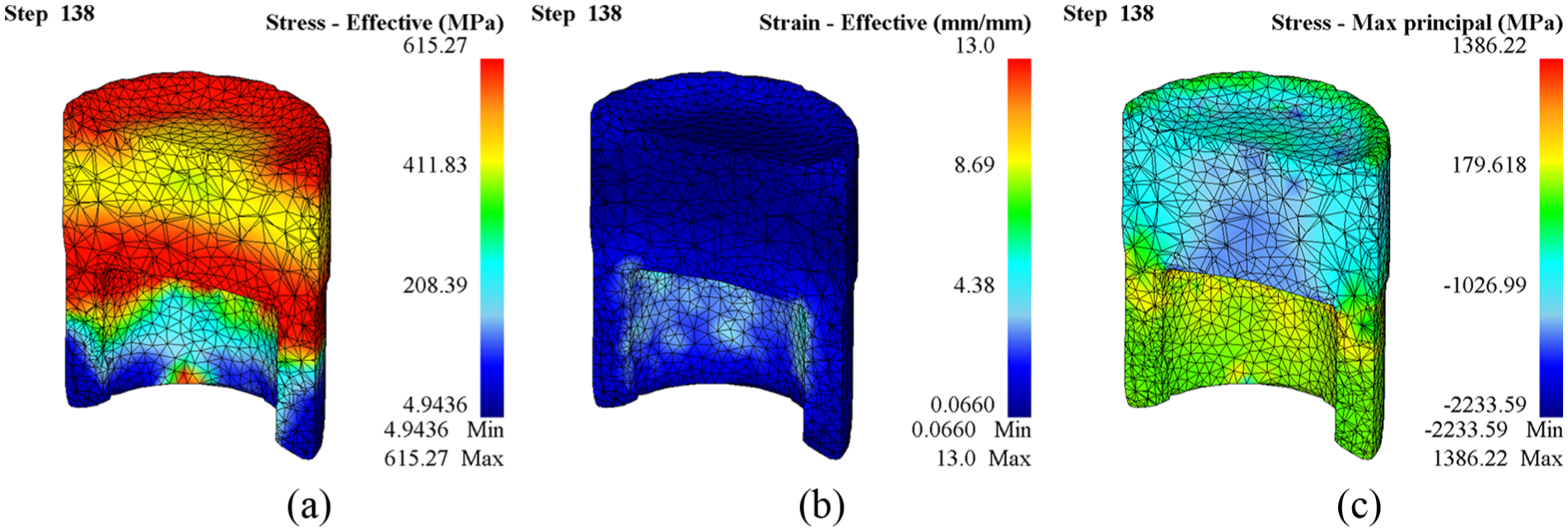
Simulated outcome of original second stage in 3D: (a) effective stress, (b) effective strain, and (c) principal stress.
Original third stage
The workpiece that is formed in the second stage is delivered to the third stage with a clamp. The workpiece now has a hole that is utilized in backward extrusion in the third stage punch to optimize the concentricity of hole and gas fitting.
Figure 5 plots the load that was born by the upper punch in the third stage, forge stamping. At Step 242, in which the hole in the workpiece reached the preforming specifications for the stage, the forging load on the upper punch was 871.00 kN at a stroke of 10.4 mm. The effective stress in this stage was greatest on the top of the third upper punch, because the workpiece was extruded backward with sufficient flow that the tool was not seriously worn (Figure 8). The area of maximum effective strain was on the forming-hole wall of the workpiece, where deformation was increased by backward extrusion. At the same time, the compressive principal stresses at the top of the upper punch were large, because metal flow within the workpiece was difficult (Figure 8(c)).

Simulated outcome of original third stage in 3D: (a) effective stress, (b) effective strain, and (c) principal stress.
Original fourth stage
The original fourth stage involved composite extrusion for forming. The workpiece in the third stage was delivered to the fourth die using a clamp. The upper punch and the lower punch underwent composite extrusion with the expectation that the workpiece would reach its proper size in this stage. Forging cracks were frequently generated by the bidirectional flow of the workpiece in this stage.
When the material was extruded backward by the upper punch, the punch was covered with the workpiece after forming, due to friction and spring-back when the die kernel was removed. The workpiece, therefore, left the die with the upper punch rather than being clamped to the following die. The new workpiece and the previously formed workpiece that were attached to the upper punch were then moved into the same die, causing die crash in the next forging cycle and consequent die fracture. Applying an ejecting mechanism to the die system secures the workpiece and prevents die crash.
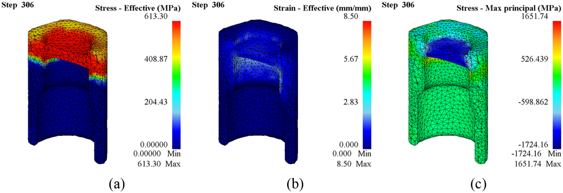
Figure 5 shows the load that was born by the upper punch during forge stamping in the fourth stage in the simulation. At Step 450, the forging load on the upper punch was 180.57 kN at a stroke of 6 mm, and the specified hole depth was achieved. Composite extrusion was conducted in this stage. The material did not flow at the final area of the upper punch and lower punch drawing stroke, because the value of the velocity field in the dead area was large and metal flow was bidirectional. Accordingly, the effective stress, effective strain, and maximum principal stress were highest close to this area (Figure 9). Because of the fast flow velocity and dense pattern of the material in this stage, designers should carefully consider the above situations to avoid the formation of cracks in the forging process.

Simulated outcome of the original fourth stage in 3D: (a) effective stress, (b) effective strain, and (c) principal stress.
The fractures that occurred during the forming of gas fittings before improvement revealed fibers that were caused by the expansion of cracks, associated with plastic deformation. Such fractures reveal ductile failure. Quasi-cleavage failure of the specimen was observed under a scanning electron microscope (SEM, HITACHI S-3000N) in the fourth stage (Figure 10). With etching, obvious and dramatic changes of metal flow lines were found (Figure 11). Metallographic analyses of etched specimens in the fourth stage revealed obvious fractures and shear bands that were oriented 45° from the axis, as observed under an OM (OLYMPUS BX51M). The fractures were similar with the situation of maximum shear stresses (Figure 12). When the erosion time was extended to 30 s, the grains were large and unidentified objects were observed. Such abnormal metallographic items were identified as carbide within the material; the black spots were non-metallic foreign materials (Figure 13), and the flow line tracks were obvious.

Characteristic quasi-cleavage fracture.
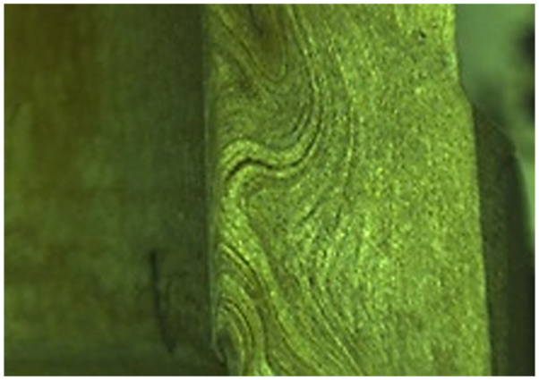
Metal flow lines on the final product that was based on the original design.
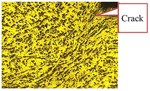
Crack induced in the original fourth stage.
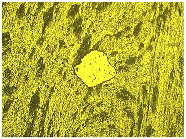
Etched product of original cold forging (×200).
The original cold forging process produced forging fractures by the formation of stress concentrations in the forming of gas fittings. In the forge forming process, the material surface exhibits obvious collapses and cracks if it is over-processed beyond its yield strength, and a denser flow line distribution more easily results in material fracture. Consequently, forward extrusion was a better method than bidirectional extrusion, because it simplified metal flow lines and prevented fracture of the material. Therefore, the first to fourth stages of the new and improved cold forging process (Figure 14) were analyzed as follows.
Five stages of the improved cold forging process for forming gas fittings and corresponding sketch maps.
Improved first stage
Improved preforming was performed in the first stage, mainly to establish the workpiece and the die bottom chamfer so that the workpiece would easily flow in the second stage for die life enhancement. The workpiece was modified from round to hexagonal for easier flow and smaller loading, resulting in better die life. According to experience, the die bottom chamfer was easily worn. When forging began, the upper punch moved downward toward the die or lower punch while the die and the lower punch were fixed. When forging started, the material was cut with a shear or a cut-off knife and the workpiece delivered by a clamp to the first die for preforming setup. In Step 40, maximum effective stress and maximum effective strain appeared at the same position (Figure 15(a) and (b)). The maximum principal stress was the compressive stress between upper punch and lower punch and concentrated on the top of the punch heads, where the workpiece directly contacted. At the same time, the tensile stress was contained when close to the die wall (Figure 15(c)). In general, the maximum flow velocity of the workpiece appeared on the die bottom where the lower punch entered and where chipping easily happened in the tungsten die core. This was also where the transition occurred for tension and compression during principal stresses, and sometimes the constrained material acquired defects on the product surface.
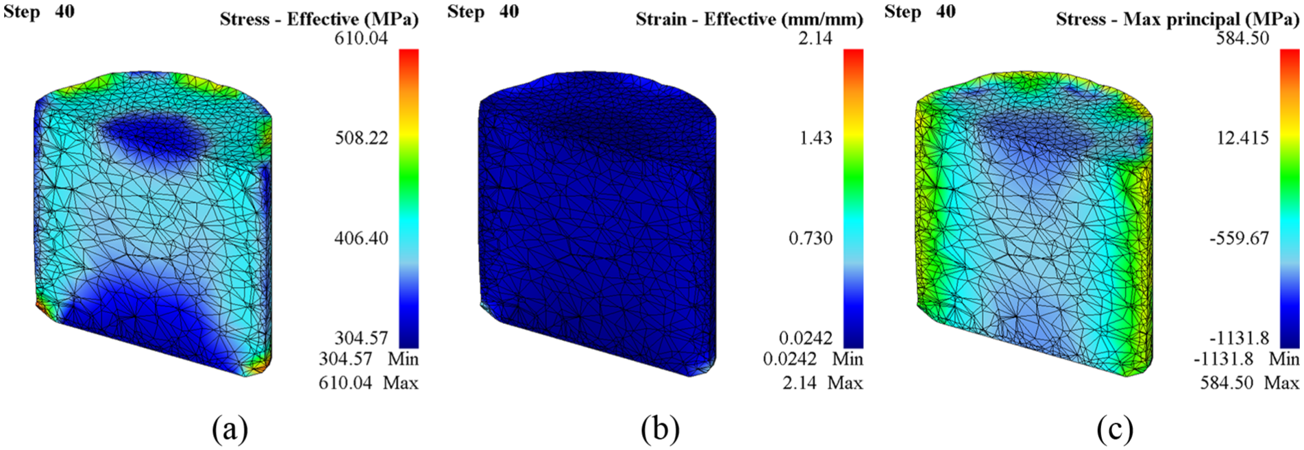
Simulated outcome of the improved first stage in 3D: (a) effective stress, (b) effective strain, and (c) principal stress.
Improved second stage
In the improved second stage, the first stage workpiece was turned and delivered by a clamp into the second die and then the workpiece extruded into the die with the punch. The maximum effective stress and effective strain at the improved second stage were concentrated on the upper punch head and the forming die bottom chamfer (Figure 16(a) and (b)). The maximum compressive principal stress was concentrated on the upper punch head and die bottom chamfer, while maximum tensile principal stress was distributed around the die wall (Figure 16(c)).

Simulated outcome of the improved second stage in 3D: (a) effective stress, (b) effective strain, and (c) principal stress.
Improved third stage
The workpiece from the second stage was used to simulate the third stage. It was delivered to the third die with a clamp and pushed into the third die with an extrusion punch. The maximum effective stress at the third stage was concentrated on the hole bottom (Figure 17(a)) and the maximum effective strain appeared on the pilot hole wall of the upper punch (Figure 17(b)). The maximum compressive principal stress was concentrated on the upper punch head and die bottom chamfer, while maximum tensile principal stress was distributed around the center of the workpiece (Figure 17(c)).

Simulated outcome of the improved third stage in 3D: (a) effective stress, (b) effective strain, and (c) principal stress.
Improved fourth stage
The workpiece acquired at the third stage was used to simulate the fourth stage. After the workpiece entered the fourth die, the upper punch pushed it fully inside the die for extrusion. The maximum effective stress at the fourth stage was concentrated on the hole bottom (Figure 18(a)), and the maximum effective strain appeared in the direction of the punch extrusion (Figure 18(b)). The maximum tensile principal stress was expressed throughout the workpiece due to forward extrusion except for the upper punch end bearing the compressive principal stress. The workpiece was able to flow completely into the die because of the change in maximum tensile principal stress that improved die life. This one-way extrusion design did not result in forging cracks (Figure 18(c)).
Simulated outcome of the improved fourth stage in 3D: (a) effective stress, (b) effective strain, and (c) principal stress.
This section analyzes the forging load from the first stage to the fourth stage, as displayed in Figure 19. In the preforming of the workpiece in the first stage, the process approached closed forging in which the forging load was 582.73 kN, approximately 23.93% of the total punch loads in the four stages. In forming in the second stage, the forging load was 479.02 kN approximately 19.67%, which is clearly less than in the other stages. In inner hole forming with closed-die upsetting in the third stage, the forging load, 802.77 kN approximately 32.97%, was larger than in any other stage. In the fourth stage, the forging load, 570.70 kN approximately 23.44%, was the second smallest of any of the loads in the four stages. Overall, the total forging load for forming gas fittings from the first stage to the fourth stage was 2435.22 kN.
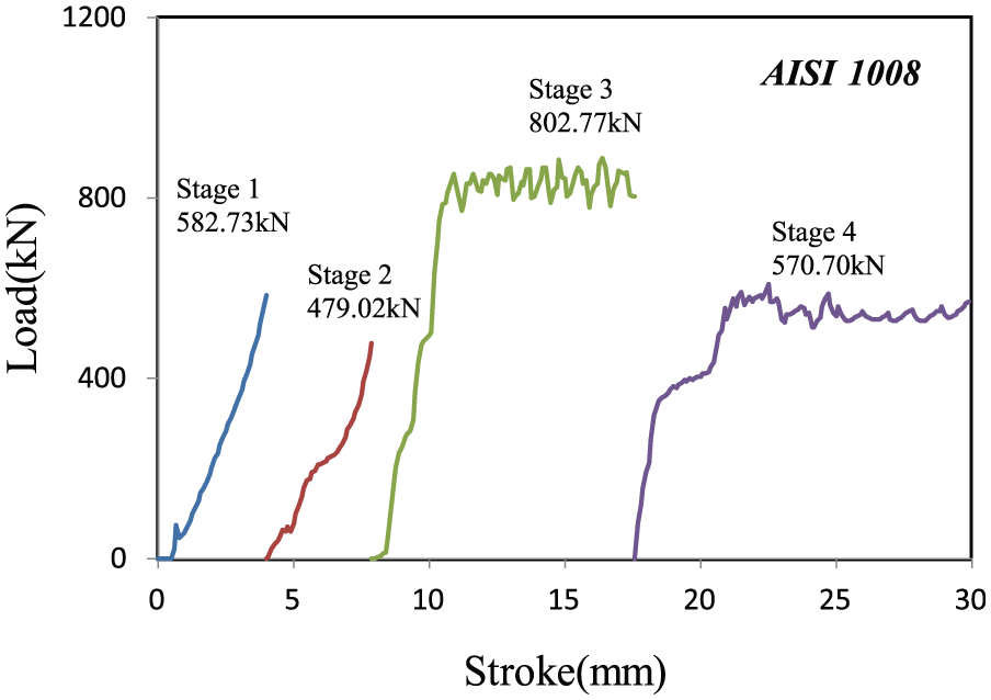
Forging load versus stroke in each improved stage.
In this improved cold forging process, the use of forward extrusion instead of bidirectional extrusion simplified metal flow lines and prevented fracture of the material. Figure 20 presents the results of penetrant testing of the original and improved products. Cracks were observed on the inner surface of the original product. The OM image in Figure 21 reveals smooth metal flow lines at the corner of the formed gas fitting, so no crack was detected in the penetrant test, as displayed on the right-hand side of Figure 20. In the penetrant testing, five different test products of the improved cold forging process were utilized, and the failure products formed by original cold forging process were returned from the customers when utilized in very cold weather.
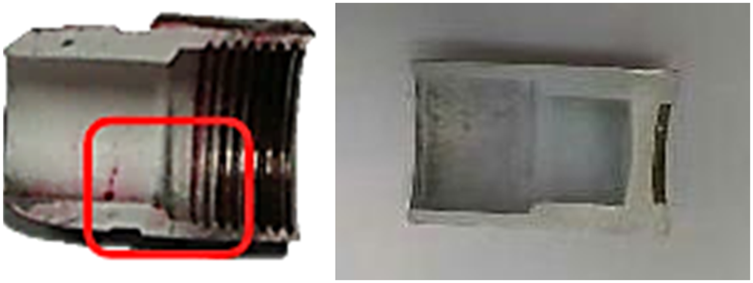
Penetrant testing of original (left) and improved (right) cold forging products (cracks are observed in the red box).

Metal flow lines on the final product that was formed using the improved forging process (×50).
Conclusion
In this work, metallographic testing was performed to optimize the forming method and DEFORM-3D was used to simulate consequent improvement of the cold forging process for gas fittings. The following conclusions are drawn concerning cracks in the material that is formed in the cold forging process:
Finite element simulation and experiments on the original process prove that dense metal flow lines resulted in obvious cracks in the material that is used in the cold forging process. Bidirectional extrusion should be avoided in the pilot hole forming process, as one-way extrusion, such as forward extrusion or backward extrusion, is better.
Metallographic analysis of the product of the original process revealed both foreign material black spots along the metal flow lines and failure cracks that were 45° off vertical axis, and apparently were responsible for shear stress failure.
The load, effective stress, effective strain, and principal stress in various stages were obtained by DEFORM-3D finite element analysis.
DEFORM-3D simulation revealed that the effective stress and effective strain were greatest at the corner of the bottom of the die. The processing design in that area therefore determined the service life of the die.
In the improved cold forging process, the workpiece was affected by forward extrusion, so the maximum tensile principal stresses were caused throughout the workpiece, causing the workpiece to flow completely into the die. This new forming method involves one-way extrusion that does not produce forging cracks.
Footnotes
Acknowledgements
Ted Knoy and Buford Pruitt, Jr are appreciated for their editorial assistance.
Academic Editor: Stephen D Prior
Declaration of conflicting interests
The author(s) declared no potential conflicts of interest with respect to the research, authorship, and/or publication of this article.
Funding
The author(s) declared the following potential conflicts of interest with respect to the research, authorship, and/or publication of this article: The authors would like to thank the Ministry of Science and Technology of the Republic of China, Taiwan, for financially supporting this research under Contract No. MOST 104-2622-E-244-002-CC3.