
Abstract
Sculptured surfaces have been widely used in various engineering applications. With the development of five-axis machining technology, five-axis machine tool has played a more and more important role in manufacturing sculptured surfaces. This article proposed a complete five-axis machining process planning for vehicle rear bumper mold. First, a numerical model considering tool inclination was developed to predict topography and surface roughness in ball-end milling processes. And then experimental verification was conducted. Second, according to the simulation results, it can be concluded that surface roughness decreases significantly with the tilt angle increasing from 0° to 5°. When the tilt angle is 10°, surface roughness gets the smallest value. What is more, surface roughness increases slightly from 10° to 30°. In the case of the permitted surface roughness, larger feed rate per tooth and the radial cutting depth can be chosen. Finally, a process strategy was made through the analysis of the mold in which the parameters were chosen according to the simulation results above.
Introduction
In the field of free-form machining, computer-aided manufacturing (CAM) software offers various machining strategies depending on the geometry of the surface to be machined. The surface quality depends on process parameters (lead angle, tilt angle, feed per tooth, cutting speed, radial depth of cut, cutting depth) and the choice of the machining strategy. The resulting machining time, productivity, and geometrical surface quality directly depend on these parameters.
Cutting process parameters’ optimization
Wang et al. 1 and Zhang and Li 2 studied the control and optimization of cutting process and predicted the machining performance. As surface quality is concerned, the scallop generation mechanism must be well controlled. Erkorkmaz et al. 3 presented a new strategy for planning tool trajectories of minimum time in three-axis milling. Process constraint and feed drive control system limitation were both considered. Sun et al. 4 developed a more comprehensive feed optimization method with the constraints of geometry error and dynamics. Vickers and Quan 5 expressed the path-interval scallop height as a function of the curvatures of surfaces and path intervals. Kruth and Klewais 6 took the inclination effect of the cutting axis into the path-interval scallop height model. Due to limitation of cutter material, the tooth feed is kept to comparably less than the path pick, and the previous works only considered the path-interval scallop. In today’s high-speed hard machining technology, however, the tooth feed has been raised to the same level of the path pick. Chen et al.7,8 investigated the scallop height in which the effects of inclination angles were taken into consideration. The researches were conducted by geometrical analysis and experimental methods.
The simulation method is more explicit and simple compared with the geometrical analysis and experimental methods. Chen et al. 9 studied the generating mechanism of feed and path-interval scallops and the influence of process parameter on surface scallop. However, the model was only constructed with a ball-end cutter with two straight flutes. Quinsat et al. 10 developed the calculation model of surface topography characterization parameter taking the feed and path-interval scallops into account. Some research11,12 dealt with the prediction of the three-dimensional (3D) surface topography obtained in five-axis milling with an end milling cutter. However, the researchers only considered the inclination angle while ignoring the feed rate per tooth and the path interval.
In five-axis machining, more machining strategies are developed for the complex part. It makes the machining process more efficient, and it also brings more machining mistakes such as air travel, overcut, or undercut of the manufacturing. Moreover, as the tool axis orientation generally varies during machining, the resulting surface pattern can be affected. 13 The prediction of the 3D surface topography according to the machining conditions is also an important issue to achieve process planning correctly.
The machining strategy
At present, interactive graphical programming system has been widely used in five-axis milling; CAM systems provide access to a large variety of data such as the programmed feed rate, the tool length, and the number of flutes. 14 There are still problems such as collision and interference of tool path. Balasubramaniam et al. 15 presented a series of algorithms and heuristics for generating collision-free five-axis computer numerical control (CNC) finishing tool paths automatically. However, the algorithms were tedious. Jun et al. 16 proposed a searching method in the machining configuration space (C-space) to find the optimal tool orientation. It took the local gouging, rear gouging, and global tool collision into account. Zhu et al. 17 researched the high-speed milling (HSM) of vehicle front bumper die based on Unigraphics (UG) CAM. Fan et al. 18 developed methods for cutter orientation and tool path generation in five-axis sculptured surface machining without gouging. The famous iso-scallop tool paths’ generation strategy was first proposed by Suresh and Yang. 19 Ahmet and Ali 20 developed a novel iso-scallop tool path generation strategy for the efficient five-axis machining. And the cutter paths were scheduled to make the scallop height formed between two adjacent machining paths constant. Moreover, this study also achieved a maximized material removal rate by an optimized tool orientation and curvature matching. Since the iso-scallop and roughness often conflict with each other in the existing iso-scallop path planning methods, Zou et al. 21 proposed a new framework to plan globally optimal tool path. It views a family of iso-level curves of a scalar function defined over the surface as tool path so that the desired tool path can be generated by finding the function that minimizes certain energy functional and different objectives can be considered simultaneously.
Despite the progress, many challenges still need to be further addressed to improve the quality and efficiency of the specific surface machining process planning in industry.
From the literature review, it can be concluded that the current researches were mainly focused on process parameters’ optimization and tool path planning algorithms. For the cutting parameters’ selection, the surface topography at the five-axis machining is particularly sensitive to the tooth feed, the radial cutting depth, and tool axis inclination in the ball-end milling operation. However, there is still a lack of a model to clearly explain the surface scallop generating mechanism for these parameters. Since the lead angle is studied completely, the tilt angle is needed to be studied with deeper insight. As for the tool path planning, few researches were conducted for mold or other specific complex parts.
In this article, parameters’ optimization and tool path planning for specific part rear bumper mold were conducted. A theoretical model of the surface topography formation in five-axis ball-end milling was presented. The simulation and experimental verification of the model is conducted with tilt angle, feed rate per tooth and radial cutting depth being studied. And then the tool path planning for rear bumper mold based on NX9.0 was proposed. Besides, the cutting parameters were selected according to parameters’ optimization above.
Modeling and controlling of surface topography in ball-end milling
In this article, a theoretical approach is proposed to predict the surface topography obtained in five-axis milling with a filleted-ball-end cutter. Selection of the cutting parameters and their effects on the mold quality are discussed. Meanwhile, the experiment is conducted to validate the model.
Modeling
The machined surface topography is essentially generated by the motion of the cutter edge. So the cutting motion model can be described as equation (1)

where (x, y, z) is the coordinate of sweeping points’ cloud generated by cutter motion based on workpiece coordinate system.

β1 and β2 are the corresponding angles of the machine tool principal axis rotation angle. It is always used in matrix transforming since it is convenient and explicit. In five-axis milling, surface topology is affected by lead angle and tilt angle which are not equal to β1 and β2. Lead angle is the included angle between tool axis and z1-axis in Plane y1z1 which is rotated around the y-axis. In addition, y-axis is the feed direction. Tilt angle is the included angle between Plane y1z1 and Plane yz. In Figure 1, supposing the coordinate of


Cutting tool inclination angle.


(u, v, w) is the coordinate of point P (shown in Figure 2) which is on cutter edge based on the tool kinematic coordinate system. As shown in equation (8), α is the included angle between OTP and W-axis. γ is the helix angle of the tool


Tool coordinate.
The workpiece used in this article is the flat surface. And it was divided into (m − 1) × (n − 1) matrix grid (m × n grid points), as shown in Figure 3. The grid points were first valued and H represents the scallop of the workpiece in

Workpiece model.

Flow chart of surface topology modeling.
The simulation result is obtained in MATLAB software, as shown in Figure 5. Apart from the simulated surface topology, the surface roughness Ra is also simulated as shown in equation (9). In equation (9), h represents the arbitrary scallop of the point in surface topology,


Description of surface scallops in ball-end milling.
Experiment validation
A series of experiments were conducted with machining center DMU-70V (shown in Figure 6) under the process parameters as shown in Table 1. The workpiece material is P20 steel, size of 250 × 150 × 50 mm. The machined area was 50 × 50 mm. Each block allowed performing eight different experiments. The cutting tool used in this experiment is a ball-end cutter JH970100-TRIBON. The surface topography is measured by optical profilometer Wyko NT9300.

Experiments of five-axis milling.
Process parameters with same cutting speed 157 mm/s, cutting depth 0.2 mm, and lead angle 0°.

The experimental and simulated surface topographies are compared in Figure 7. The simulated results remarkably agree with the experimental results. The model is ideal in the geometrical simulation in which some physical factors were not taken into consideration, such as material plasticity, vibrations, and tool flexion.
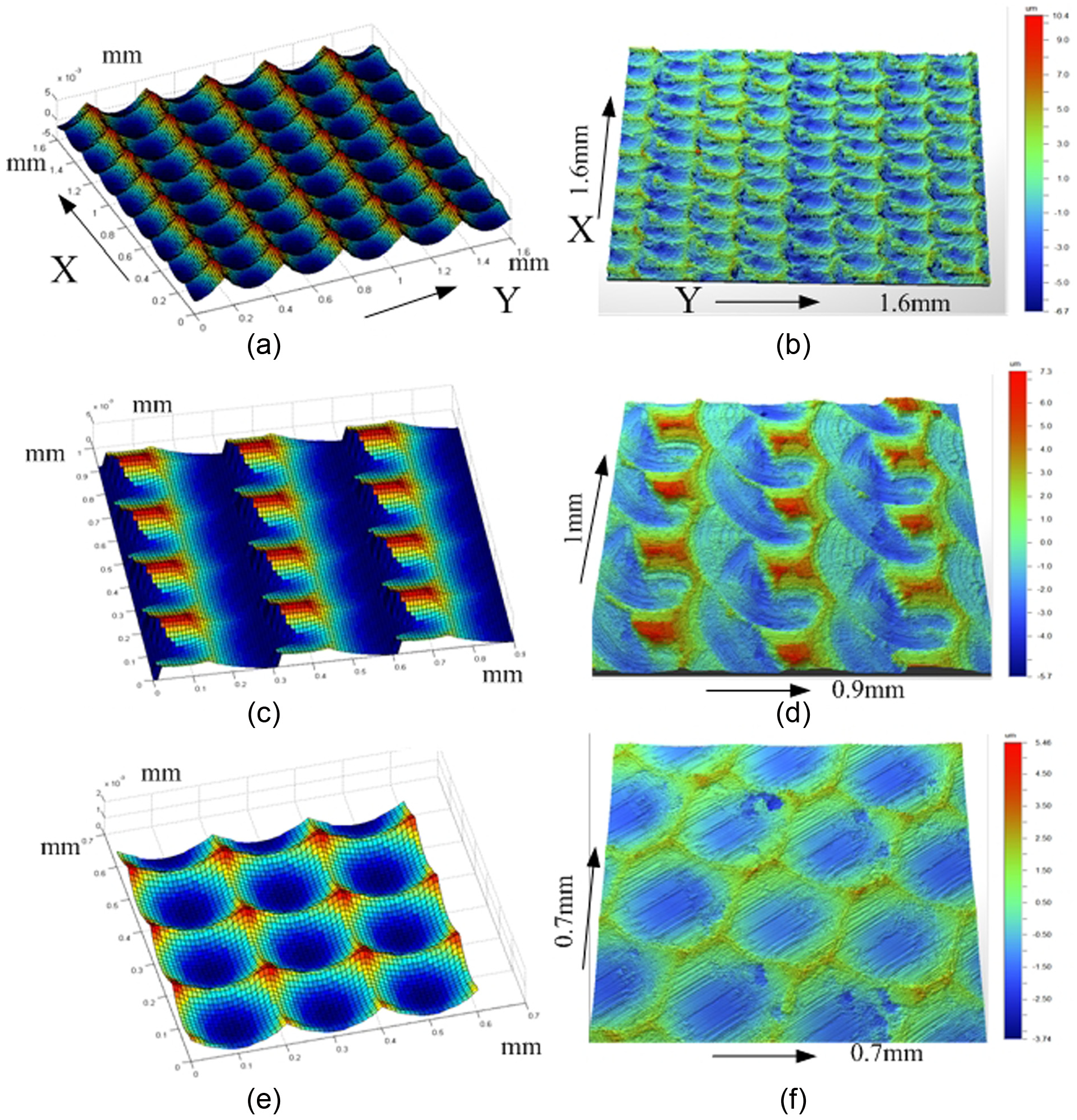
Simulation and experimental results of surface topology: (a) fz = 0.2 mm/z, ae = 0.3 mm, tilt angle = 15°; (b) fz = 0.2 mm/z, ae = 0.3 mm, tilt angle = 15°; (c) fz = 0.2 mm/z, ae = 0.3 mm, tilt angle = 0°; (d) fz = 0.2 mm/z, ae = 0.3 mm, tilt angle = 0°; (e) fz = 0.2 mm/z, ae = 0.2 mm, tilt angle = 5°; and (f) fz = 0.2 mm/z, ae = 0.2 mm, tilt angle = 5°.
Simulation results
From the analysis of the surface roughness in Table 5, it can be concluded that the surface roughness is particularly sensitive to the feed rate per tooth and radial cutting depth. With the increase in the feed rate per tooth, the surface roughness gets larger. Meanwhile, the radial cutting depth has similar influence on the surface roughness. The experiment results indicate the same tendency, but the experiment results are larger than the simulation results. This is because some physical factors such as tool vibration and material plasticity, which were ignored in the simulation also have some effects on surface roughness. Under the premise of permitted surface roughness, we can choose large feed rate per tooth and radial cutting depth.
Moreover, the surface topography is also affected by the inclination of tool axis in the ball-end milling operation. The tool inclination is divided into lead angle and tilt angle. Generally speaking, lead angle is along the feed direction and tilt angle is perpendicular to the feed direction. And the research about lead angle is intensive. However, research about tilt angle is not deep going. Figure 8 shows the effect of the tilt angle on surface roughness. When the tilt angle is 0, the surface roughness is large. This is because the velocity of the ball-end top is 0, and material plasticity and material tear lead to serious surface defect. It can be indicated from Figure 6 that the surface roughness decreases significantly with the tilt angle increasing from 0° to 5°. When the tilt angle is 10°, surface roughness gets the smallest value. What is more, surface roughness increases slightly from 10° to 30°. In other words, the tilt angle can be chosen correspondingly from 5° to 30°. Generally, in order to get a good surface quality, we can choose the best tilt angle 10°. Meanwhile, a certain tilt angle from 5° to 30° can be chosen to satisfy the actual machining process. Meanwhile, the conclusion can be used in the NC programming.

Simulation and experimental results of surface roughness.
In a conclusion, when other processing parameters are identified, the major factors influencing the surface topography are feed rate per tooth (fz) and radial cutting depth (ae). In addition, the surface roughness is also affected by lead angle and tilt angle.
The rear bumper mold process planning
Machining strategy
The 3D models of rear bumper and rear bumper mold are shown in Figure 9. The workpiece material was P20 steel, which is widely used for plastic mold, extrusion, and hot forging.

3D models of (a) the rear bumper and (b) the rear bumper mold.
The nominal chemical composition and the material properties of P20 steel are given in Tables 2 and 3, respectively. The workpiece material was hardened and tempered to attain a hardness of 30–36 HRc. A 2370 mm × 1130 mm × 1070 mm rectangular block was used as the sample.
Nominal chemical composition of P20 tool steel (wt%).

Material properties of P20 steel at room temperature.

According to the complicated cavity structure, process strategies were summarized as follows:
The mold cavity is very complicated since it has a lot of bulges and grooves. Besides, the machining allowance for steel is not well-distributed. Scrape will appear due to the harsh cutting environment. The mold manufacturing process should be more reasonable and efficient through optimizing tool paths.
Traditional mold manufacturing takes much time on electrical discharge machining (EDM) and manual grinding. In order to remove these traditional processes, the precision of finishing should be kept at a high level. Small step and depth of cut should be adopted to make the tool path more smoothly. Plunge milling should be replaced by spiral feed and circular feed milling.
In NC machining, rough machining takes most of the machining time since the size of the workpiece is very large. The tool-life and tool wear need to be considered in the manufacturing.
The mold was divided into three parts according to the functional properties of the bumper mold, for example, the guide sleeve hole, the cavity surface, and the auxiliary structure. For the convenience of the process planning, the main features are numbered in Figure 10 and described in detail in Table 4.

Sketch map of the mold features.
Mold cavity surface processing feature.

According to the division of machining features, the processing routes of mold cavity are as follows:
Milling of the blank. For the sake of process efficiency and safety of the cutter, an end mill cutter was used to manufacture the blank. The manufacturing could get rid of burrs and defects of the blank, getting ready for the rough milling.
Milling of F1 and F2. To improve the efficiency, these two features were machined in one time by an end mill cutter.
Milling of F3 and F4. These two features were also machined in one time by an end mill cutter.
Milling of F5, F6, F7, and F8. These four features were machined in one time by an end mill cutter.
Milling of F9. This feature was also machined by an end mill cutter.
Milling of F10. The guide sleeve hole was designed for the installation of the guide sleeve. High precision was needed in the manufacturing of the hole.
Milling of F11. The cavity auxiliary curved surface F11 was steep which meant the errors caused by tool stiffness should be considered.
Milling of F12. The cavity auxiliary curved surface F12 was not as steep as F11 which meant the errors caused by tool stiffness can be ignored.
Milling of F13 and F14. The groove and the channel were on top side of the feature F12. Relatively speaking, these two features were small compared with F12 which could be machined with F12 together. Besides, the accuracy was achieved through the clean-up machining.
Milling of F15 and F16. The cavity auxiliary curved surface F15 was not as steep as F11 which means that the errors caused by tool stiffness could be ignored. F16 could be machined with F15 in one time, and the accuracy was achieved through the clean-up machining.
Milling of F17. The cavity surface was the most important part of the mold, so high precision and good surface roughness were required. Since the steep degree changes greatly, the five-axis machining could be used effectively. There were also some small features which could be machined in the same time with the cavity surface. And the accuracy was achieved through the clean-up machining.
Selection of cutting tools
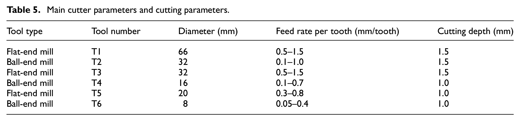
Considering good cutting performance, coated cemented carbide tools were selected in the machining. The cutting tools used in the real processing are from Kennametal Company. The recommended cutter parameters and cutting parameters are shown in Table 5.
Main cutter parameters and cutting parameters.
NC programming based on NX 9.0
CAM software is usually used to conduct NC programming. NX 9.0 (Siemens PLM Software Co., Ltd, Germany) which was widely used in industry was selected in this article. To obtain high-quality surface, the process was divided into roughing, semi-finishing, and finishing processes. The cutting parameters were chosen according to the recommended value from the Kennametal Company tool catalog and the conclusion in section “Modeling and controlling of surface topography in ball-end milling” of this article.
In rough process, the capacity of the machine tool should be fully used to remove the material. The allowance of the subsequent process needs to be well-distributed. Semi-finish process is used to reduce the error left by rough machining process. Moreover, a certain precision can be achieved by semi-finish, preparing for finish processing. In rough process and semi-finishing process, the cutting parameters were mainly chosen according to the recommended value from the tool catalog.
The main purpose of finishing process is to get good machining precision and stable surface topology. Therefore, the tilt angle is set 10° to keep the surface topology consistent according to the conclusion in section “The rear bumper mold process planning” of this article. The simulation results of finishing process based on NX 9.0 are shown in Figure 11.

Simulation for finish process.
The tool path visualization was achieved after programming to find if there was air travel, overcut, or undercut of the manufacturing. After the simulation and visualization of the tool path, all collision and overcut were eliminated.
Conclusion
In this article, parameters’ optimization and tool path planning for specific part rear bumper mold are conducted. The novelty of the article is that it studied the tilt angle for the first time with modeling method in detail. And then the tool path planning for the rear bumper mold based on NX9.0 was proposed, with the process parameters chosen accordingly. The completed work is concluded as follows:
A numerical model considering tool inclination was developed that predicts topography and surface roughness in ball-end milling processes. Since the simulated results remarkably agree with the experimental results, the model can describe the real surface topology correctly.
With the increase in the feed rate per tooth, the surface roughness gets larger. Meanwhile, the radial cutting depth has similar influence on the surface roughness. In the case of the permitted surface roughness, large feed rate per tooth and radial cutting depth can be chosen to obtain high efficiency.
The surface roughness decreases significantly with the tilt angle increasing from 0° to 5°. When the tilt angle is 10°, surface roughness gets the smallest value. What is more, surface roughness increases slightly from 10° to 30°. In other words, the tilt angle can be chosen correspondingly from 5° to 30°. Generally, in order to get a good surface quality, we can choose the best tilt angle 10°. Meanwhile, we can also choose a certain tilt angle from 5° to 30° to satisfy the actual machining process.
The specific rear bumper cutting process was modeled and simulated in NX 9.0. The NC programming and the tool path planning were conducted.
Footnotes
Academic Editor: David R Salgado
Declaration of conflicting interests
The author(s) declared no potential conflicts of interest with respect to the research, authorship, and/or publication of this article.
Funding
The author(s) disclosed receipt of the following financial support for the research, authorship, and/or publication of this article: This work was supported by the National Natural Science Foundation of China (Grant No. 51575321) and National Major Science and Technology Project: High-end CNC Machine Tools and Basic Manufacturing Equipments (Grant No. 2012ZX04006-011).