
Abstract
In engineering practice, most centrifugal compressors use variable inlet guide vanes which can provide pre-whirl and control volume flow rates. As the impeller of a centrifugal compressor passes through the wakes created from the guide vanes, the aerodynamic parameters change significantly. The concept of adding dual slots at the trailing-edge of the guide vanes is proposed for reducing the aerodynamic load on the compressor impeller blades. In this article, the steady and unsteady performances of the new guide vanes are analysed under two compressor operating conditions (winter and design conditions). The results show that the average amplitude of the impeller passing frequency at the leading edge has a 13% decrease under the winter condition, especially at the middle and root parts. Moreover, the dual slots structure has no effect on the overall compressor performance.
Introduction
Recently, most industrial centrifugal compressors have been required to operate over a large range of mass flow rates rather than under one operating condition, with the upper of the compressor operating range being determined by choking and the lower being determined by surge. Variable inlet guide vane (VIGV) is widely used in practice to make the compressor work over a large operating range. The general VIGVs, consisting of a series of flat plates that can be turned to induce a controlled inlet pre-whirl, are usually placed in front of the impellers. Compared to other methods for adjusting flow rates, the simple VIGV system can regulate the condition without compressor shutdown and can be automated by the servomechanism support.
Generally, the VIGV can operate over a range from −20° to +60°. It is found that when working with a large setting angle, the corresponding large incidence angle between the incoming flow and the VIGV produces serious pressure loss and strong rotor/stator interaction due to the wakes created from the VIGV. Meanwhile, because of the wakes, the impellers experience a significant change in aerodynamic parameters, for example, the velocity, the flow angle and the pressure.1,2 This will not only make the aerodynamic performance be worse, but also increases the impeller blade aerodynamic load, causing serious accidents, such as impeller blade fatigue destruction. Thus, for the centrifugal compressor, the related issue is to reduce the interaction between the impeller blades and VIGV to reduce aerodynamic load, resulting in smooth operation and long lifespan.
Most of the published literatures concerning centrifugal compressors with VIGV focused on the control of pre-whirl flow conditions to improve the overall aerodynamic performance of the compressor.3–8 There are also some literatures related to the topic of reducing wakes and the interaction between the stator/rotor. However, regarding centrifugal compressors, the literatures pay attention on the impeller–diffuser–volute interaction.9–11
In Park and Cimbala’s 12 experiments, they found that the two slots configuration outperforms the one slot configuration in rapid wake decay. Corcoran’s 13 work showed that the trailing-edge blowing reduces the Reynolds stress, the vorticity and the velocity fluctuations within one chord length downstream. Naumann’s 14 work showed that in these configurations, discrete jets provide the best results. They both demonstrated that wakes deficits and unsteadiness had been significantly reduced in two-dimensional (2D) aerofoils planer flow. Sirviente and Patel 15 concluded that the wake/jet dissipation rate was increased by swirl for axial flow. Thus, the concepts of trailing-edge blowing have been successfully applied to turbo machinery to reduce the unsteady stator/rotor interaction. Waitz et al. 16 and Leitch et al. 17 found that the flow is more uniform when using trailing-edge blowing, which reduces the unsteady interaction through an axial turbofan. Brookfield and Waitz 18 showed that trailing-edge blowing is effective for reducing the rotor wakes and their mean harmonic amplitudes. Rao et al. 19 demonstrated via an experiment that adding a blowing hole could reduce the unsteady stator/rotor interaction in a turbofan simulator. Lewis et al. 20 suggested using injected water from the trailing-edge to reduce the unsteady load on hydro turbine runner blades. It was found that the amplitude of the runner frequency was reduced by approximately 43%. Lewis et al. 21 also compared the jet flow rates between 1% and 3%, with the optimal jet flow rate being between 1.75% and 2% of the inlet flow rate, and confirmed that the adding of blowing caused a significant global increase in velocity and a circumferential shift in the wakes location.
All of the works previously discussed tended to inject extra flow into the hole and then discharge flow through the dual slots to reduce the wakes. For the purpose of reducing the aerodynamic load on impeller blades and also inspired by these works, we adopt this method for a centrifugal compressor; no evidence has been found in the literature of the application of trailing-edge blowing to centrifugal machines, such as a centrifugal compressor with VIGV. However, the additional mass flow will significantly affect the working condition of the centrifugal compressor and then influences the indicators such as discharge pressure and efficiency; 22 the extra flow injection device will also make the turbomachine more complicated. Therefore, in this article, we only adopt the dual slots structure on the VIGV without the extra flow injection in compressor operations. For most centrifugal compressors, the semi-open impellers are used for the first stage to obtain a high pressure ratio, and the leading edge of the impellers suffers from the strong aerodynamic load due to the waves created by guide vanes. Therefore, we especially focus on the aerodynamic load on the impeller leading edge. The numerical simulations prove that this new structure could reduce the aerodynamic load on the impellers.
The remainder of this article is organized as follows. Section ‘Geometry description’ describes the dual slots structure on VIGV. Section ‘Computational considerations’ describes the computational consideration. The analysis and calculation results are shown in section ‘Results and discussion’. Finally, section ‘Conclusion and future work’ provides some concluding remarks.
Geometry description
VIGV dual slots geometry
As introduced before, the dual slots configuration outperforms the single-slot configuration in wakes decay and further reduces the aerodynamic load significantly. Hence, the dual slots structure without extra air injection is employed for the VIGV in this compressor simulation. Figure 1 gives the flow domain and cross section of the dual slots structure. The hole is located along the guide vanes’ pivot axis, and we select an elliptical shape for the hole where the major axis is a = 20 mm and the minor axis is b = 10 mm. The hole extends from the vanes tip to the vanes root but does not penetrate the VIGV. With the increase in the radius, the chord length of the VIGV and the area of the hole from the tip to the root gradually increase as well. Opening up two channels to exchange the fluid between the hole and the trailing-edge space is referred to as the dual slots structure and the width of the slot is d = 1.5 mm. The two interfaces are the only connection between the main flow and the dual slots flow. Meanwhile, the external linkage of the guide vanes installation and the texture of the guide vanes have been neglected.
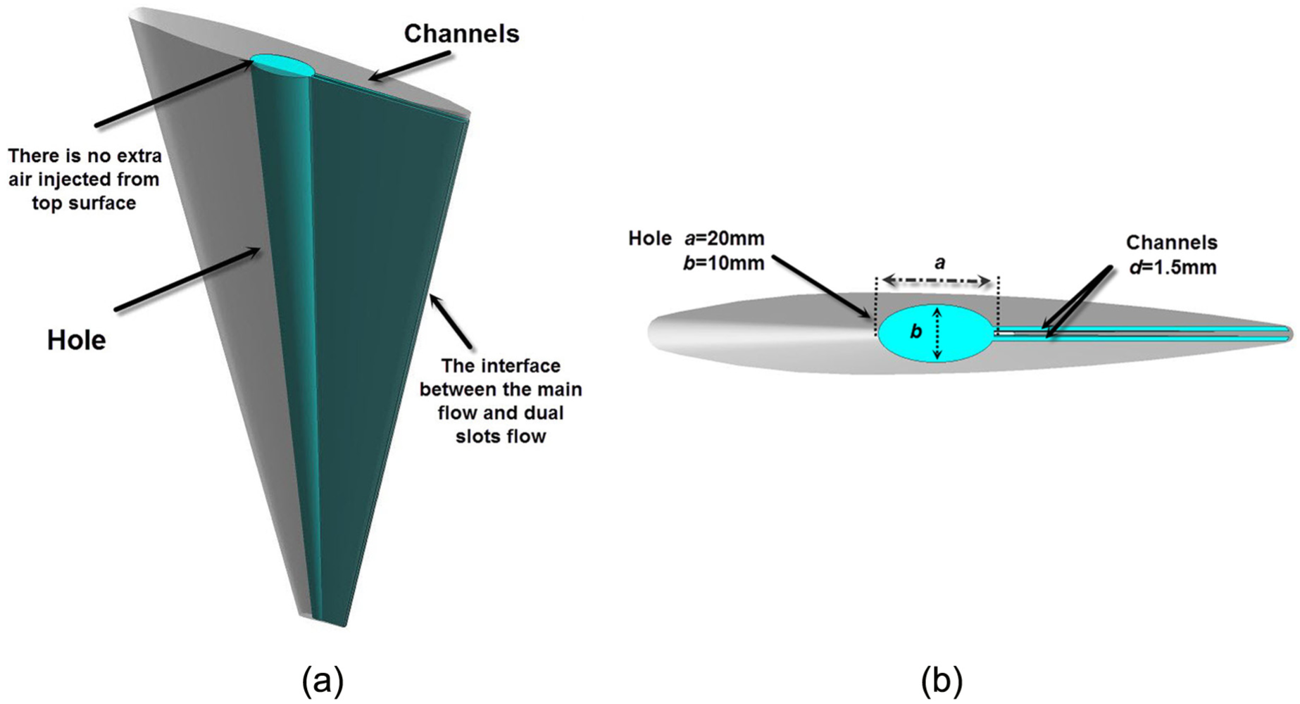
Studied VIGV with dual slots model: (a) flow domain and (b) cross section.
The difference between this structure and reference structure is that the hole with trailing-edge dual slots does not encounter any injection flow from the outside of the compressor during the simulation. However, with no extra air, the main flow will be transferred into our structure to compensate the wakes. Based on the pressure gradient between the VIGV trailing-edge and the hole, the air flows in and out of the dual slots structure at different spans of the VIGV. This part of the air can affect the wakes intensity and further affect the aerodynamic load on the following impeller.
Centrifugal compressor geometry
For the sake of testing the dual slots structure, this article selects the centrifugal compressor model with two different guide vanes set angles (Figure 2) for simulation, which is used for air separation. It involves a typical single stage compressor with 12 flat plate VIGV (Ng), 19 impeller semi-open blades (Ni) and 20 diffuser vanes (Nd). Ng, Ni and Nd, respectively, represent the number of VIGV, impeller blades and diffuser vanes.
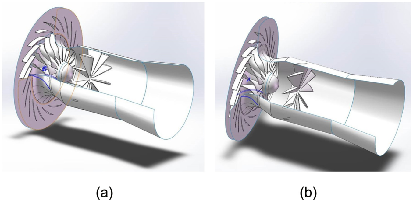
Model of the centrifugal compressor with two different guide vanes set angles: (a) guide vanes set angles of 0° and (b) guide vanes set angles of +38.6°.
The rotation speed of this compressor is nearly constant under different conditions, and the VIGV are required to operate over a range of setting angles from −30° to +70° to provide a controllable flow rate and pre-whirl. Under the design condition, the VIGV work in the fully open state, that is, the set angle is 0°. When running in winter condition, the VIGV angle is set as +38.6° to reduce the volume flow rate, resulting in a positive pre-swirl. The compressor performances under the two conditions are summarized in Table 1.
Summary of the compressor performances under the design and winter conditions.

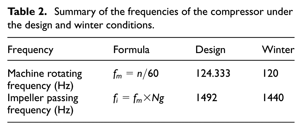
During the compressor unsteady simulation, the main frequencies of the aerodynamic load appear at the impeller passing frequency and the machine rotating frequency. The impeller passing frequency, which corresponds to the time when the impeller rotates through the nearest two guide vanes, is the dominant frequency for pressure pulsation in the field of rotating machinery. Table 2 shows the machine rotating frequency and the impeller passing frequency of the compressor under the design and winter conditions.
Summary of the frequencies of the compressor under the design and winter conditions.
Computational considerations
In this article, all simulations are carried out using ANSYS CFX 14.0. The air ideal gas is used as the working fluid and the computational fluid dynamics (CFD) simulation domain includes three parts: the VIGVs with dual slots, the impellers and the diffusers. The full passage numerical simulation model of the compressor adopts the actual size for processing, ensuring the accuracy of the flow region and the application value to engineering. Note that because we focus on the guide vanes–impeller blades interaction, the volute of the compressor is neglected. In the simulation model, the total energy equation is selected for the heat transfer, the high-resolution advection is used for both steady and unsteady simulations, and the second-order backward Euler is used for unsteady simulation. To ensure convergence, the root mean square (RMS) residual target is set to 1e−5 for the pressure and velocity components. The steady simulation result is used as initial condition for the unsteady simulation. During the unsteady simulation, the total computing time is set to 15 cycles of impeller rotation for each operation condition to obtain stable and precise aerodynamic data regarding the impeller blades. The time step size setting is related to the compressor operation condition, that is, 360 time steps per impeller rotation cycle are chosen for each case. The loops of each time step coefficient are set from 3 to 10 to ensure convergence. As the volute is neglected, the CFD simulation domain can be regarded as a circumference symmetric model. Hence, the monitor can be set on a single impeller blade in the rotating coordinate system. Note that the rotating coordinate system speed is related to the operation condition, which ensures that the monitor always obtains the information from the impeller blade. During the simulation, the flow data are saved at the monitoring points. Because the research purpose focuses on the dual slots’ effect on guide vanes wakes, all the six points are placed at the leading edge of the impeller blade from the hub to the shroud (0.1 span, 0.5 span and 0.9 span plane along the height of the impeller blade). Among the six monitors, three points are on the suction side (Sroot, Smid and Stip) and three points are on the pressure side (Proot, Pmid and Ptip; see Figure 3). Then, we record the data from each time step. After the unsteady simulation, the pressure signals of these monitoring points are calculated using fast Fourier transforms (FFT) to obtain the dominant frequency and the pulse amplitude.

Locations of monitoring points.
Turbulence transport equations and boundary conditions
Turbulence transport equations
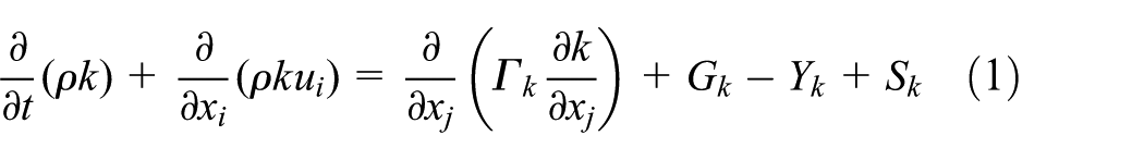
In this analysis, the k − ω-based shear stress transport (SST) (transport of the turbulent shear stress) turbulence model is used. The SST model is based on the equation of turbulence energy and the equation of diffusion rate. This model is designed to give a highly accurate prediction of the onset and the amount of flow separation with adverse pressure gradients.
The equation of SST

where
Boundary conditions
In the full passage steady and unsteady numerical simulations, the boundary conditions are set as follows: the flow domain inlet is located at the upstream of the VIGVs, the total pressure and total temperature are used, the domain outlet is just downstream of the diffuser vanes, and because the working medium is a compressible fluid, the mass flow rate outlet is used. The no-slip condition is set for the hub, shroud and all blade surfaces; the rotating and stationary components are connected by the general grid interface (GGI); the frozen rotor interface is used for steady simulation because this type of interface does not produce any mixed state in front of or behind the impeller; the transient rotor–stator interface, which takes into account all the transient flow characteristics and allows for a smooth rotation between components, is used for unsteady simulation.
Grid refinement
In this article, for the blade passage, we use the ANSYS turbo-grid to generate the structured mesh, and for the flow domain of the dual slots, we use the commercial mesh generator Gambit to generate the unstructured mesh (Figure 4). Then, the one periodic passage is copied to the full wheel model.

3D mesh of different parts of the compressor: (a) guide vane, (b) dual slots and (c) impeller blade.
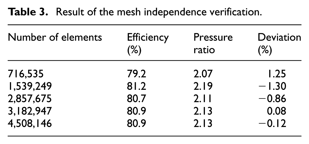
Generally, a mesh independent study should be conducted to investigate the effect of mesh density and to determine how fine of a mesh is appropriate for simulation. Table 3 shows the simulated results at the design operation point with different mesh numbers. The ‘Deviation’ in the third column indicates the difference value of the mass flow between the outlet and the inlet. It is observed that when simulating with more than 3,182,947 elements, the simulated results are almost the same as the actual. Thus, considering the simulation accuracy and the computing time, the 3,182,947 mesh elements with a 19.45° minimum orthogonality angle is used in subsequent calculations. Moreover, Figure 5 shows the values of Y plus on the blade and the inlet guide vanes, which are found to satisfy the requirement of the SST turbulence model.
Result of the mesh independence verification.

Values of Y plus on blade surface: (a) guide vane and (b) impeller blade.
Results and discussion
In the following section, the results and detailed analysis of the steady and unsteady simulations will be discussed. The size of the dual slots will be investigated as well. In each case, the model without dual slots is presented for comparison purposes. To be fair, the same boundary conditions and grid are used for models with and without dual slots under the same working conditions.
Steady simulation
Steady results offer the overall performance and the detailed flow phenomenon of the compressor. Figure 6 shows the characteristic curves of the compressor with/without the dual slots structure under the design condition and the winter condition, respectively. Although the dual slots are added on the VIGV trailing-edge, the parameters remain nearly consistent under both conditions. This means that adding the trailing-edge dual slots has no influence on the compressor performance.
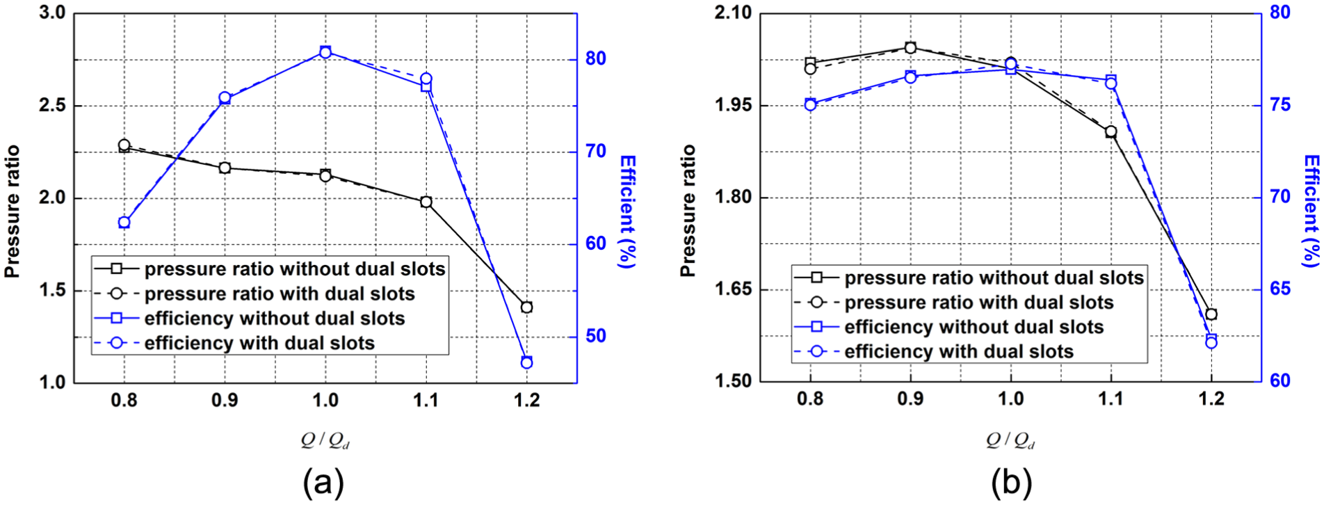
Characteristic curve of the compressor under two conditions: (a) design condition and (b) winter condition.
The pressure ratio and the compressor efficiency are calculated as follows


where
The velocity contours with/without the dual slots structure under the design condition are shown in Figure 7. Low velocity regions are clearly seen in the one periodic passage, with the regions being wakes. The wakes appear at the VIGV trailing-edge and extend to the impeller blades. When passing through these wakes, the impeller blade experiences unsteady aerodynamic load. Under the steady simulation result, it is difficult to observe the obvious effect of adding dual slots on the VIGV. Therefore, the unsteady simulation is required for testing the effect of the dual slots model.

Velocity distribution in one periodic VIGV passage under the design condition: (a) without dual slots and (b) with dual slots.
Although it is hard to observe the obvious effect of the dual slots structure in Figure 7, we can analyse the flow phenomenon when adding the dual slots. Figure 8 shows the pressure distribution at the meridional plane of VIGV flow domain. It is observed that at the VIGV trailing-edge, the pressure of the root is higher than that of the tip. This is due to the longer circumference direction distance near the root. According to the pressure gradient distribution near the VIGV, it drives the air to flow from the VIGV root to the VIGV tip.

Pressure distribution at meridional plane of VIGV domain.
Figure 9 shows the pressure contours at different heights of the VIGV. At the 0.9 span (near the root) of the VIGV, the pressure at the hole region is clearly lower than the pressure near the trailing-edge region. At the 0.5 span (middle span) of the VIGV, the pressure at the two regions is almost the same. At the 0.1 span (near the tip) of the VIGV, the pressure in the hole is higher than that near the trailing-edge.

Pressure contours of the VIGV trailing-edge in design condition: (a) 0.9 span, (b) 0.5 span and (c) 0.1 span.
According to the pressure distribution near the trailing-edge of the VIGV, we infer that in the dual slots structure, the air flows into the dual slots near the root region and flows out near the tip part. Figure 10 shows the streamline in the dual slots structure. The flow performance in the dual slots has a ‘C’ shape, and the flow phenomenon in the dual slots will affect the wakes distribution, that is, which could compensate for the wakes that act on the impeller blades root and also make deficits which act on the impeller blades tip. However, the air speed in the dual slots structure, that is, approximately 5 m/s, is not very high. This means that only some flow passes through the dual slots. Therefore, we think that under the design condition, the dual slots structure does not have an obvious effect on wakes.

Streamline at the VIGV dual slots model under the design condition.
Under the winter condition, the pressure distribution at the meridional plane is similar to that under the design condition as shown in Figure 8. However, under this condition, because the set VIGV inlet angle is + 38.6°, it leads to large incidence angles and then a reduction in volume flow rate and efficiency, which especially affects the flow behaviour near the VIGV. Therefore, when the flow passes through the VIGV, there is an obvious pressure difference between the VIGV pressure side and the suction side (Figure 11). The low pressure region is due to the boundary layer separation on the suction side of the VIGV, caused by the large incidence angles. However, the degree of the boundary layer separation is different from the tip to the root of the VIGV: it becomes more and more apparent with the decrease in the VIGV chord. Compared to the design condition, the wakes in winter condition are larger because of the separation of the boundary layer. The pressure distribution between the hole and the trailing-edge is similar to the design condition. At the 0.9 span of VIGV, the pressure in the hole region is lower. At the 0.5 span of the VIGV, the pressure at the two regions is almost the same. At the 0.1 span of the VIGV, the pressure in the hole is higher. However, compared to the design condition, the difference value of the pressure between two sides of the trailing-edge of VIGV appears under the winter condition.

Pressure contours of the VIGV trailing-edge under the winter condition: (a) 0.9 span, (b) 0.5 span and (c) 0.1 span.
The streamline of the flow in the dual slots under the winter condition is similar to that under the design condition, that is, the air flows into the dual slots near the root region and flows out near the tip part (Figure 10). However, because the pressures of the two sides of the trailing-edge of the VIGV are different, the flow phenomena between the slots are different as well. The velocity distribution at the interface between the dual slots and the main flow is shown in Figure 12. The two monitor lines at the interface between the dual slots and the main flow are shown in Figure 12(a). The velocity direction of the flow is same as the VIGV setting angle; the positive and negative values represent, respectively, the outflow and inflow in the dual slots structure, and Lp and Ls represent the lines near the pressure and suction sides, respectively (Figure 12(b)). According to the previous analysis, the pressure on the suction side is higher near the VIGV root. Hence, the higher pressure difference leads more air to flow into the slot near the suction side. As the radius decreases, the velocity increases first and then decreases until no air flows into the dual slot near the middle span of VIGV. The velocity near the suction side is always higher in this part. From the middle to the tip, the air that flows out of the dual slots steadily increases. The velocity on the suction side is higher, as the separation of boundary layer. Compared to the design condition, more flow has passed the dual slots, for example, the maximum speed is near 30 m/s. Thus, under the winter condition, the dual slots affect the wakes more seriously, that is, the dual slots will obviously change the aerodynamic load on the impeller blades.

Velocity distribution for the VIGV dual slots structure under the winter condition: (a) the locations of the two lines and (b) comparison of velocity distribution at two lines.
For both conditions, the flow phenomena in the dual slots are illustrated. Therefore, we infer that the air in the dual slots can be regarded as the compensation for the wakes near the VIGV tip, which reduces the aerodynamic load on the impeller blade root part. Based on the phenomenon under the winter condition, we can predict that if the set VIGV opening angle is negative, the dual slots will have the effect as well.
Unsteady simulation
To ensure the accuracy of the unsteady simulation, the impact of the time step size in unsteady simulation is investigated. Figure 13 presents the time history oscillations of pressure for one selected point with two unsteady time step sizes (1 step per degree and 0.5 step per degree) for nearly seven complete runner revolutions. It is observed that the two curves with different time step sizes are very similar but still have some differences. Therefore, one degree per time steps can achieve more precise data.

Time history oscillation of pressure with two different time step sizes.
The frequency spectrum of the pressure fluctuation of different monitors is calculated using FFT. Figure 14 shows the frequency spectrum of pressure fluctuation of all the six monitors under the design condition while Figure 15 shows the fluctuation of all the six monitors under the winter condition. As expected, the 1492 Hz impeller passing frequency dominated the spectrum under the design condition, and 1440 Hz dominated the spectrum under the winter condition. From the results of the model with and without dual slots, we find that the dominate frequencies are consistent and that no other response frequencies appeared. Thus, we can conclude that the dual slots structure has no effect on the frequency distribution for both two conditions.

Frequency spectrum of pressure fluctuations of all the six monitors under the design condition: (a) without dual slots and (b) with dual slots.

Frequency spectrum of pressure fluctuations of all the six monitors under the winter condition: (a) without dual slots and (b) with dual slots.
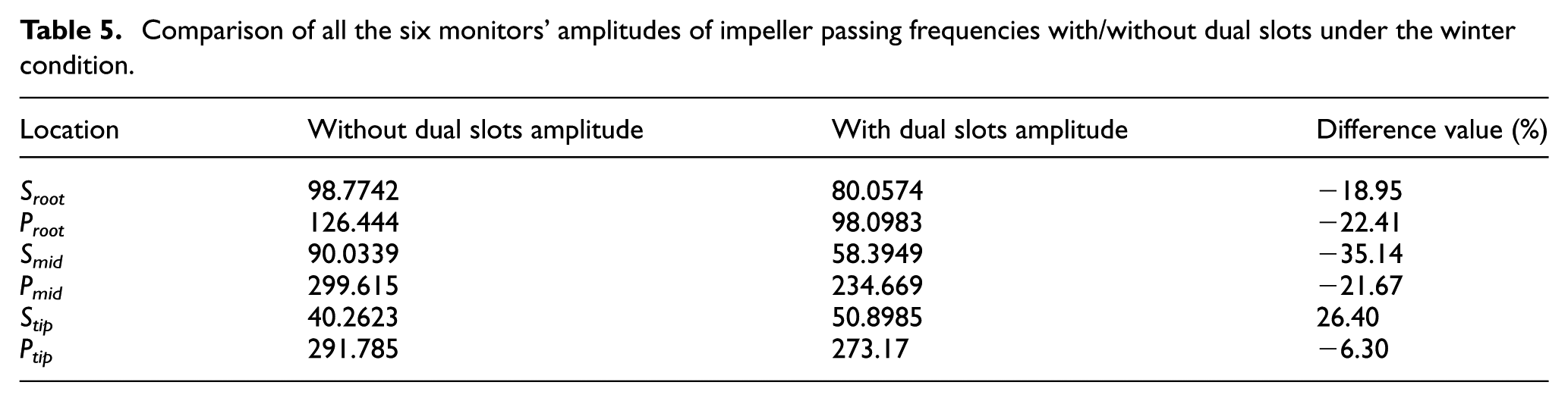
Table 4 presents the amplitude of the monitor passing frequencies of all the six monitors under the design condition, the difference value in the third row indicates the difference value of the amplitude between the VIGV with and without dual slots structure. It is observed that the difference value of each monitor between the models with/without dual slots is small, just as for the aforementioned steady results, and that the dual slots make less effect on the wakes. However, when the dual slots are added to the VIGV under the winter condition, there are significant differences between the two models, as shown in Table 5. For the middle and root monitors, the average amplitudes at the impeller passing frequency are reduced by approximately 24%. Of course, we find that the amplitude of point Stip is 26% higher in the new model. This is due to the phenomenon in which the air flows into the dual slot near the VIGV root. Therefore, we can conclude that adding dual slots has an obvious effect, reducing the aerodynamic load on the impeller blades, the average amplitude at leading edge has a 13% decrease, especially for the middle and root part although it increases the aerodynamic load on impeller near the tip part.
Comparison of all the six monitors’ amplitudes of impeller passing frequencies with/without dual slots under the design condition.

Comparison of all the six monitors’ amplitudes of impeller passing frequencies with/without dual slots under the winter condition.
Comparison with different slots sizes
The dual slots structure plays an important role in this study in reducing the aerodynamic load; thus, the size of the slots should be investigated to evaluate the effect on the wakes. Therefore, we offer two different sizes, that is, d = 1 mm and d = 2 mm, to compare with the original slot size, that is, d = 1.5 mm. Figure 15 presents the streamline comparison of the dual slots with different slots sizes under the winter condition. We find that the flow phenomenon did not change much as shown in Figure 16. Similar to Figure 6, the air still transfers from the VIGV root to the VIGV tip.

Streamline at the VIGV dual slots using different sizes under the winter condition: (a) d = 1 mm, (b) d = 1.5 mm and (c) d = 2 mm.
However, when d increases, the velocity increases. We present the mass flow comparison using different sizes of d through the two interfaces. The two surfaces are defined at the interfaces, as shown in Figure 17(a). The positive and negative values of the mass flow represent the outflow and inflow of the dual slots structure, respectively; Sp and Ss represent the surfaces near the pressure and suction side, respectively (Figure 17(b)).
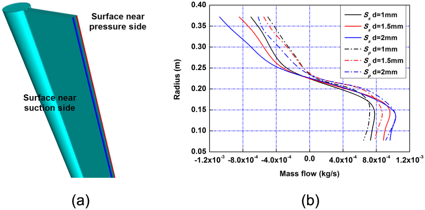
Streamline at the VIGV dual slots using different d sizes under the winter condition: (a) the locations of the two surfaces and (b) comparison of the mass flow distribution on two surfaces.
When the slot size increases, more air flows into the dual slots structure, which could compensate the wakes. When the slot size decreases, less air flows into the dual slots structure. Furthermore, we compare the amplitudes of the impeller passing frequency using different slot sizes under the two conditions (Figure 18).

Comparison of the amplitudes of impeller passing frequency using different slot sizes under the two conditions: (a) design condition and (b) winter condition.
Similarly, the dual slots have no obvious effect on the aerodynamic load under the design condition, with the maximum difference value being less than 6%. Under the winter condition, it is found that the aerodynamic load is affected by the slot size significantly. Compared to d = 1.5 mm, when d = 1 mm, the effect of the dual slots on the aerodynamic load is weak. With d = 1 mm, the aerodynamic load increases at the middle and root parts and decreases at the tip part, and the average amplitude at leading edge has a 6% decrease. When d = 2 mm, the aerodynamic load decreases at the middle and root parts significantly, but increases at the tip part by nearly 43%. The average amplitude at leading edge has a 9% decrease. The result of the aerodynamic load agrees with the flow phenomenon analysed above.
Conclusion and future work
The VIGVs are widely used in compressors. However, the VIGV create wakes, resulting in serious pressure loss and strong rotor/stator interaction. Therefore, based on the previous research, the author suggests adding the trailing-edge dual slots structure to VIGV. In this article, the flow phenomenon through the centrifugal compressor with/without dual slots structure under two operation conditions is obtained by numerical simulation, the pressure fluctuation on impeller blades is also investigated. By adding the trailing-edge dual slots, the pulse amplitude is reduced, that is, the aerodynamic load on the centrifugal compressor impeller blades is reduced. The reduction of aerodynamic load could be beneficial for smoother operation and increase the lifespan of the compressor. Based on the results discussed above, the conclusions are listed as follows:
Adding the trailing-edge dual slots structure has no significant effect on the compressor characteristic under two operating conditions;
Analysis of pressure and velocity revealed that the air transfers from the VIGV root to the VIGV tip through the dual slots, which could compensate for the wakes that act on the impeller blades root and also make deficits which act on the impeller blades tip. More air flows into the dual slots structure as the VIGV set angle increases.
Under both two operating conditions, the distribution of impeller passing frequency which dominated the spectrum does not change despite adding the dual slots. Under the design condition, the dual slots structure gains nearly no reduction of the aerodynamic load. Under the winter condition, the dual slots structure produces a nearly 13% reduction of the amplitude of the impeller passing frequency at leading edge, although it only increases the amplitude near the tip part of the impeller. Therefore, we can predict that the dual slot structure will have an obvious effect on the aerodynamic load when other large VIGV angles are set.
The slot size d significantly affects the reduction of the aerodynamic load on the impeller blade under the winter condition. A smaller slot size has less effect on the reduction of the aerodynamic load. A larger slot size has more effect on the reduction of the aerodynamic load at the middle and root parts; however, it also produces a higher aerodynamic load at the impeller tip part.
Future work will focus on the compressor performance with different setting angles of the VIGV with dual slots, especially when the compressor operates under off-design conditions (stall and surge). For the structure, we will evaluate the effect of the position of the hole and the height of the dual slots on the wakes.
Footnotes
Appendix 1
Academic Editor: Thirumalisai S Dhanasekaran
Declaration of conflicting interests
The author(s) declared no potential conflicts of interest with respect to the research, authorship, and/or publication of this article.
Funding
The author(s) disclosed receipt of the following financial support for the research, authorship, and/or publication of this article: The authors appreciate the financial support from the Research and Innovation in Science and Technology Project of Liaoning Province (201303002), the National Program on Key Basic Research Project (2015CB057301) and the Collaborative Innovation Center of Major Machine Manufacturing in Liaoning.