
Abstract
This article focuses on evaluating the dynamic behavior of ballast mixed with tire derived aggregate as an economic and environmental preserving method to obviate the rigidity problems in railway tracks. For this purpose, the ballast was mixed with 0, 11, 22, and 33 volume percentages of tire derived aggregate in a loading chamber and was examined under different types of dynamic loads such as Sweep sine imposed by a shaker on a rigid square plate. Considering the plate as rigid foundation resting on ballast mixed with tire derived aggregate as subgrade, frequency response functions of both foundation and subgrade were calculated by recorded accelerations and force using the installed accelerometers on loading plate and the wall of loading chamber and load transducer in shaker tip. The obtained results for pure ballast first proved that Sweep sine shaker test leads to more smooth spectra in comparison to other shaking methods. The obtained values for subgrade stiffness and damping ratio showed considerable decrease and increase with respect to increase in tire derived aggregate percentage in ballast mixture. As an optimum percentage of tire derived aggregate, values around 10 can be proposed for practical uses.
Introduction
Ballasted railways tracks are known as one of the traditional modes of transportation, and their good performance remarkably depends on the mechanical behavior of the ballast material. This granular material has main duties such as reducing under sleeper pressure to allowable subgrade bearing capacity, providing the acceptable vertical resiliency for railway track, assistance in track drainage, damping the induced noise and vibration due to wheel impacts on rail, and so on. Parallel to railway route operation and accumulating of the passing traffic, this granular material gradually will be degraded due to two simultaneous mechanisms of settlement and particles breakage. Moreover, the ballast fouling is an important reason which magnifies the ballast degradation. This phenomenon is partly created by ballast particles breakage due to wheel load passing and some other causes such as tamping, chemical weathering, freezing and melting, and environmental sands and dust. 1 For instance, sand dune movement toward railway tracks located in desert areas causes ballast fouling, which increases the total track stiffness and raises the track components degradation and rolling stock as well. Moreover, its undesirable effects in increasing the train induced noise and vibration are remarkable. One of the solutions to obviate the track rigidity due to the mentioned problems of ballast, which has been praised by researchers and railway owners, is installing special rubber pads under the sleepers which have been called under sleeper pad (USP). The use of these pads cause some positive effects on the railway tracks performance such as improving track quality, decreasing the track life cycle costs, 2 reducing the stress applied on the track components and reducing the ballast thickness. Moreover, they make the under sleeper pressure distribution, 3 more uniform and causes in smaller rail corrugations with long wavelengths in small curves, 4 creating very gradual change in track stiffness at transition zones,5,6 and finally they decrease the train induced vibrations in surrounding environment.
The other solution which is usually utilized for modification of ballasted track stiffness and reduction of the ground-borne vibrations is spreading the under ballast mat (UBM) beneath the ballast layer. This material has shown acceptable long-term performance in isolating structure-borne noise on railway lines and in increasing the track geometry stability and reducing the ballast compression which leads to reducing the maintenance costs.
In this matter, Wettschureck7,8 has shown the suitable performance of UBM material in the reduction of ground-borne vibration in railway tunnels and isolation of vibration and structure-borne sound. In another study, Müller 9 discussed about the ballast mat efficiency in controlling vibration and ground-borne noise for open lines. In another study, Müller 10 has investigated the UBM insertion loss in the framework of technical report for International Union of Railways (UIC). In another research, Bruni et al. 11 developed a Numerical model in conjunction with some experimental studies to show the ballast mat effect on the reduction of train induced vibrations in metro lines and especially in tram turnouts. Moreover, some recent field observations were reported by Dold and Potocan 12 which confirm the reliable long-term behavior of ballast mat over the bridge deck in controlling the ballasted track resiliency and increasing the ballast life.
Tire derived aggregate (TDA) is a multi-purpose rubber product derived from processing used tires into consistent shapes ranging between 25 and 300 mm in size which can be categorized as one of the most cost-effective examples of waste tire recycling and is one of the most environmentally friendly uses for civil engineering problems. In the recent decade, using TDA as subballast layer in ballasted track for controlling the train induced vibrations has attracted railway designers and owners. In this regard, in Korea, a series of field experiments were carried out to assess the reduction effect of railroad transport vibration by utilizing waste tire chips. The field tests were carried out with variation of the thickness of the waste tire layer (0, 20, and 50 cm) and the magnitude of the vibration (23 and 33 Hz). The amount of vibration reduction by 20- and 50-cm-thick waste tire layers measured 3 m from the 23-Hz vibrating source was 16% and 34%, respectively. Under identical conditions, the amount of vibration reduction was 30% and 36%, respectively, with an increase in the frequency of vibration to 33 Hz. Therefore, it was found that the vibration reduction effect from waste tire was more significant at greater thickness of layer and higher vibration frequency of 33 Hz. 13
In another study, many field tests were performed in May 1999 at a specially prepared site at the Chicago Grade Landfill in Templeton, California. In the mentioned study, a stationary impact and three mobile devices were used as vibration source. A force transducer at the base of the tube measured the force which was transmitted to the surface of the test pad. The vibration velocity transducers (geophones) then determined the vibration level of this impact at various locations adjacent to each test pad. Results showed that the attenuation or insertion loss extends from approximately 6 to 200 Hz, and it was indicated that TDA performed as damper layer with the best performance at 20-Hz frequency. 14
The second field test consisting of a ballast and tie track installation resulted from the need of the Santa Clara Valley Transportation Authority (VTA) to provide ground-borne vibration reduction from future light rail transit (LRT) operations along the VTA Vasona Corridor. Results indicate that the tire shred layer is very effective in the frequency range above 31.5 Hz and marginally effective from approximately 12.5 or 16 Hz up to 31.5 Hz. In addition, results show that there appears to be some benefit in the higher frequency (>63 Hz) in extending the tire shred layer out to 2.66 m from centerline and upturning the end. 15 Three extensive tests during 2005, 2006, and 2009 were held on the Vasona Line of the VTA. The third set of tests were undertaken to verify the performance of the TDA underlayment after approximately three and one-half years of revenue operations. The outcome of all three tests has shown that the use of TDA underlayment beneath ballast and tie track provides for vibration reduction generally beginning at frequencies above 16 Hz. 16 Finally, in 2010, another field test in Denver was held. Tests were conducted at four TDA sites and one control site (with standard ballast and tie). On average, the TDA underlayment at Denver Regional Transportation District (RTD) provides a ground-borne vibration reduction of about 3 dB between 25 and 31.5 Hz and reductions of 8–14 dB between 40 and 160 Hz. The recent TDA vibration reduction test results at Denver RTD are similar to those obtained from recent TDA vibration tests (by Wilson, Ihrig & Associates [WIA]) at the VTA light rail system in San Jose, CA. 17 Compared to other types of vibration mitigation measures tested (by WIA) at the San Francisco, CA Muni light rail system, the TDA vibration reduction performance at RTD was found to be equal or superior to that of a ballast mat and not as effective as a floating slabtrack installation.
Beside the existing measures such as using TDA layer as subballast, installing of USP and UBM in ballasted track in order to control the ballast breakage, reduce the train induced vibration and in overall increasing the track resiliency, this study attempts to introduce a new approach for more efficient utilizing of TDA material in ballasted railway track. In this regard, the idea of mixing the ballast material with TDA with the same gradation is proposed. Basically, it seems that this new application for TDA can be supported by the following reasons:
Sand dune movement in desert regions (for instance, the central desert of Iran) creates many problems such as track closure, excessive track rigidity due to filling of the ballast voids by sand, excessive dynamic loads on track, rail breakage, fastening attrition, sleeper breakage, and so on. In order to mitigate the associated problems of the railways in desert areas, particularly with the potential of sand dune movement, the mixture of TDA and ballast decreases the excessive track stiffness and also increases the ballast damping which these two positive effects can obviate the aforementioned problems in ballasted railway track.
One of the conventional methods to construct transition zone between ballasted track to slabtrack or railway bridge and railway tunnels is declining the stiffness of the more stiffer section. From this point of view, utilizing the TDA mixed with ballast can be considered as a suitable approach similar to USP or UBM installation.
Although, in previous studies the efficiency of TDA as subballast layer in reducing the train induced vibrations has been demonstrated, but the TDA layer disturbance during tamping operations can be considered as main shortage of this method. However, mixing TDA with ballast preserves the same advantages of ballast during the tamping operation without losing the TDA material efficiency.
As one of the serious issues during the ballast tamping operation is ballast breakage and also the wearing of tamping tines and scraper fingers of ballast cleaner machine, the proposed material can moderate these damaging effects. This is because of softer behavior of TDA with respect to ballast particles in interaction with maintenance apparatuses.
Using TDA mixed with ballast can decrease the breakage and wear of ballast particles under passing traffic. This is achievable because of the resilient nature of TDA compared to the ballast particles.
As the proposed TDA for mixing with ballast in this study has the same ballast gradation so its effect on track drainage capacity is ignorable. Moreover, the ignorable water absorption of TDA confirms its good performance during the freeze and thaw cycles during track operation.
Besides the above-mentioned benefits which preliminarily justify the application of TDA mixed with ballast in ballasted tracks, some other deficiencies can be assumed such as reductions in track vertical and lateral stiffness which may cause some malfunctioning in track stability under passing loads. In this regard, the authors have planned a very extensive laboratory and in field tests program to evaluate the physical and mechanical behavior of TDA mixed with ballast compared to conventional ballast material. Also, any eventual instability of the mixture will not be a source of concern, because there are many methods to improve the stability of ballast. Indraratna et al.18,19 carried out research works about coal fouled ballast that show reduction of mechanical interlocking by the fouling coal and solving the problem using geogrid.
The present study is the first effort in quantifying the stiffness and damping of the new proposed material. So far, modal laboratory test has not been used for system identification of ballast, so the ballast and ballast mixed with different percentages of TDA were tested using Sweep sine modal shaker and the results were compared. In the modal tests conducted in a loading chamber, a square semi rigid steel plate resting on subgrade material was loaded by a shaker. The system response to the imposed excitations were recorded by installing vertical accelerometers on both loading plate and one of the walls of box chamber. Assuming the loading plate as rigid foundation, the measured frequency response functions (FRFs) with this method were curve fitted with simple single-degree-of-freedom (SDOF) model assuming mass of the plate and damper–spring of the subgrade. Consequently, the obtained stiffness and damping for various subgrades were compared in a quantified manner and the effects of TDA on these two factors were evaluated.
Material properties
In this study, for better shear locking between ballast and TDA particles and preserving the ballasted track drainage, the particle size distribution of TDA was chosen as the same as that of dolomite ballast according to standard ballast gradation of AREMA NO. 4 (Figure 1). The specific gravity of dolomite ballast and TDA were measured as 13.4 and 5.66 kN/m3, respectively, based on ASTM. Figure 2 shows the sample of TDA used in laboratory. It should be noted that the examined TDA has been prepared by shredding of used tires of trucks with no steel belt. Table 1 shows the results of direct shear test (DST) on ballast mixed with TDA that shows shear strength parameters of the material for each mixture. It should be noted that the DSTs have been conducted on the box with 300 mm × 300 mm dimensions according to ASTM D3080. 20

Particle distribution curve of the ballast mixed with TDA.
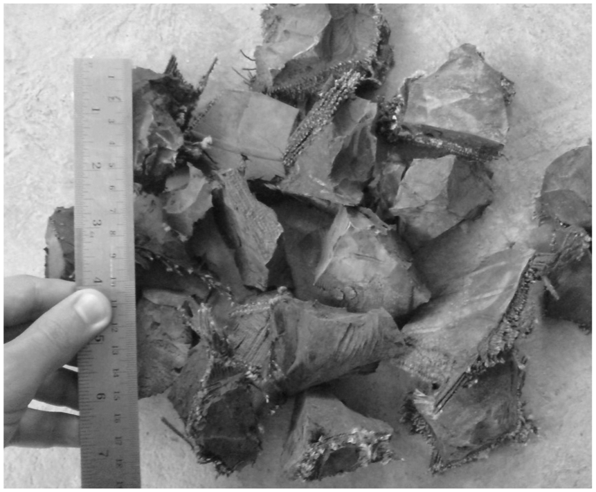
A sample of TDA used in the experiment.
TDA effect on ballast friction angle.

TDA: tire derived aggregate.
Laboratory tests program
Different operation conditions along the railway track and different forces and also difficulties around analyzing complex structures, like ballasted track, suggest us to perform an experiment with known condition in order to provide reliable information about the vibration behavior of ballast as well as ballast mixed with TDA. To study the effect of TDA on the dynamic behavior of ballast, different volume percentages of TDA were mixed with ballast and the mixtures were examined by modal analysis apparatuses in a loading chamber. Overall, four experimental tests were performed on pure ballast and ballast including 11, 22, and 33 volume percentage of TDA. It should be noted that each mixture was built and tested three times and the average of the results were presented. In the following, some details about the procedure of sample preparation, instrumentation and loading procedure, and modal testing are presented.
Sample preparation
For conducting the modal test on pure ballast as well as mixture of ballast and TDA, a steel chamber with dimension of 1.2 m × 1.2 m in plan and 1 m in height was filled up with the materials and a 16.76-kg steel loading plate with dimension of 30.5 cm × 30.5 cm and thickness of 25 mm was placed at the center of the chamber over the material. Figure 3 shows the used chamber for the laboratory tests.

Used chamber for modal test.
For Test 1, each 10-cm ballast layer was first weighted and then dropped in the chamber box. In continue, the ballast layer was shed and then compacted using a 28-kg laboratory roller by 25 passes to reach the maximum dry density of 17.3 kN/m3. Figure 4(a) shows compaction of pure ballast by the roller. Likewise, ballast mixed with different percentages of TDA was prepared for Tests 2, 3, and 4. It should be emphasized that the mixing of ballast and TDA was performed by a laboratory mixer to guaranty the well mixing of the materials and avoiding segregation. Figure 4(b) shows the under preparation sample for Test 4.

Sample preparation: (a) compaction of pure ballast by roller and (b) the ballast mixed with TDA.
It should be mentioned that because of the limited dimensions of loading chamber, some boundary effects may arise during the laboratory modal test, but this condition is the same for the whole of the tests. So it can be stated that investigating the results in a comparative manner can be useful for understanding the TDA effect on the dynamic performance of ballast material.
Instrumentation and loading procedure
One shaker was used to apply the vertical vibrational force on plate. The input force was measured with a transducer located in the shaker tip (Figure 5(a)). The output of the system was measured by means of three accelerometers. One was mounted vertically on the plate as near as possible to the shaker tip to satisfy symmetric condition of the system to measure driving point accelerance (acceleration to force FRF measured with force and acceleration in the same spots) and two other accelerometers were mounted horizontally on the chamber body to measure cross point accelerance of the system.

Laboratory model setup and instrumentation: (a) the details of experimental setups and (b) the modal test instruments.
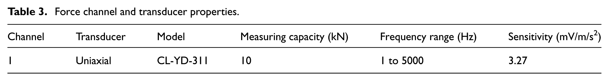
The input–output signals were collected by data logger ECON_AVANT model MI-7016. The accelerometers, shaker, and the transducer specifications are presented in Tables 2–4 respectively. Figure 5(b) shows all the test instruments.
Response channel and accelerometer properties.

Force channel and transducer properties.
Shaker properties.

Modal testing procedure
FRF describes the dynamic properties of a system independent of the signal type used for the excitation. This means that the choice of signal type for the input is free and can be optimized for the instrumentation and the structure under test. 21 Modal testing is non-destructive, quick, and easy tool to find out the dynamic characteristics of a system. 22 The dynamic characteristics of a structure represent material properties (mass, damping, and stiffness) of that structure and any variation of these properties leads to new dynamic characteristics. 23 FRF is defined as the ratio between the response and force in frequency domain. Peaks of FRF represent resonances of the system. For an SDOF system, the FRF has only one peak.
Therefore, the dynamic characteristics (modal parameters) of ballast as a component of ballasted tracks vary with variation of the material properties of ballast. There are many methods to identify modal parameters of systems, and all of them have been offered for linear time invariant (LTI) systems.
System linearity and invariability control
For complex systems such as ballast, it should be considered that the linearity is significantly conditional and it should be checked by coherence function between force and response. In order to check the system linearity, coherence function between force signal and vertical acceleration signal was calculated and is illustrated in Figure 6(a). The convergence of results to 1 confirms the linearity of the system. In order to check the time invariability of the system, the modal tests were repeated many times for one setup. As shown in Figure 6(b), the obtained results of repeated tests are fairly equal. Therefore, evidence supports that the system behaves as an LTI system and modal test and modal analysis are appropriate for evaluating the stiffness and damping of the examined material.

FRF of repeated tests and coherence function: (a) Test 1’s coherence between force and vertical and (b) Test 1’s FRF from four repeated tests acceleration.
Loading pattern and frequency
Of the most important points in modal tests is the ability of input force in exciting the system properly. This means that the amplitude of input force should be strong enough so that available sensors are able to record corresponding responses and it should be weak enough to avoid noise or disturbance in object structure. Moreover, from modal analysis theory, it is known that damping is an inherent characteristic of a system that decreases the ratio of response to force especially at frequencies near the modal frequencies of the system. Therefore, in order to see effects of damping on the system vibrations, the system has to be excited at frequencies near its modal frequencies or to be freely vibrated. 21 Moreover, since train running speed varies from place to place and it causes different loading frequencies, it is important to study the dynamic behavior of ballast and mixture of ballast and TDA under various frequencies, so FRF of the system should be extracted for an applied range of frequencies.
Different ballast conditions along the track and the complex forces imposed by trains passage causes a difficulty to analyzing the dynamic behavior of ballast mixed with TDA in field condition. So, the present study is allocated to laboratory investigating of this material to provide reliable results. Accordingly, the experimental results can be extended to real track system. 24
In this study, various kinds of forces were applied by means of the shaker including Burst random, Chirp sine, and Sweep sine. Figure 7(a) and (b) shows that the Sweep sine method gives a comparatively smooth spectrum and also, as the system becomes stiffer (less percentages of TDA), the fast excitation methods seem to be applicable especially at high frequencies (beyond 100 Hz). There are two important reasons for this observation. First, stiffer systems can respond better to the fast excitation and the Sweep sine provides sufficient time for the system to vibrate with the applied frequencies of shaker. Second, to avoid hitting the plate by the shaker tip, the amplitude of input force was controlled at different frequencies by means of the amplifier’s gain during the excitation; the force amplitude was manually controlled by increasing it at low frequencies and decreasing it at higher frequencies. A threshold for changing the force amplitude (when the shaker starts hitting) is different for every system and depends on its dynamic characteristics. For example, in this case, it happened around 120 Hz for different percentages of TDA.

Results of different excitations: (a) for Test 1 and (b) for Test 4.
In all the tests, Sweep sine was started from 10 to 500 Hz. The load plate was rigid enough to avoid rotational response at the point where the shaker tip was attached; therefore, there was no need to use a stringer. 21 It should be noted that during the tests, a rubber mat was installed in shaker’s support to avoid eventual input noise. Also preloading made a better condition to avoid input noise due to beating of shaker tip on the load plate.
Figure 8(a) and (b) shows all the driving point FRFs. It should be noted that at low frequencies (lower than 20 Hz), excitation of the test materials needs larger force than the capacity of the test shaker. Therefore, at these frequencies, the correlation between force and response is not strong and this factor causes the FRFs to be noisy at low frequencies. Also, at frequencies higher than 500 Hz, the FRF curves are noisy, because of the frequency range of shaker force (from 0 to 500 Hz). Vibrations of the test materials at frequencies higher than 500 Hz are not due to shaker force. So there is no correlation between force and response at these frequencies too.

Amplitude and phase leads: (a) amplitude of driving point accelerance FRFs and (b) phase lead of driving point FRFs.
Both force transducer and accelerometer are mounted in the same axis while their positive directions are opposite. Therefore, it caused extra 180° difference between phases of input and output of system. As mentioned above, the phase lead of accelerance varies from 0 to −3.14 rad, instead of 3.14 to 0 rad.
Cross point FRFs
Utilizing cross point FRF is a suitable method to assure energy distribution in a vibrating test object. Figure 9(a)–(d) show the driving point and cross point FRFs of all the tests calculated by dividing the response of the horizontal accelerometers to the force applied on the top of the system. As mentioned before, the linear relationship between force and response in the frequency range of interest (especially near resonance) proves the accuracy of modal test. Coherence function is a useful tool to show this accuracy. Figure 9(e) shows the coherence functions of horizontal accelerometers in Test 1. These figures show fairly linear relationship between force and response. Particularly, at excitation frequencies near natural frequency of the system resonance happens and whole the test box vibrates strongly. Therefore, it can be said that the two horizontal accelerometers that are installed at distance from each other give useful information about vibration reduction of the material in depth. Thus, the cross point FRFs of Figure 9(a)–(d) are only reliable for the frequency band around the resonance. As depicted in all these figures, due to viscoelastic effect of TDA, as the TDA percentage increases, amplitude of cross point FRFs decreases and the difference between driving point FRFs and cross point FRFs increases. Also, the calculated coherence function from top horizontal accelerometer is more near to one than the coherence function of the lower horizontal accelerometer (Figure 9(e)) that confirms the reduction of vibrations in the height of the box.

Driving point and cross point accelerance FRFs of each test: (a) Test 1, (b) Test 2, (c) Test 3, (d) Test 4, and (e) coherence function between force signal and horizontal accelerations in Test 1.
For better understanding about the material behavior, velocity to force FRF (mobility) and motion to force FRF (receptance) of the four systems were calculated by integrating the measured FRFs shown in Figure 10(a) and (b). These two figures show receptance and mobility of the system for the four tests. It is known that the gradient of initial slope of a mobility is proportional with reciprocal of the stiffness and the initial line of receptance curve, known as stiffness line, is proportional with reciprocal of stiffness. Therefore, as the system going softer, initial line of receptance rises (Figure 10(a)) and increasing of the gradient after adding TDA, indicates that the system is going softer (Figure 10(b)).

Driving point receptance and mobility: (a) amplitude of driving point receptance FRFs and (b) amplitude of driving point mobility FRFs.
Modal system identification
In order to identify the key parameters of the system dynamics such as stiffness and damping, in this section the dynamic terminology of an SDOF system is utilized. In this matter, the rigid plate is assumed as rigid foundation resting on a viscoelastic material. The viscoelastic performance of the mixture of ballast and TDA is due to the viscoelastic behavior of rubber which causes lower deflections under dynamic loads (lower FRF amplitude). 21 This approach has already been used in the field of railway engineering by many researchers. For instance, S Kaewunruen and Remennikov have applied modal testing to determine the dynamic stiffness and damping parameters of rail pads of various ages to investigate their degree of degradation with time in service on rail pad. They assumed a simple mass–spring–damper SDOF system with mass of rail and damper–spring of rail pad. 25 De Man 26 also have applied modal testing and analysis of pad with SDOF method.
In the assumed SDOF model for the explanation of conducted modal test results in this study, the constant mass belongs to rigid loading plate and the spring–damper coefficients come from the mixture of ballast and TDA. It can be observed that by adding TDA to ballast, the system has a softer spring and higher damping. The softening of the system causes shifting of modal frequency to lower frequencies, while the increase of damping of the system leads to the decrease of amplitude of the FRF.
The SDOF accelerance FRF for viscous damping and hysteretic damping can be defined as follows 21

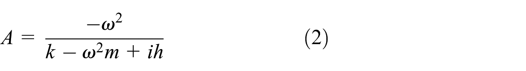

where A is the accelerance FRF, m is the mass of the plate, k is the stiffness, and c and h are the damping constants for viscous and hysteretic damping of the materials, respectively.
Results evaluation
As shown in Figure 8(a), after adding TDA to ballast, the amplitude of dynamic response of the system decreases (viscoelastic behavior of rubber) and FRF’s peaks shift to lower frequencies (neglecting mass variation, lower static stiffness leads to lower natural frequency). Also because of damping effect of TDA, gradient of phase curve decreases.
Since only the frequency bands of Sweep sine excitation were analyzed, all the modal identifications were done on truncated FRFs. The measured accelerance FRFs were modeled by an SDOF mass–spring–damper model generated with a simple method in three steps. First, natural frequency of each test was determined approximately by general peaks of Figure 8(a). Second, by knowing the natural frequency, spring stiffness was determined by equation (3). Third, damping was determined by minimizing the difference between analytical model (equation (3)) and the measured accelerance. Figure 11(a) and (b) shows all the truncated FRFs and corresponding generated models calculated from the truncated FRFs. The identified modal parameters are listed in Table 5. The results show that in Test 2, damping of the system has increased to approximately two times the damping of pure ballast, and stiffness of the system has decreased to approximately half of stiffness of pure ballast. This effect is not proportional to the amount of used TDA, because adding more TDA (Test 3 and Test 4) affects the stiffness parameter more than the damping of the system.

Amplitude and phase leads for various models: (a) amplitude of generated FRFs and (b) phase lead of generated FRFs (the thick lines are hysteretic models and the dashed lines are viscous models).
Results of SDOF modeling.
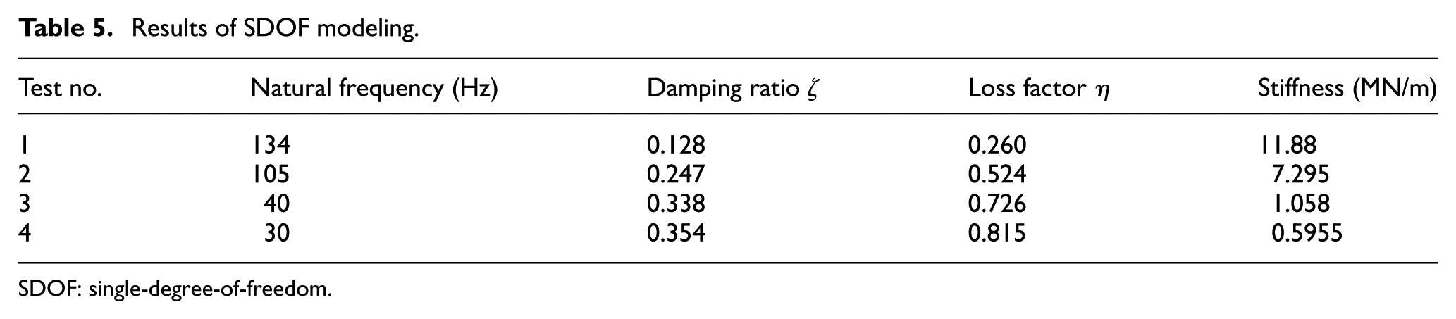
SDOF: single-degree-of-freedom.
Since the mass of the plate is considered as the mass of the SDOF model and the generated FRFs match the experimental FRFs, the assumption of an SDOF model with constant mass of the plate with variable spring–damper of the material seems correct. In order to estimate an optimum percentage of TDA, stiffness curve and loss factor curve are plotted simultaneously and their intersection point is considered as an optimum percentage of TDA (Figure 12). The value is around 10%.
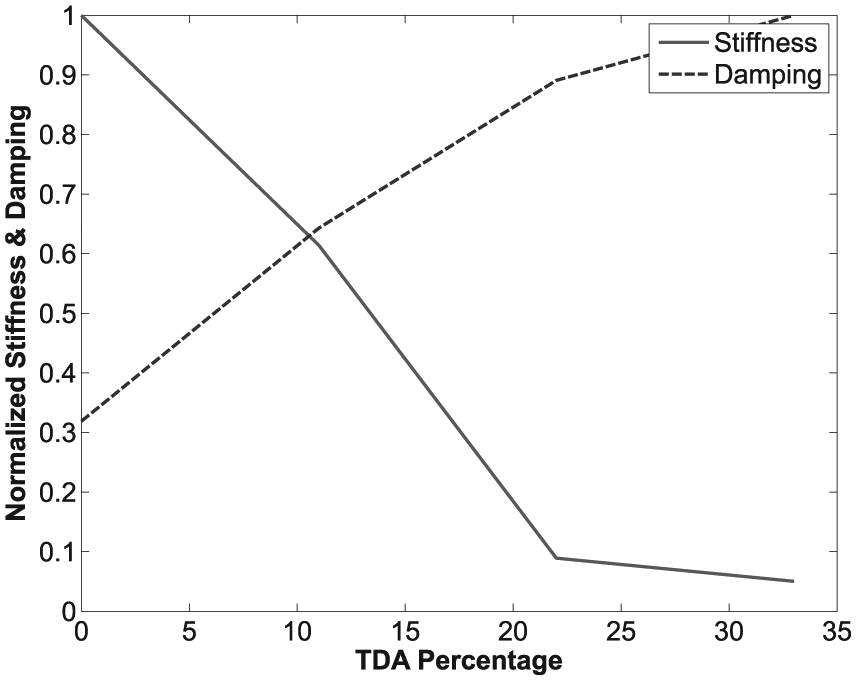
Normalized stiffness and damping versus percentage of TDA.
According to the results of the present laboratory tests, a preliminary optimum percentage of TDA can be suggested for practical use in ballasted track considering the following points:
It should be considered that in the case of mixing ballast with TDA in ballasted railway track located in desert area with potential of sand dune movement, the proposed mixture may cause some short-term decay in track vertical and lateral stiffness or produce some undesirable effects in track operation, but this issue will be obviated by time passing and filling the ballast voids with sand. In this situation, the balanced track resiliency can remove the relevant problems to track rigidity such as ballast and sleeper breakage, additional stresses and impacts on rail and rail pad, and undesirable impacts on rolling stock system. In order to make a final decision on optimum percentage of TDA in ballast, a series of field tests should be planned in desert area under actual operational condition. Having such a test track, the effect of TDA on lateral and vertical stiffness reduction before and after ballast filling with sand can be measured. Moreover, via measuring the vertical accelerations in rail, sleeper, and passing train, the efficiency of the proposed mixture in reducing the vibration can be assessed.
In the case of using the ballast mixed with TDA in railway bridge or railway tunnel as a solution for transition zone, the relevant field measurement should be done to determine the optimum percentage of TDA. Basically, it seems that due to acceptable damping of the proposed material, this idea can be considered as a competitive option with respect to USP and UBM for attenuating the train induced vibrations.
The effect of TDA on reducing the ballast breakage and abrasion under operational loads and during the tamping procedure is undeniable. This means that during the ballasted track operation, interaction of ballast particles with TDA can considerably decrease the ballast rupture and wear. On the other hand, during tamping process, TDA can diminish ballast breakage and abrasion caused by tamping tines or scraper fingers of ballast cleaner machine. In this regard, many abrasion tests such as Los Angeles test, Mill and Micro-Deval tests should be conducted on various mixtures of ballast and TDA to determine the value of decrease in ballast abrasion and breakage. In addition, the breakage of mixture of ballast and TDA under monotonic loads of passing trains can be simulated in ballast box test.
In overall, investigating all aspects of TDA effects on ballast performance need a comprehensive field and laboratory studies. These studies have been planned by the present research team, and its results will be published progressively in future. In this matter, the current study can be assumed as an initiation stage.
Conclusion
To study the effect of TDA on the dynamic characteristics of ballast, the mixture of ballast with various percentages of TDA was experimented by shaker modal test in a loading chamber. At the first stage, the linearity and time invariability of the system were checked and its results were analyzed by parametric and non-parametric methods. Different kinds of excitations were applied and the results showed inefficiency of fast excitation methods such as Burst random and Chirp sine for ballast modal testing. The experimental results showed that after adding TDA, the dynamic response of the system was decreased and resonance frequencies were shifted to lower frequencies. After adding 11% TDA (Test 2), damping of the system was increased to approximately two times the damping of pure ballast and stiffness of the system was decreased to approximately a second of initial stiffness. Adding more TDA (Test 3 and Test 4) affects the stiffness parameter more than the damping of the system. The obtained results in the present study proposes an optimum value of TDA for practical uses. But, in order to prove the real performance of the TDA mixed with ballast in railway tracks an extensive laboratory and field tests is required.
Footnotes
Academic Editor: Crinela Pislaru
Declaration of conflicting interests
The author(s) declared no potential conflicts of interest with respect to the research, authorship, and/or publication of this article.
Funding
The author(s) received no financial support for the research, authorship, and/or publication of this article.