
Abstract
Recently, research on the behavior of nuclear fuel rods in accident situations was performed. The research conducted was very sophisticated and involved complex tasks related to thermal, elastic, plastic, and creep phenomena. Previously, a nonlinear iterative static analysis for the behavior of a nuclear fuel rod was performed taking into consideration the thermal, elastic, plastic, and creep effects. However, the analysis cannot be applied to an unstable situation such as a bulging phenomenon of a nuclear fuel rod when a loss of coolant accident occurs. In this study, a nonlinear iterative dynamic analysis is performed considering large strain and thermo-mechanical effects, and the results of this dynamic analysis were obtained. The analysis is similar to those of static analysis; however, it differs from the static analysis after loss of coolant accident because of the inertia term of the dynamic equation.
Keywords
Introduction
Energy consumption of human beings is drastically increasing till date and will increase further more in the future. The fossil energy will cease to serve sooner or later, and the alternative energy is still far less than the necessity. As the importance of nuclear energy is expected to be increased more and more, the safe control of a nuclear power system including more precise prediction of the accidental behavior of nuclear fuels is required because of the formidable situation that would be encountered in case of an accident, which might happen without warning. Recently, researches on the behavior of nuclear fuel rods in accidents are being performed; the research conducted are very sophisticated and involved complex task related to thermal, elastic, plastic, and creep phenomena. Moreover, the strain may not be small; thus, we need a large strain plasticity analysis.
Thermo–elastic–plastic–creep analysis was fully developed using an equivalent stress function algorithm for small strain problems. 1 Large strain plasticity analyses were studied for isotropic and anisotropic problems.2,3 Thermo–elastic–plastic–creep analysis considering large strain plasticity has been applied to nuclear fuel in loss of coolant accident (LOCA) situation. 4 However, the quasi-static analysis could not handle the bulging phenomenon at the final stage of deformation.
The bulging phenomenon is a type of stability problem, and neither the quasi-static approach nor the post-buckling approach can be used to deal with this phenomenon, as these approaches are not suitable for problems where properties depend upon time and temperature. The only appropriate approach is a dynamic analysis considering the thermo–elastic–plastic–creep effects. This dynamic analysis will be developed and applied to the LOCA situation to show the thermo-mechanical behavior of fuels at the final stage of deformation. The results will show the exact time when the nuclear fuel rods will fail in a LOCA situation after the bulging phenomenon, which is a critical factor in the design and recovery of nuclear power plants.
Finite element analysis of nuclear fuels including the bulging phenomena
For the analysis of the bulging phenomenon of a nuclear fuel rod, the heat transfer equation and the dynamic equation of motion will be presented. However, when the inertia term is neglected, the dynamic equation may be reduced to an equilibrium equation.
Nonlinear transient heat transfer equation
For the thermo–elastic–plastic–creep analysis of a nuclear fuel rod, it is necessary to obtain time-dependent temperatures by solving the following well-known transient equation of heat transfer


where T is the temperature, k is the coefficient of the thermal conductivity, ρ is the density, c is the specific heat, q is the heat flow rate, f B is the heat flux, and h is the convective heat transfer coefficient. The partial differential equation of heat transfer (equation (1)) is expressed in other functional forms to be minimized as in equation (2). 5
Consider

where

Superscript i indicates the quantity of iterative state i at time
Iterative nonlinear equation of motion
After obtaining the temperature distributions of the fuel, the incremental equilibrium equation for the motion of the fuel can be solved to obtain the incremental displacements. Generally, the method for analyzing nonlinear problems includes the total Lagrangian and updated Lagrangian formulation. The updated Lagrangian formulation, which calculates the state at time
The principle of virtual work at time t may be expressed as

where
The relation between the external virtual work

Applying the quotient law in order to obtain the equivalent nodal forces from equation (6)
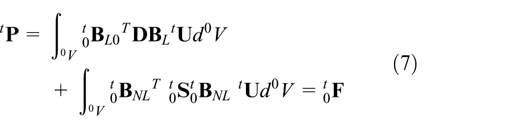
where
Because it establishes the equilibrium state when the external force is equal to the equivalent nodal force at time

Equation (8) can be written in the increment form as

where


is obtained, and because the inertia force is added to body force, in dynamic problems, equation (11) can be written as

where

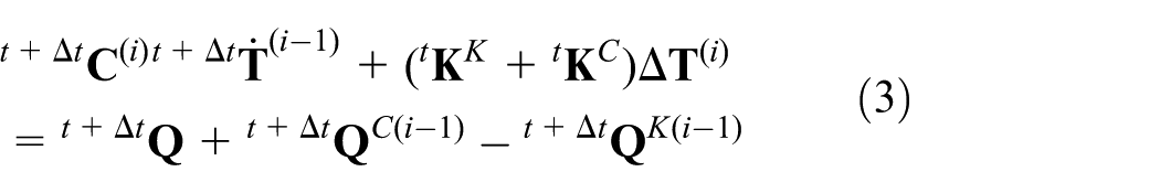
As equations (11) and (12) are linearized equations, they have some errors in comparison to the exact solutions. Therefore, iteration is required to correct the errors. Equation (12) can be expressed with the equilibrium by the Newton–Raphson iteration and Newmark method as follows 6

Superscript i indicates the quantity of iterative state i. In order to simplify the displacement, equation (14) can be written as equation (15)

As an iterative equilibrium equation which combines the Newton–Raphson iteration method and the Newmark integration method is used in the numerical calculation, equation (14) analyzes the nonlinear dynamic problems in this article. Ignoring the mass term in equation (15), the nonlinear incremental equilibrium equation for the quasi-static motion of the fuel can be obtained.
Thermo–elastic–plastic–creep analysis
The deviatoric stress is computed from the deviatoric strain while regarding the plastic and creep strain1,4 adopting the same symbols in Kojic and Bathe 1 as

The mean stress is computed from the mechanical mean strain as equation (17)

where
If we split the plastic and creep stains at

where

where
Creep strain may be represented by various creep laws such as the power creep law or the exponential creep law. To confirm plastic stress based on the given displacement,

where


We have to solve the equation to obtain the deviatoric stress tensor. By applying following flow rules of plastic and creep deformations


where
We obtain

where

Taking the product of both sides of the equation, we obtain the following equation

where
The function on the left side of equation (28) is known as the effective-stress function, and it has to satisfy the condition of zero. Because
Here, we propose a first stage constitutive modulus as
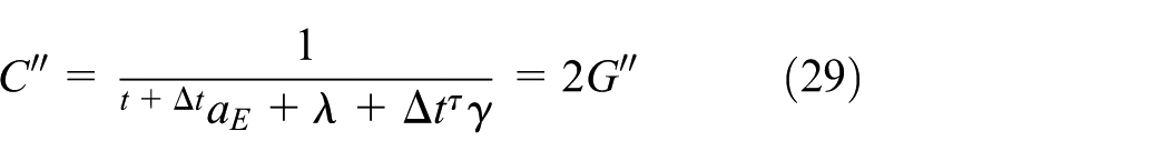
where
Large strain (Hencky logarithmic) measure
For large strain analysis, some basic relations are required which are briefly introduced here.2,3,8–11 The deformation gradient is represented by

where

The right Cauchy–Green gradients are expressed using the deformation gradient

Solving the following equivalent problem

A diagonal matrix

Therefore, the rotation matrix is given by

Then, the Hencky logarithmic strain tensor is given by

where

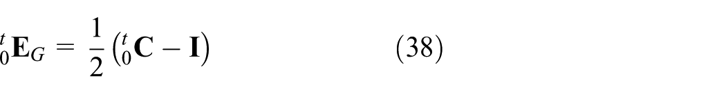
The Green–Lagrange strain tensor can be represented as
and the Almansi strain tensor as

The Hencky logarithmic strain tensor can also be written as
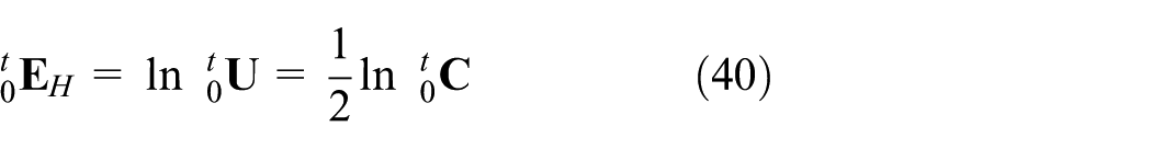
Using the equations above and comparing them (three kinds of marks) with theoretical equations (equations (41)–(44)) in Figure 1 then
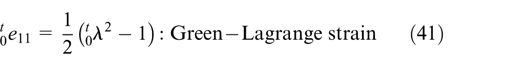


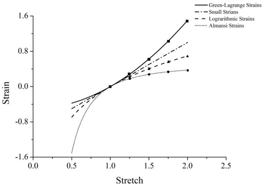
Strain–stretch relations for various strain measures.
Using the procedure of thermo–elastic–plastic–creep with logarithmic strain measure and additive decomposition of plastic strain, the developed Fortran program with additive decomposition method follows the procedures in Bathe and colleagues,2,8,9 except that plastic deformation gradient is not decomposed multiplicatively as

at the trial elastic state first, but considered additively as in equations (16) and (18). Therefore, continuation between later large strain procedure and former small strain procedure including creep deformation is not lost.
Verification of developed program
For the analysis of the bulging phenomenon of a nuclear fuel rod, analysis program is developed. The developed FORTRAN program was tested with several cases.
Thermal analysis
Thermal analysis 4 was performed using the present program and commercial package ADINA. The boundary conditions are shown in Figure 2.

Boundary condition for thermal analysis.
Temperatures are analyzed and the results of three nodes are compared in Table 1 showing a good agreement.
Results of thermal analysis.

Plasticity analysis
Plasticity analysis 4 was performed using the present program and commercial package ADINA. The boundary conditions are shown in Figure 3.

Boundary condition for plasticity analysis.
The von Mises, radial, and hoop stresses are analyzed for three cases of perfect, bilinear, and general plasticities. The initial value of the yield stress is 25 MPa, and the mechanical pressure load increases up to 9 MPa with 90 steps. As shown in Figure 4, the present program is proven to have a verified accuracy for the plasticity problems.

Results of plasticity analysis: (a) perfect plasticity, (b) bilinear plasticity, and (c) general plasticity.
Creep analysis
Creep analysis was performed using the present program and commercial package ADINA. 4 The boundary conditions are shown in Figure 5.

Boundary condition for creep analysis.
The von Mises, radial, and hoop stresses of the present program and ADINA are compared each other for creep problems as shown in Figure 6. The present program is reliable in the analysis of elasto-creep as well as in the thermal and plasticity analyses.
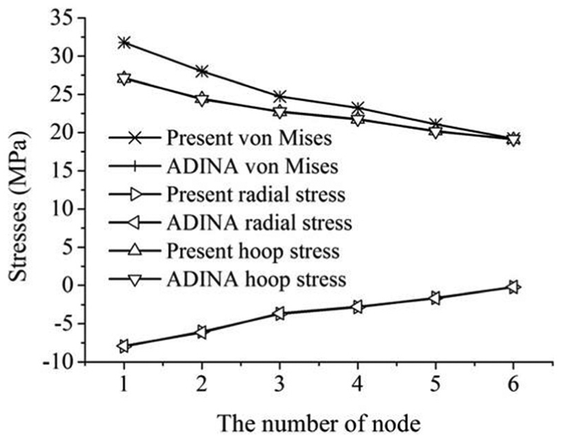
Results of creep analysis.
Large strain plasticity
For the case without creep deformation, the following example compares the two procedures of large strain problems: additive decomposition (developed present program) and multiplicative decomposition. 2 The first one is uniaxial isochoric extension with the following conditions
An in-plane isochoric deformation with no rotation of the principal stretch directions, given by the deformation gradient

where λ ∈ [1, 1.5].
The results are compared in Figure 7 showing a good agreement.

Normal stress σx along stretch λ.
The second example is shear deformation given by the deformation gradient

where γ ∈ [0, 0.5].
The result compared to the literature results (solid square) obtained by the multiplicative decomposition 2 in Figure 8.

Shear stress τ12 along shear strain γ.
Behavior of nuclear fuel rods after LOCAs considering the bulging effect
After a LOCA during the behavior of nuclear fuels, an unstable situation develops where the cladding stiffness becomes zero because of a local uncontrollable deformation. 4 In this case, an analysis using the post-buckling method applied to quasi-static problems is not a proper method for analyzing this transient problem because properties of the materials, which composed the nuclear fuel rods, are not constant. The material properties are considered functions of time and temperature. In order to analyze this type of phenomenon without divergence, the dynamic analysis method was adopted. Consequently, the bulging motion of the inflated nuclear fuel rods during a LOCA situation can be analyzed using the dynamic equation.
In the usual case of LOCA, the control rods are inserted into the fuel rods to shut down the reactor, and the power is reduced successfully. However, during events, such as the Fukushima accident, the control rods could not be inserted into the fuel rods because the insertion system, which is located at the lower part of the reactor, is malfunctioned. Therefore, it was assumed that the heat generation of the fuels was partly reduced.
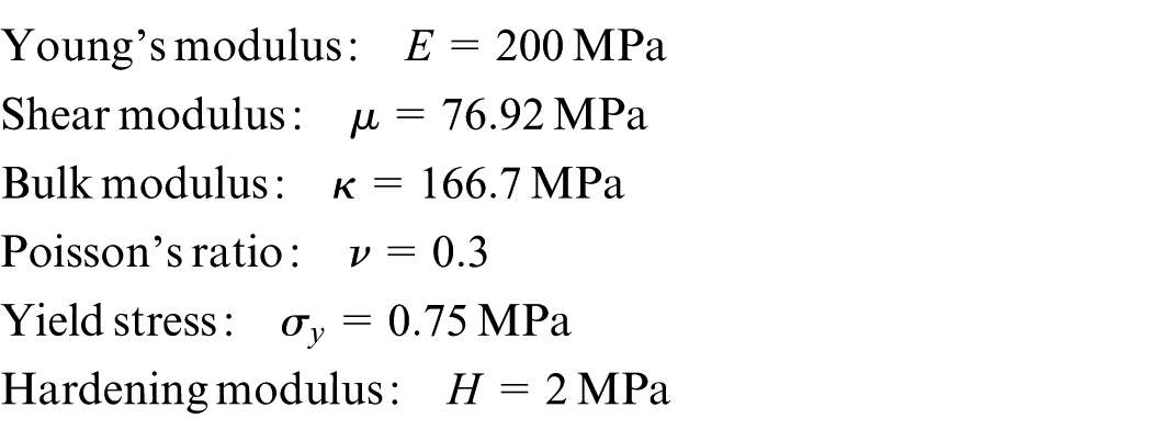
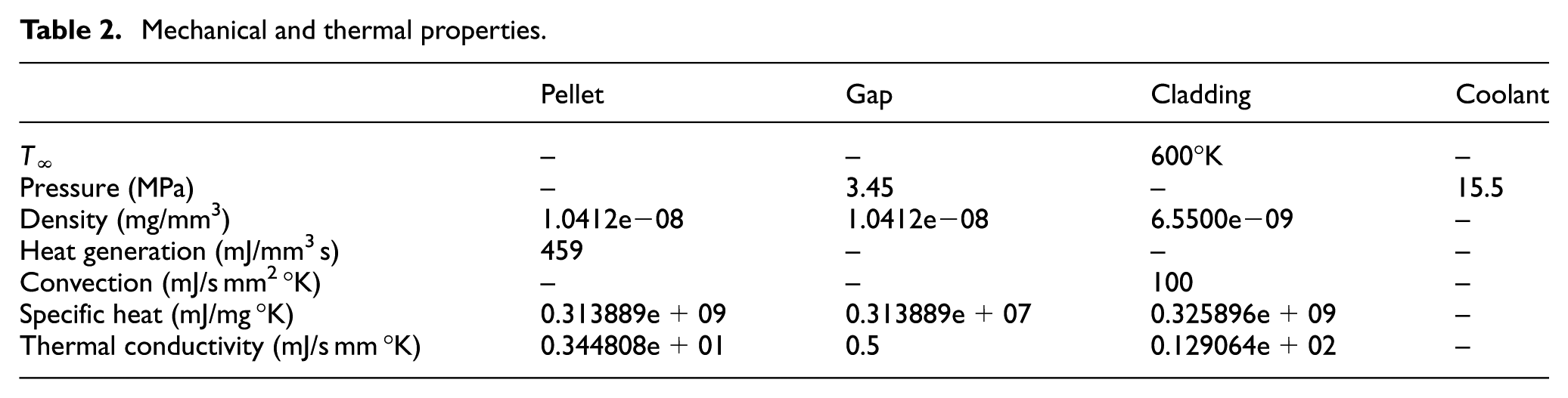
The material properties of the fuel components are the same as in the literature.12,13 Mesh generation of the fuel rod was conducted using two-dimensional (2D) axisymmetric and quadrilateral eight-node elements, and the boundary conditions were applied as shown in Figure 9. The boundary conditions include the application of heat generation to the pellet as well as coolant pressure and convection heat transfer from the cladding to coolant. In addition, the gas pressure of the gap between the pellet and the cladding is also applied. The actual nuclear fuel rods are activated with mechanical and thermal properties shown in Table 2. In this article, the gas pressure of 34.5 MPa is applied to the analyses to assume the severe situation of the nuclear fuel rods. Figure 10 shows the temperature changes at the pellet center and cladding outer surface at steady-state conditions prior to 100 s.

(a) Solid nuclear fuel model and (b) boundary conditions.
Mechanical and thermal properties.
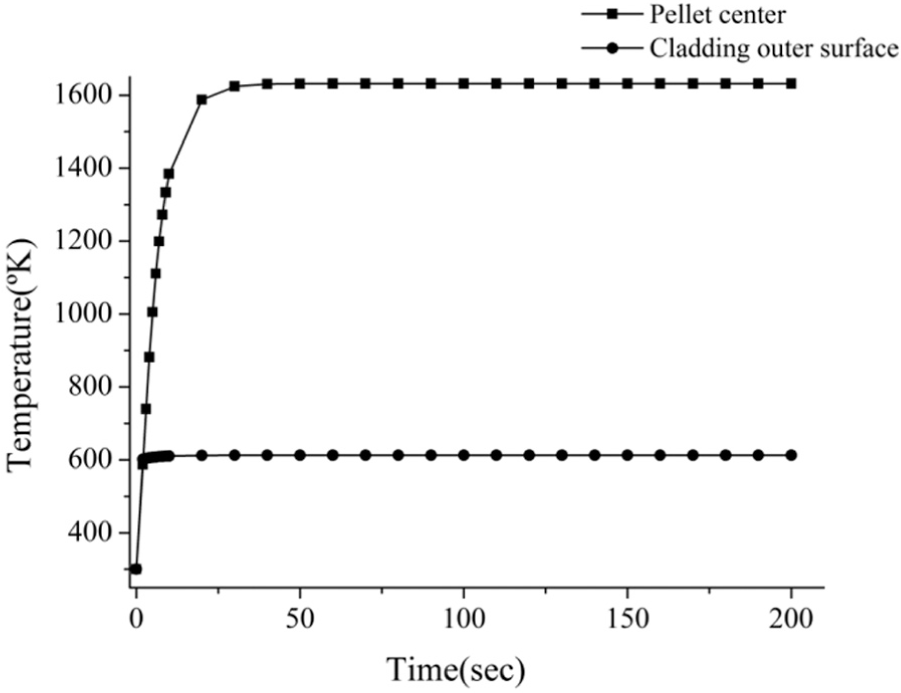
Temperatures changes at pellet center and cladding outer surface along time. 4
The LOCA event was assumed to occur at 70 s resulting in a loss of coolant pressure and change in the ambient heat transfer coefficient from 7500 to 75 mJ/s mm2 °K. In addition, the control rod is also malfunctioned. It was assumed that one of four conditions of heat generation (complete shutdown = 0%, 55%, 60% and full heat generation = 100%) was maintained after LOCA. Temperature changes at the cladding outer surface are shown in Figure 11. As expected, there were rapid changes in temperature at both the outer surface of the cladding because of the shutdown. It was detected that the outer surface of the cladding shows a rapid increase in temperature and then the temperature increases slowly afterward at both 60% and 100% while temperature of the reactor continued to decrease at complete shutdown after 70 s. After LOCA, there were sharp increases in temperature especially for full heat generation. The cladding withstood the internal pressure load from the fuel rod. However, Young’s modulus and strength of the clad decreased since the cladding temperature beyond the steady-state temperature condition of 600 °K. As a result, the fuel rod cannot resist the pressure load and deformation begins to occur, which causes larger stresses leading to fuel failure. This phenomenon is similar to buckling instability. The asterisk marks denote the divergence time at each heat generation in the quasi-static analysis of the fuel rods.

Temperatures at cladding outer surface with the LOCA at 70 s.
Figure 12 shows the radial displacements of the cladding outer surface during operation with considering dynamic effects. The heat generation above 55% reactor power caused cladding instability, which then induced continuous expansion of the fuel rod ultimately leading to burst fuel rods. However, adopting the dynamic equation, the analyses was not been stopped due to the instability conditions. The variations of hoop stresses at the cladding surface are shown in Figure 13.

Radial displacements of cladding outer surface with the LOCA at 70 s.

Hoop stresses at cladding outer surface with the LOCA at 70 s.
In the case of 60% and 100% heat generation after a LOCA, the behavior of the fuel rods could be analyzed using the dynamic equation without considering the cladding instability. This approach differed from Kim et al. 4 where the analyses do not consider the dynamic effects.
Conclusion
For the safe design and operation of a nuclear power plant, a precise thermo-mechanical analysis regarding the behavior of nuclear fuel rods in accidental situations is required as well as the analysis for controlled operations. Thermo-mechanical analysis, including the thermal, elastic, plastic (large strain), and creep effect, on nuclear fuel comprehensively is rare. Moreover, the bulging phenomenon, which is the last stage of deformation followed by the bursting failure, cannot be analyzed by a conventional quasi-static approach. We presented a nonlinear dynamic analysis of nuclear fuel rods considering the thermal, elastic, plastic (large strain), and creep effects for analyzing the bulging phenomenon in LOCA cases. It can be summarized as follows:
A comprehensive nonlinear iterative static analysis of nuclear fuel rods was made including the thermal, elastic, large strain plastic, and creep effects.
A nonlinear iterative dynamic analysis procedure was formulated including the thermo-mechanical effects to handle the bulging phenomenon in LOCA situation.
The results of the dynamic analysis are very close to those of the static approach before the bulging. During the bulging phenomenon, dynamic results could be obtained while static analysis failed to proceed beyond the critical point.
Footnotes
Academic Editor: Nao-Aki Noda
Declaration of conflicting interests
The author(s) declared no potential conflicts of interest with respect to the research, authorship, and/or publication of this article.
Funding
The author(s) disclosed receipt of the following financial support for the research, authorship, and/or publication of this article: This research was supported by the Basic Science Research Program through the National Research Foundation of Korea funded by the Ministry of Education (NRF-2012R1A1A2008903). The authors are partially supported by the BK21 PLUS project of the Korean Research Foundation.