
Abstract
An investigation of the abrasive water jet with an emphasis on the oblique impact of abrasive particles on the target plate is performed. Ultra-high jet pressure necessitates a close examination of the phenomena featured by small spatial and temporal scales. The effect of oblique impact is assessed from both numerical and practical aspects. Numerical simulation, implemented using the commercial code LS-DYNA, allows a detailed inspection of transient stress wave propagation inside the target plate. And impact experiments facilitate a qualitative description of resultant footprints of oblique water jet. Different incident angles of abrasive particles are adopted and a comparison is thereby unfolded. The results indicate that rebound, embedding, and penetration of single abrasive particle are three representative final operation states. Adjacent to the abrasive particle, the response of the target plate to oblique impact is reflected by von Mises stress distribution and plate deformation as well. Oblique impact arouses non-symmetrical stress wave distributions and distinct unbalanced node displacements at the two sides of the abrasive particle. As for the target plate, global surface morphology is in accordance with predicted effects. The most favorable surface roughness is not associated with vertical impact, and it hinges upon the selection of standoff distance. Furthermore, variation of surface roughness with incident angle is not monotonous.
Introduction
The versatility of abrasive water jet (AWJ) has been approved in many industrial applications. Meanwhile, technical advancements of commercialized AWJ products, particularly in recent years, have triggered the emergence of complex issues. It should be pointed out in this connection that mechanical and electrical aspects related to AWJ products are well understood, as significantly benefits relevant product design and operation. In comparison, the knowledge of multiphase flow features of AWJ at high and ultra-high jet pressures is far from sufficient. Essentially, fluid dynamics behavior of AWJ directly affects the target work piece and is thus pivotal for resultant processing quality. Furthermore, attention should be paid to the contribution of abrasive particles in view of their evident effect on resultant surface roughness. Although high-pressure liquid drops also can fracture the impacted work piece with high stagnation pressure or water hammer effect, the impact energy is low compared with that carried by abrasive particles. 1
In the AWJ stream, the kinetic energy of abrasive particles stems from ambient water. Hitherto, instantaneous energy transfer between the two mediums has not been clarified. As for this subject, both flow pattern and flow scale deserve an in-depth examination. Even with computational fluid dynamics (CFD), a prevailing approach in the investigation of solid–liquid two-phase turbulent flows, an unambiguous description of this inter-phase interaction is difficult to accomplish. The root cause is the difficulty in the treatment of tiny jet streams with exceedingly high jet velocity magnitudes. Numerical problems are further complicated by the conjecture that rebounding, embedding, and breaking of abrasive particles occur during the impact process. 2 Meanwhile, numerical efforts have been dedicated to the improvement of numerical scheme suitability such as the assumption that abrasive particles constitute continuous phase and the employment of coupled smoothed particle hydrodynamics with finite element method (FEM).3,4 Nevertheless, efforts devoted to numerical simulation of solid–liquid two-phase flows have been guided toward the pursuit of averaged parameters such as erosion rate. 5
Reported experimental work associated with AWJ is overwhelmingly concerned with vertical impact. Figure 1 exhibits typical footprints left on two cut sections, which result from vertical impact of AWJ at the jet pressure of 200 MPa. Materials involved in Figure 1(a) and (b) are different, thus two traverse speeds, 200 and 260 mm/min, were used, respectively, along with the same standoff distance of 3.0 mm. The two subfigures share analogous streak patterns, namely, away from the nozzle, streaks are not parallel to vertical jet direction. Local surface roughness is thereby increased. Such an adverse situation is anticipated to be alleviated with oblique impact. The rationale lies in the intensified interference of incidence direction of abrasive particles and the traverse direction of the nozzle. Oblique impact on API X42 samples has been attempted and the solid particle velocity was lower than 81 m/s. 6 Incidence angles of 30° and 60° have been studied with 25-µm alumina particles at 6.1 MPa. 7 These two cases typify the low jet pressure oblique impact. As for high and ultra-high jet pressure cases, the literature has been scarce. The parameter of erosion rate was utilized to assess the oblique impact effect. And the calculation of this parameter necessitated a synthetic consideration of impingement time, particle size, and particle concentration. 8 Additionally, numerical simulation of oblique impact has been conducted with an emphasis placed upon the temperature distribution in the abrasive particles. 9

Images of resultant sections cut by vertical AWJ: (a) Al alloy and (b) Cu alloy.
In this study, the oblique impact of AWJ at ultra-high jet pressure is specifically studied. In view of the suitability of FEM in addressing issues of high-velocity penetration, instantaneous oblique impact of the abrasive particle is expected to be simulated with such a method. 10 And numerical work is performed using the commercial code LS-DYNA. Multiphase flow aspects are beyond the scope of this study. Therefore, the initial velocity of the abrasive particle is determined according to existing formulae. Apart from the evolution of stress distribution, displacements of critical nodes adjacent to the abrasive particle are also extracted from the numerical results. As a further step, experiments are conducted to evaluate the global impact effect of AWJ at jet pressure of 320 MPa. Resultant cut sections are observed with scanning electron microscopy (SEM), and surface roughness is qualitatively examined using a confocal microscope. In both numerical and experimental works, comparison is carried out between oblique and vertical impacts to yield an unbiased description of oblique impact. This study is intended to explain small spatial and temporal features of oblique AWJ impact and the mechanism underlying such an impact scheme.
Numerical methodology
Initial velocity of the abrasive particle is pivotal for consequent stress distribution in the target work piece. So far, the flow simulation of ultra-high pressure AWJ still endures debates in fidelity of turbulence model, boundary conditions, and even grid number. 11 In this case, abrasive particle velocity has to be defined otherwise. This velocity serves as a critical initial condition for subsequent simulation with FEM.12,13 Here, a validated abrasive particle velocity model was used to calculate the initial velocity of the abrasive particle. This model can be expressed through the following formula 14
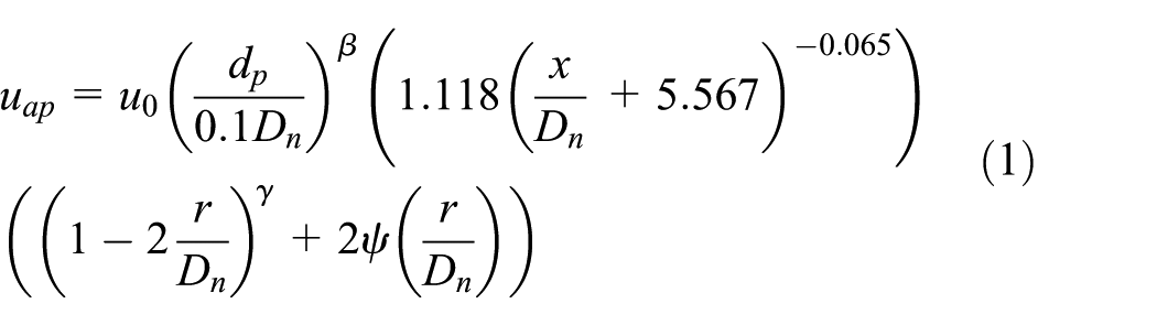
where u0 is the maximum water velocity at nozzle outlet. In view of the small diameter of the nozzle outlet, u0 can be obtained from

where P is the jet pressure with the unit of MPa and the unit of u0 is m/s, dp is the equivalent diameter of the abrasive particle, Dn is the diameter of nozzle outlet section, x denotes standoff distance, r stands for radial distance from the jet axis, and β, γ, and ψ are three coefficients, which are determined by

At the jet pressure P of 320 MPa and the nozzle outlet diameter Dn of 0.8 mm, three abrasive particle velocities, 793, 700, and 410 m/s corresponding to r = 0.0 mm, r = 0.2 mm, and r = 0.4 mm, are obtained. These three radial positions were associated with different magnitudes of abrasive particle kinetic energy and they served as initial conditions in subsequent FEM simulations.
Geometrical models
Irregular shapes of abrasive particles promote the damage of the target work piece. Meanwhile, during the impact process, even in the nozzle passage, breakage of abrasive particles might occur and the effective impact energy is impaired thereby. 15 A consideration of various factors related to abrasive particles in turn elevates the uncertainty of obtained results. 16 It is highly preferable to associate abrasive particles with the impact energy imposed on the target work piece. S Paul proposed a relationship between stress wave energy and two abrasive particle geometrical parameters, namely bluntness and sphericity. He also proved that the augment of the two parameters would entail the increase in stress wave energy. 17 Here, single abrasive particle is utilized to nurture an explicit description of deformation and stress related to oblique impact. The major axis of the abrasive particle is intentionally lengthened to alleviate the lateral resistance from the target plate. 18 Three cases with three different incident angles of the abrasive particle are examined, as shown schematically in Figure 2.
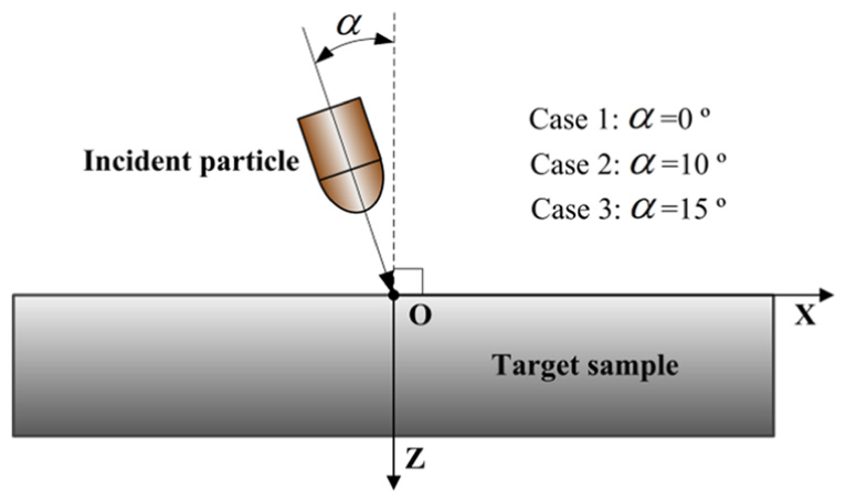
Schematic view of oblique impact with single abrasive particle.
The diameter of the cylindrical part of the abrasive particle is 0.178 mm. Standoff distance, defined as the vertical distance between the front vertex of the particle and the upper boundary of the plate, is 4.0 mm. The material of the abrasive particle is SiC, and the target plate is made of Ti-6Al-4V. And the plate is assumed to be isotropic. The thickness of the target plate is 0.4 mm. In view of the linear relationship between the attainable erosion depth and the kinetic energy required for the abrasive particle, further increase in plate thickness contributes little to the clarification of impact effect. 19
Damage model
Based upon Lagrange method, the commercial code LS-DYNA served as a platform for predicting stress wave propagation and dynamic response of the impacted object to external loads. In the present simulation, the rigid material model is used for the abrasive particle, and the target plate is governed by the Johnson–Cook model. Johnson–Cook constitutive model was proposed in 1983 and this model proves to be highly feasible for cases with large deformation, high strain rate, and high temperature. 20 A modified version of Johnson and Cook’s constitutive relation and failure criterion has been integrated into LS-DYNA. 21 The modified Johnson–Cook constitutive relation, taking into account the evolution of equivalent von Mises stress σ as a function of plastic strain, strain rate, and temperature, is expressed as
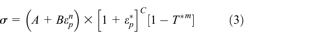
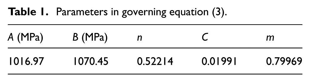
Determined based upon material properties, values of the five constants of A, B, C, n, and m are listed in Table 1.
Parameters in governing equation (3).
And non-dimensional plastic strain rate
where
where T is actual temperature, and the subscripts r and m indicate room and melting temperatures, respectively.
The fracture criterion of Johnson–Cook is expressed by

where
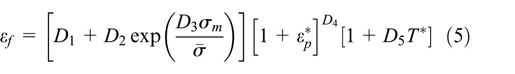
Failure happens as D attains a critical value of 1. And parameters in equation (5) are listed in Table 2.
Parameters in governing equation (5). 22

Computational zones and boundary conditions
Half of the whole computational domain is shown in Figure 3 where the abrasive particle is being ejected with an incident angle of 10°. Structured grids are used to discretize the computational domain. Local areas directly confronting the impact of the abrasive particle is treated with refined grids. Particularly, in X direction, dense grids are remarkable in view of the orientation of the abrasive particle. Such a grid scheme is suitable since parameter variation in those local areas is appreciably drastic. As the target plate is impacted by the abrasive particle, transient propagation of stress wave over the entire computational domain is typical and deserves an in-depth investigation. In line with this principle, the computational domain shown in Figure 3 satisfies full development of stress waves as well as conceivable vertical and horizontal deformations.

Computational domain discretized with structured grids.
Symmetry conditions are defined for the XOZ plane. Rotation of the plate is completely restricted, and as for translational movement, only displacement in Z direction is permitted. Non-reflecting boundary conditions are set for the three side surfaces parallel to Z axis, as enables a simulation of infinitely large target plate. The direction of gravity coincides with positive Z direction. Unsteady computation is performed without initial stress exerted on the computational domain. The time step is set to 0.03 µs, which is determined through examining stress wave propagation between results of two neighboring time steps. Apart from that, the evolution of the footprint left in the plate is also used as a criterion for the suitability of time step value.
Numerical results and discussion
Three final states of the target plate
Practical applications of AWJ have testified four typical eventual states, namely, strengthening of the target material without clear footprints, rebound of abrasive particles accompanied by obvious footprints, embedding of abrasive particles in the target work piece, and full penetration of abrasive particles through the target work piece. The first one occurs at relatively low initial abrasive particle velocity. 23 And the other three are substantiated in Figure 4 where the case of α = 10° serves as a representative. As shown in Figure 4(a), the abrasive particle rebounds after it impacts the target plate, while an apparent pit is left on the impacted surface. The profile of the pit indicates that only the front head of the particle participates in the direct collision between the particle and the plate. And this is ascribed to the low kinetic energy carried by the particle. As the initial abrasive particle velocity increases from 410 to 700 m/s, the abrasive particle enters into the target plate but is finally embedded into the plate due to insufficient impetus, as evidenced in Figure 4(b). At uap = 793 m/s, the abrasive particle travels through the plate, as seen in Figure 4(c). Among the three final states presented, as the severity of damage to the target plate is enhanced, grid deformation associated with the resultant footprint concurrently gets distinct. In this context, the disparity between the cases with single abrasive particle and with multiple abrasive particles is obvious. For the latter, neatly arranged footprints are impossible, and the footprint width varies along the path of penetration. 24

Three resultant states with different initial velocity magnitudes: (a) rebound of the abrasive particle, 410 m/s, (b) embedding of the abrasive particle in the target plate, 700 m/s, and (c) perforation of the target plate by the abrasive particle, 793 m/s.
Propagation of stress wave
At the three high velocities adopted, corresponding impact processes cover exceedingly short periods. Furthermore, these processes cannot be genuinely visualized using available experimental techniques. Numerical simulation makes up such a deficiency and the obtained cross-sectional von Mises stress distributions thereby are shown in Figures 5 and 6 where initial abrasive particle velocities are 410 and 700 m/s, respectively.

Instantaneous von Mises stress distributions at initial abrasive particle velocity of 410 m/s. The three subfigures correspond to the moment when the abrasive particle just rebounds from the target plate: (a) α = 0°, (b) α = 10°, and (c) α = 15°.

Instantaneous von Mises stress distribution at initial abrasive particle velocity of 793 m/s. The three subfigures correspond to the same impact moment: (a) α = 0°, (b) α = 10°, and (c) α = 15°.
As shown in Figure 4, at uap = 410 m/s, the abrasive particle is rebounded from the target plate following the impact, irrespective of the value of α. The three states exhibited in Figure 5 correspond to the same moment of impact. Parallel to the XOY plane, symmetrical distributions of von Mises stress with respect to the abrasive particle are associated with the vertical impact, while the oblique impacts share non-symmetrical stress distributions. In particular, at α = 10°, at the left of the abrasive particle, strikingly high stress is observed. This is in agreement with oblique impingement results documented in Li et al. 25 However, for the case of α = 15°, non-symmetry is evident but stress magnitude is lower than that at α = 10°. Such a phenomenon is in large part attributed to the fact that effective kinetic energy at α = 15° is low compared with that at α = 10°. Thus, the impact at α = 15° is comparatively weak. On the XOZ plane, overall von Mises stress distributions of α = 0° and α = 10° cases are similar. Regarding the case of α = 15°, high von Mises stress tends to pervade a large area relative to the other two cases. Meanwhile, for all the three cases, beneath the resultant pit but still contained in the cone-shape high-stress zone, there exists a low-stress area immediately downstream of the high-stress front. The low-stress area corresponds to a plastic zone demonstrating the mechanism of crater removal which was suggested in Jafar et al. 26 This phenomenon also forecasts a potential damage which might come into effect provided that the high-stress front advances further. Additionally, the stress wave profiles shown in Figure 5 resemble those accompanying cavitation peening. 27 Nevertheless, the deformation caused by cavitation peening is negligible.
At uap = 793 m/s, the abrasive particle can penetrate through the target plate, as applies to all the three cases. Distributions of von Mises stress shown in Figure 6 correspond to the moment that the front head of the abrasive particle is about to pierce through the target plate. At this moment, on the upper surface of the target plate, the three cases share similar stress distributions and the annular high-stress band does not overlap with the edge of the resultant pit. Meanwhile, on the XOZ plane, at each side of the abrasive particle there is a high-stress peak. Furthermore, along the motion direction of the particle, the width of the footprint on XOZ plane keeps nearly invariant. Apart from footprint orientation, the most remarkable difference among the three stress distributions on XOZ plane is the stress unbalance with respect to the abrasive particle. In this connection, comparable studies documented are overwhelmingly related to vertical impact. Both the footprint profiles and stress distributions shown in Figure 6(a) are similar with the results of the penetration of a bullet into an aluminum plate. 28 And stress distributions shown in Figure 6(a) are also in agreement with those obtained with the spherical abrasive particle. 29 It is thereby concluded that the contribution of high abrasive particle velocity is significant at ultra-high jet pressures.
Time history of Z displacement
In Figures 5 and 6, it is observable that computational nodes near the abrasive particle are sensitive to the effect of incidence angle of the abrasive particle. Here, for each case, two nodes along X axis, distributed symmetrically with respect to the abrasive particle, are monitored. And the variation of displacement in Z direction at these nodes is plotted in Figures 7 and 8, which are associated with uap = 410 m/s and uap = 700 m/s, respectively.
Variation of Z displacement at initial abrasive particle velocity of 410 m/s.

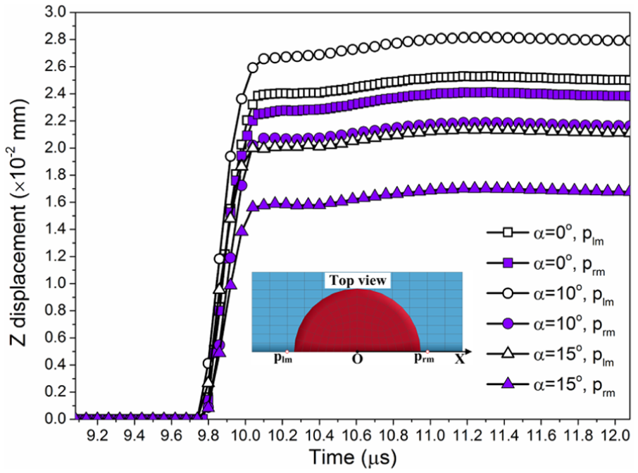
Variation of Z displacement at initial abrasive particle velocity of 700 m/s.
As shown in Figure 7, for each monitored node, a nearly linear increase in Z displacement and the stabilization of Z displacement occur successively. For the case of α = 0°, nodes plm and prm have almost identical variation tendencies and corresponding displacement values. At α = 10°, the gap between nodes plm and prm is remarkable. Relative to vertical impact, the case of α = 10° possesses large node displacement at the left of the abrasive particle and small node displacement at the other side of the abrasive particle. This comparison supports the non-symmetrical properties of oblique impact. However, for the case of α = 15°, Z displacements of nodes plm and prm decline compared with vertical impact results. The reason lies in that the footprint depth at α = 15° is small compared with the other two cases.
The results at uap = 700 m/s are plotted in Figure 8. With respect to each case, Z-displacement values marked in Figure 8 are small compared with their counterparts shown in Figure 7. Apparently, deformation decays with a considerable improvement of the kinetic energy carried by the abrasive particle. Meanwhile, Z displacement in Figure 8 fluctuates obviously before stabilization. These fluctuations happen as the abrasive particle travels inside the target plate. After the abrasive particle entirely leaves the target plate, Z-displacement values tend to be stable. For the case of α = 15°, node displacement at the left node plm is saliently large, as implies that the penetration process is difficult compared with the other two cases. From another perspective, large Z displacement exacerbates resultant processing quality.
Experimental set-up
As for the numerical results discussed above, experimental validation is impractical in terms of releasing single particle at ultra-high jet pressure. 30 But water jet footprints can be obtained with experiments. A water jet cutting device manufactured by Dardi International Corporation of China was used to produce ultra-high pressure AWJ, as shown in Figure 9(a). With this device, the attainable maximum jet pressure is 380 MPa. The jet pressure of 320 MPa was used here, as is in agreement with the numerical work.

Configuration of experimental components: (a) abrasive water jet machine and (b) schematic of the impacted plate.
In the experiments, identical rectangular Ti-6Al-4V plates, 3.0 mm in thickness, 30.0 mm in length, and 40.0 mm in width, acted as target samples. Initial standoff distance was set to 4.0 mm. Oblique impact was realized using different supporting triangle frames below the target plate, while the vertical orientation of the nozzle was kept constant, as shown in Figure 9(b). For the configuration of the nozzle and the target plate shown in Figure 9(b), as the nozzle moves transversely, standoff distance will change accordingly except the vertical impact case. In this context, six elements, marked by A–F in Figure 9(b), with identical dimensions of 0.9 mm × 1.25 mm are monitored. The streamwise distance between the nozzle outlet section and the upper boundary of Element A is approximately 5.0 mm. In this context, as for the relationship between the penetration depth and standoff distance, no consensus has been accomplished even for vertical impact. 31
To avoid excessive polishing of the cut section, the nozzle was moved transversely at a speed of 280 mm/min. Cut sections were observed first using SEM. Compared with other approaches such as measuring weight loss to evaluate the impact effect of water jet, the measurement of local heights on resultant cut section furnishes more relevant data. An Axio CSM 700 confocal microscope was utilized to qualitatively measure surface morphology and surface roughness. In addition, impact force is also a meaningful parameter that reflects the impact effect of water jet, but hitherto only area-averaged values instead of point values have been obtained.
Results and discussion
Footprints on cut sections
Within Element A, SEM images were captured and typical ones were selected. Three images corresponding to the three cases were extracted and displayed in Figure 10. Evidently irregular streaks are found on each cut section. In each individual subfigure, overall direction of streaks is in accordance with the corresponding relative orientation between the abrasive particle and upper surface of the target plate. Furthermore, both rebounding and overlapping of abrasive particles are perceived through those resultant pits. Uneven distribution of abrasive particles in the jet stream plays an important role in this context. 32 It has been proved that irregularity of footprints increases with the streamwise distance from the nozzle due to flow-induced disturbance. 33 But in Figure 10, such a situation is not clear, as is related to the small scales employed. With respect to the cases exhibited in Figure 10, commonly used method of assessing the impact capability of the abrasive particles through calculating the volume of removed debris is difficult to implement. 34
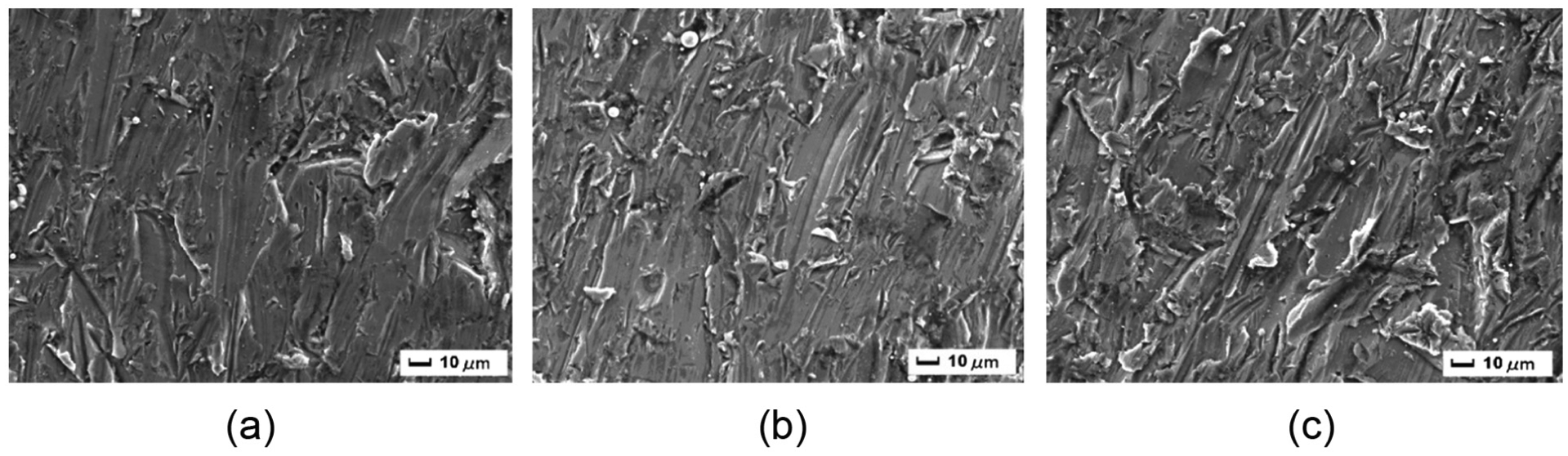
SEM images of cut sections at jet pressure of 320 MPa: (a) α = 0°, (b) α = 10°, and (c) α = 15°.
Surface morphology characteristics
Surface morphology features at α = 10° are illustrated in Figure 11 where the directions of abrasive particle velocity and transverse motion of the nozzle are denoted by Vp and Vt, respectively. Footprint patterns shown in Figure 11 are considerably different from those obtained with vertical impact. Furthermore, for each element, the distribution of local height is uneven and local height increases with standoff distance. With the motion of the nozzle, local heights increase as well. However, from Elements A–F, element-based average local height varies non-monotonously. In particular, in Figure 11(f), overall local height is fairly small compared with the other five elements. At this abrasive particle incidence angle, the range of standoff distance associated with Elements A–D can be deemed as optimal since favorite surface quality is consistently maintained.

Local height distributions on cut section at α = 10°: (a) Element A, (b) Element B, (c) Element C, (d) Element D, (e) Element E, and (f) Element F.
Local height distributions over selected elements at α = 15° are shown in Figure 12. From Elements A to F, the evolution of surface morphology is considerably different with that implied in Figure 11. For Element A, local height distribution differs appreciably from Figure 11(a) and the roughest zone is close to the nozzle. This disparity is associated with inhomogeneously dispersed abrasive particles at jet stream sections. As standoff distance increases, at Elements C, D, and E, another unique feature is perceived in the layers which are nearly parallel to the motion direction of the nozzle. The gradients of local height over these layers are remarkable. As standoff distance increases further, at Element F, surface morphology is similar to that indicated in Figure 11.

Local height distributions on cut section at α = 15°: (a) Element A, (b) Element B, (c) Element C, (d) Element D, (e) Element E, and (f) Element F.
Averaged local height
Local heights are averaged over each element and the results are plotted in Figure 13. In essence, the parameter of area-averaged local height amounts to the surface roughness of a given area. All the three cases manifest no explicit variation tendency of averaged height. The case of α = 0° possesses the minimum average height, which does not correspond to the smallest standoff distance. And the maximum average height is associated with the case of α = 15° and the position is further downstream. The case of α = 10° deserves special attention with the comparatively mitigated fluctuations of average height. Particularly, in terms of the consistency of averaged height with the variation of standoff distance, the behavior of this case is preferable relative to the other two cases.

Variation of area-averaged local height with standoff distance.
Conclusion
This study probes into the oblique impact of AWJ at ultra-high jet pressures. Both numerical simulation and experimental work are conducted. Features of oblique impact, reflected by von Mises stress, node displacement, and surface morphology are demonstrated from small-scale aspects.
At the initial abrasive particle velocities specified, typical resultant states of rebound, embedment, and penetration of the abrasive particle are visualized numerically. Von Mises stress distributions about the abrasive particle are not symmetrical with oblique impact. The stress distribution pattern adjacent to the abrasive particle is explicitly related to incident angle of the abrasive particle. As initial abrasive particle velocity increases, deformation near the abrasive particle attenuates, as is testified by transient variations of node displacement.
Experimental work facilitates a quantitative description of surface morphology based on practical cut sections. The surface morphology feature associated with oblique impact differs from its counterpart obtained under conditions of vertical impact. Such a distinction is intensified as incident angle increases. At the incident angle of 15°, rather irregular local height distributions are seen at intermediate standoff distances. At the incident angle of 10°, relatively smooth variation of area-averaged height over the range of standoff distances considered.
Footnotes
Academic Editor: M Ravichandran
Declaration of conflicting interests
The author(s) declared no potential conflicts of interest with respect to the research, authorship, and/or publication of this article.
Funding
The author(s) disclosed receipt of the following financial support for the research, authorship, and/or publication of this article: This work was supported by the National Science Foundation of China (Grant No. 51376081) and the Postdoctoral Science Foundation of Jiangsu Province of China (No.1201026B).