
Abstract
This article shows the methodology of building finite element models of composite constructions made of laminate composites reinforced with carbon fibre fabric (carbon-fiber-reinforced polymer). The models use a repeatable microstructure of a composite – a repeated unit cell – which is a three-dimensional truss built with one-dimensional beam finite elements. Thanks to this fact, the models reflect the internal structure of the composite. The model constants have been experimentally determined. Therefore, the influence of production technology of the composite on its mechanical properties has been considered. The modelling methodology has been used to calculate deflections of exemplary composite constructions. The results have been experimentally verified.
Introduction
Laminate composites reinforced with fabric or roving (carbon-fiber-reinforced polymer (CFRP)) belong to anisotropic bodies whose mechanical properties depend on component properties (reinforcement and resin) and their fraction in the composite, the number and the arrangement of reinforcement layers, the structure (weave) of the reinforcement in the layer and the production technology of the composite. Experimental studies of stress and deformation of real composite constructions prove that methods and calculation models used in engineering calculations are not always sufficiently precise. The composite is treated as a homogeneous material whose substitute technical modules (effective elastic properties: Young’s modulus E and Poisson’s ratio ν) are determined as a weighted sum of component modules with the weights resulting from their fraction in the composite – the so called law of mixtures.
Calculation models which take into account the internal structure of the composite, the number and arrangement of the layers, as well as the autonomy of the reinforcement and resin phases, come from the generalized Hooke’s Law, where the values of elements of elastic flexibility matrix are also determined with the use of the Mixture Law, for example, Abolinsz 1 and Skudra and Bulaws. 2
A different attitude based on the theory of thin-walled plates leads to the so called Lamination Theory and the calculation models described in some papers.2–5 The models were applied in professional finite element method (FEM) packages for engineering calculations (e.g. MSC Patran/Nastran). These calculation models of laminate composites do not take into account, among other things, the kind of weave of the reinforcement fabric or the stress distribution on the boundary of reinforcement and resin phases which have a big influence on the precision of engineering calculations.
The attempt to solve the problem is calculation models using the FEM which have been discussed recently in many papers. It is worth to mention micro-scale models where a repeating element of the internal structure of the composite – the so called repeated unit cell (RUC) – is modelled by means of relatively big number of finite elements mostly solid elements, reflecting the weave of the reinforcement fabric and the interaction of the resin and the reinforcement warp.6–9 In the example in the FEM model presented in Chen et al., 7 about 800 solid finite elements or in Zhang and Binienda 9 even more then 13,500 were used to model the RUC, compared to 12 beam finite elements used in the proposed model (Figure 1). A big number of finite elements and as a result, the complexity of the models makes them only little useful in engineering calculations of real constructions. The way to solve the problem is a two-stage procedure consisting of the micro-scale FEM model of the RUC made in the first stage being replaced, in the second stage, with one finite element with substitute material constants chosen to ensure the balance of the elasticity tensor and technical modules in both stages. 7 This leads to the mesoscale FEM model which can be used in engineering calculations.

FEM of the RUC for the reinforcement fabric with the plain weave: (a) the reinfircement fabric with the plane weave, (b) structure of the single RUC, and (c) structure of connections RUCs on layer and between layers.
It must be added that laminate composites unlike conventional constructional materials are usually made by manufacturers of ready products (light planes, yachts, part of vehicles and machines) in different production conditions which influence the composite mechanical properties. Therefore, the calculation model of the laminar composite should take into consideration the production technology of a particular manufacturer. The modelling methodology described below enables to consider the calculation model of both the internal structure of the composite and the production technology. It also ensures that the numerical efficiency is appropriate in engineering calculations of real composite constructions.
It is worth to stress that unlike finite elements used to model laminar composites available in commercial FEM packages (e.g. in MSC NASTRAN programme, there is a special generator for laminar composites), the proposed mesoscale model of the composite RUC (Figure 1) does not require determining substitute stiffness matrix for the finite element.
FEM model of a laminar composite
When working on the calculation model of a laminar composite, the following was assumed:
The model is to reflect the internal structure of a composite;
The composite will be treated as an inhomogeneous material consisting of reinforcement and resin phases, which differ in properties;
The model constants will take into account the conditions of the composite production;
The calculation model of a real composite construction will be made by replicating the microstructure – the RUC – characteristics of the composite;
The structure of the RUC and the method of the calculation model construction are to enable discretization of the geometric model of the real composite construction.
Elementary cell model
The suggested model of the RUC uses the Hrennikoff 10 idea according to which in the discrete model of a solid, the volume element is replaced with a three-dimensional truss built with one-dimensional beam elements. The beam element enables to take into account bending, tension and torsion and is characterized by the constant course of the shearing force with given final values. Therefore, it makes it possible to take into account shearing stresses influencing the damage and deformation of the composite which are usually omitted in other calculation models. The suggested FEM scheme of the RUC of the composite is shown in Figure 1.
The RUC is made of two pairs of reinforcement interwoven roving, one in the direction of x the other of y. Nodes were located in the points of the roving
It is worth to mention that the model of RUC may be easily adapted to reinforcement fabric with a different weave (i.e. of ribbed fabric).
Determining the model constants
In order to determine the numerical values of the model constants and at the same time take into account the conditions of composite manufacturing, a flat sample of the composite with the dimensions of 200 × 20 × 4 mm3 was made maintaining the production technology of real constructions of a particular manufacturer. Bending tests were performed on a universal testing machine (Figure 2).

Bending test of a flat sample: (a) support and load of the sample, (b) extensometers system for deformation measurement and (c) scheme of support and load.
The sample was made in a mould of 16 fabric layers made of carbon fibres 11 and the epoxy resin. 12 The force F was applied from 100 to 2700 N with a step every 100 N. The deformations were measured with the use of foil strain gauges glued on the upper and lower surfaces of the sample. Seven tests were performed and the results were averaged.
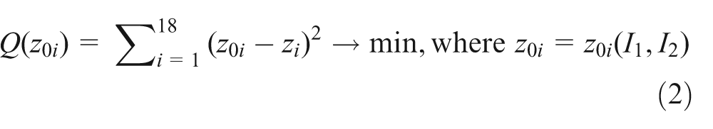
The roving of the reinforcement in the sample was arranged at 45° to its edge. During the bending test, additional characteristic flexure effect of the cross section perpendicular to the longitudinal axis of the sample was noted (Figure 3). The observed effect of the sample bending may be partially explained with Poisson’s effect. However, additional experiments showed that the sample bending depended on the orientation of the reinforcement roving according to the sample edge. Additional bending (in the cross section relative to the sample) was very small. Additional experiment showed that the described flexure effect did not take place in the sample in which the reinforcement roving was parallel to the edge of the sample. To prove the additional flexure effect of the cross section, a complimentary experiment was carried out where, in a special stand (Figure 4), the sample in the middle of its length was loaded with weights, and the deflections were measured by means of dial gauges in the test points distributed as shown in Figure 4(b). Deflections in test points were approximated by the surface with the equation

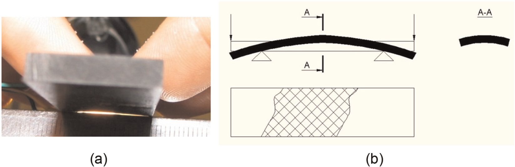
(a) Flexure effect of a cross section perpendicular to the longitudinal axis of the sample during the bending test and (b) reinforcement fabric arrangement in the sample.

Additional measurement of the sample flexure (a) support scheme, (b) test point distribution and (c) stand view.
where for
Young’s modulus of the warp was assumed according to the operation sheet of the manufacturer Er = 3.5 GPa. 12 The roving made of carbon fibre was determined from the tension test on a universal testing machine Ec = 62 GPa. The roving cross section was estimated on the basis of the weight of 10 roving segments of the length 1020 mm. Then, the mean mass of one of them was calculated (mc = 0.2007 g). Assuming the density of carbon fibre (ρc = 1.7 g/cm3), the mean area of cross section of a single roving was calculated (Ac = 0.1157 mm2).
Calibration of the RUC FEM model
Calibration based on the results of experimental studies enables to take into account the manufacturing technology of a composite of a particular producer. The FEM model of an RUC (Figure 1) was used to build calculation model of a flat sample of the composite whose deflections in chosen points were measured (Figure 2). Next, an optimization problem was formulated where the unknown decision variables were the moments of inertia of cross sections (vertical I 1 and oblique I 2) of the elements modelling the resin in the RUC model (Figure 1). Appropriate cross sections A 1 and A 2 were determined on the basis of the volume fraction of the resin in the composite. 13 It was assumed that the resin elements have square cross section. The objective function Q was the sum of squares of deviation values measured zi and calculated z 0i in 18 test points. The sum was expressed by the following equation
The solutions of the problem were values I 1 = 0.412 mm4 and I 2 = 0.603 mm4. The problem was solved with the help of Solver 200 module of the MSC Patran/Nastran package. The values I 1 and I 2 introduced to the model constants of an RUC showed good consistence of the results of calculations with the experiment. The mean error of the calculated and measured deflection was ε = 2%.
Examples of real composite construction modelling
Important factors deciding the usefulness of a calculation model are its numerical efficiency and algorithmization possibility (automation) of generating calculation models of real constructions. The problem was assessed on the examples of two types of constructions: one with regular shape (simple) and other one with irregular shape (complex). Both constructions were shell-type constructions, because this is where laminar composites are most often used.
Composite pipe
An exemplary composite construction with regular shape was the composite pipe with the outer diameter of ∅ = 244 mm and the length l = 1760 mm whose ends were glued with the bottoms with pins. The whole construction was the working roller of the carding machine. The pipe was built with 32 fabric layers made of carbon fibres with the plain weave and epoxy resin. To discretize the geometric model, a special programme – pre-processor – was made. The pre-processor enabled
Replacing the RUC with one finite element – superelement;
Scaling (increasing the size and decreasing the number of layers) of the superelement, where the scaled superelement required calibration with the use of the bending test of a flat sample in the way described earlier.
The use of pre-processor caused considerable reduction in the number of the model degrees of freedom. Therefore, its numerical efficiency was substantially improved. The FEM model of the analysed composite pipe which used RUC with the size of 2.5 × 2.5 mm2 had 80,901,504 degrees of freedom in 16 layers, and the model which used scaled superelement with the size of 10 × 10 mm2 had 148,598 degrees of freedom in four layers. The adequacy of the calculation model to the real conditions was examined by comparing the calculated and measured deflections of the working roller in the test stand (Figure 5).

Measurement of working roller deflections with composite pipe: (a) stand view and (b) measurement scheme.
The relative error of calculated deflections in relation to measured deflections was less than 8%, and the deflection lines in both cases showed the same course. 14 The problem was solved with the help of Solver 200 module of the MSC Patran/Nastran package.
Therefore, calculating deflections of real composite constructions with regular shapes may be performed according to the following procedure:
Taking the slice or preparing composite sample according to the technology of a particular manufacturer;
Assuming the RUC model which reflects the internal structure of a composite;
Defining superelement including RUC and the superelement scaling;
Calibrating superelement – the choice of element constants modelling resin;
Generating the FEM of a real composite construction as a result of geometric model discretization.
Aircraft wing
As an example of a construction with irregular shape additionally composed of components, the wing of a four-seat two-engined aircraft EM11 Orka was examined. The whole construction is made of laminar composite and shown in Figure 6.

Wing construction: (a) wing components and (b) sheathing structure.
The procedure methodology when calculating the wing deflection included stages (a), (b), (c) and (d) described before. However, the discretization of geometric model of such a construction was a separate problem to solve. A special pre-processor was elaborated which automated the problem in a two-stage procedure:
The discretization of a surface geometrical model of the wing components with the help of the standard MSC Patran pre-processor with the use of four-node finite shell CQUAD4 elements. 15 Owing to the shape and dimensions of the wing components, four dimensions of CQUAD4x,i elements were assumed (where x = A, B, C, D), and owing to different numbers of layers, seven types of CQUAD4x,i elements were assumed (where i = 1, 2, …, 7). As a result, a 28-element matrix of {CQUAD4x,i } finite elements was made. The elements were used for discretization of the wing components. Additional sheathing reinforcements in the form of the so called roving belts were modelled with the use of 1DCBAR beam elements. 15 The model consisted of 25,520 CQUAD4 elements and 8,863 1DCBAR elements altogether.
Replacing CQUAD4 elements with scaled superelements with the structure of RUC with the use of a special programme – remesher. In order to algorithmize the replacement, the theory of algebraic topology was used.16–18 An exemplary structure is made up of nodes (v 1, v 2, …, v 9), edges (k 1, k 2, …, k 12) and elements (e 1, e 2, e 3, e 4) (Figure 7). The standard pre-processor PATRAN as a result of discretization (stage 1) generates a DATA.BDF text file where the CQUAD4 elements are represented by node numbers in the form of a table of numbers. For an exemplary structure, it has the following form (equation (3))

Each row of the [BDF] table includes element number e and the list of nodes which define the CQUAD4 element. It is possible to build the incidence matrix of elements with the use of the list of common nodes

where 1 represents incidence in the node, whereas 0 indicates no incidence. In a similar way, one can build the edge incidence matrix with common nodes [Δ1]. In order to obtain the incidence matrix of elements

and the elements of the matrix


Scheme of the exemplary structure to remesh.
where [ET ] = [1111] is a 1-column matrix made of elements with value 1 equal in number to the number of structure elements.
The elements of the matrix [KBf′] represented multiplicity of the edges in the structure. After resetting matrix [KBf′] elements other than 1, one obtains a matrix [KBf] = [111101111] whose elements with value 1 form the chain of edges forming the boundary of the structure.
In a similar way, we determine a multiplicity matrix of the boundary nodes

and replacing elements with the value 2 with 1 results in a chain of nodes on the boundary of the structure

The matrix of the elements forming the boundary of the structure is obtained by multiplying matrices
after replacing elements with the value 2 with 1

The next step is to build adjacency matrix of the structure elements

Defining the 1DCBAR beam elements that are the edges of the structure will form superelement (RUC) which is performed as follows. First, it is necessary to check, with the use of matrix [EBf], whether the edge lies on the boundary. If this condition is met, using the matrix [VBf], the following step is checked, in which nodes of the edge lie on the boundary. For example, for element e 1, it is node v 1. With this node, one starts generating 1DCBAR elements, using indices of nodes forming elements stored in the set [BDF ] – for example, a 1DCBAR element is generated between nodes v 1 and v 5 (Figure 8(a)). Afterwards, using matrix [EE], element e 3 is found which is linked to only one node v 5. The procedure is repeated until the boundary of the structure is reached. This way, 1DCBAR elements modelling the reinforcement roving are generated (Figure 8(b)). In a similar way, elements modelling resin in the next RUC of the layer 1DCBAR (A 1, I 1) and 1DCBAR (A 2, I 2) are generated. Nodes of RUC in the next layers are generated by copying the preceding layer in the same or opposite direction to CQUAD4 element normal. As a result, elements CQUAD4 are replaced with superelements which have the structure of an RUC (Figure 8(c)).

Defining following elements 1DCBAR.
The procedure is repeated in the following iterations until they reach the edge. The detailed description is shown in Mirota. 19
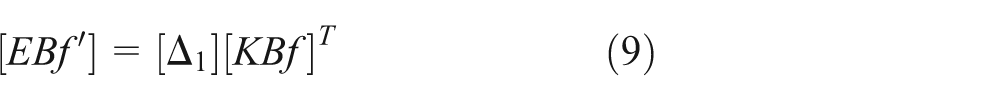
The calculation model of the wing (owing to the symmetry, half of the wing was modelled) consisted of 556,649 1DCBAR elements. The problem was solved with the help of Solver 200 module of the MSC Patran/Nastran package. It was experimentally verified measuring the deflection in the test stand shown in Figure 9.
Scheme of a test stand to measure the wing deflection.
During the experiment, the wing was loaded with the force F = 46 kN, and the deflection was measured in four test points (Figure 9). The comparison of the calculations and measurements are shown on the chart in Figure 10.

Wing deflection obtained as a result of the experiment and numerical calculations; SUPELM– FEM using the scaled superelement with the structure of an elementary cell, CQUAD4– FEM using CQUAD4 element and the Mixture Law for determining the element constants.
The comparison shows that the calculation model built according to the suggested methodology (SUPELM) gives results consistent with the experiment. The mean relative error in relation to the experiment is ε 1 = 8.9%. In comparison, Figure 10 shows that the results obtained for the FEM where standard CQUAD4 elements with constants determined from the Mixture Law were used. In this case, the mean relative error of the calculations as compared to the experiment was ε 2 = 43.5%. The calculation time was about 180 min for the computer with AMD Athlon(tm) 64 ×2 dual-core processor 3800 and 2 GB RAM.
Conclusion
The described methodology of building mesoscale FEM models of laminate composites reinforced with fabric, which uses a repeating unit cell (RUC) structure in the form of a space truss, is characterized by the following:
It allows taking into account the number and orientation of layers, autonomy of reinforcement and warp phases, as well as composite manufacturing process conditions, and, above all, modelling the reinforcement weave;
In the analysis of deformations of the real composite constructions, it provides adequacy of FEM models with reality, and good numerical efficiency of calculation models, also in the case of complex composite constructions;
It allows automating the process of discretization of the geometric model by replacing surface elements with superelements which have the structure of the composite unit cell.
Given the above, this methodology can be successfully applied in engineering calculations of composite construction deformations, especially when they are performed in conditions of small-lot or unit production.
Footnotes
Academic Editor: Magd Abdel Wahab
Declaration of conflicting interests
The author(s) declared no potential conflicts of interest with respect to the research, authorship and/or publication of this article.
Funding
The author(s) received no financial support for the research, authorship and/or publication of this article.