
Abstract
The rollover of road vehicles is one of the most serious problems related to transportation safety. In this article, a novel rollover prevention control system composed of rollover warning and integrated chassis control algorithm is proposed. First, a conventional time-to-rollover warning algorithm was presented based on the 3-degree of freedom vehicle model. In order to improve the precision of vehicle rollover prediction, a back-propagation neural network was adopted to regulate time to rollover online by considering multi-state parameters of the vehicle. Second, a rollover prevention algorithm based on integrated chassis control was investigated, where the active front steering and the active yaw moment control were coordinated by model predictive control methodology. Finally, the algorithms were evaluated under several typical maneuvers utilizing MATLAB/Simulink and Carsim co-simulation. The results show that the proposed neural network time-to-rollover metrics can be a good measure of the danger of rollover, and the roll stability of the simulated vehicle is improved significantly with reduced side slip angle and yaw rate by the proposed integrated chassis control rollover prevention system.
Keywords
Introduction
Rollover is an important safety issue for the vehicles with higher center of gravity (CG), such as sport utility vehicles (SUVs), trucks, and pickup vans. According to the 2009 report from the National Highway Traffic Safety Administration (NHTSA), 8732 vehicles were involved in fatal crashes due to rollover. The statistics of rollover accidents showed that 54.4% of vehicle occupant fatalities in single-vehicle crashes involved a rollover event. The proportion differs greatly by vehicle types: 44.1% of passenger cars occupant fatalities in single-vehicle crashes involved a rollover event, compared to 61.9% for pickup trucks, 53.4% for vans, and 70.1% for SUVs. 1 In recent years, chassis dynamic stability control systems that prevent vehicles from rollover accidents have been equipped more and more widely. Rollover prevention can be achieved by employing rollover warning and active anti-rollover systems.
The accurate detection of the risk of vehicle rollover is necessary for active rollover prevention. There are several kinds of rollover indices (RIs) developed for rollover prediction and warning. In 1987, Nalecz et al. 2 proposed rollover prevention energy reserve (RPER) which is based on energy function to investigate the rollover risk. In 2007, Yoon et al. 3 developed a dimensionless RI based on roll dynamics phase plane analysis. In 2013, Phanomchoeng and Rajamani 4 presented an RI including both vertical accelerometers and a lateral accelerometer for detecting the tripped and untripped rollover conditions. Stankiewicz et al. 5 proposed a new anti-rollover metrics, named the zero-moment point, to predict the rollover possibility sufficiently. At the same time, there are a lot of rollover researches which are based on the lateral load transfer ratio (LTR). In 2012, an LTR-based unified RI for heavy vehicles was proposed by Huang et al., 6 who extended the RI for single vehicle to multiple rollover indices (MRIs) for vehicles with trailers. In 2013, Larish et al. 7 developed a new predictive lateral load transfer ratio (PLTR) which performed better than the traditional LTR in the advanced time measure. Shi and Bao 8 presented a nonlinear rollover prediction model for heavy trucks based on LTR. In order to obtain the parameters of vehicle status in real time, the parameters were estimated utilizing the extended Kalman filter technique. In 2011, Rajamani et al. 9 represented an algorithm to estimate roll angle and CG height for calculation of real-time RI. In 2001, Chen and Peng 10 proposed a warning algorithm based on the time-to-rollover (TTR) metrics to estimate the time until rollover occurs. In 2011, Zhu et al. 11 represented an enhancement of the TTR metrics by introducing the Kalman filter technique, which improved the rollover warning system effectively.
Among these methods, the TTR can provide a super real-time prediction of rollover risk. However, a traditional TTR is based on the estimation of the vehicle states from a linear rollover model and predicts an impending rollover by single index. As the nonlinear characteristics of the vehicles are not considered, the accuracy of TTR estimation is limited. Neural network works effectively in the fields of expert system, mode identification, intelligent control, combinatorial optimization, and predication due to its effectiveness in processing nonlinear and adaptable information. 12 Among the various types of neural networks, the back-propagation neural network (BP-NN), which is a multi-layer feed forward network and trained by error back-propagation algorithm, is one of the most widely used. In view of the above advantages, it is applicable to achieve a more accurate TTR-based rollover risk prediction by applying BP-NN. In previous research, roll angle and roll rate were used to train the BP-NN, but at present, the vehicles are not equipped with roll acceleration sensor generally. So it is significant to find the combinations of some different vehicle variables which can describe the roll state of a vehicle and use them as a more practical way to perform the anti-rollover control.
Rollover stability can be improved by different dynamic control systems, such as four-wheel steering, active suspension, active stabilizer, or differential braking.13–16 Selim et al. 17 presented a robust rollover prevention controller design methodology based on active steering which could keep the magnitude of performance output below a certain level. Rajamani and Piyabongkarn 18 developed an integrated electronic stability control (ESC) using a new steer-by-wire technology to balance the performance among yaw stability, violence, and rollover prevention. Imine et al. 19 developed an active steering assistance system to prevent the rollover of heavy vehicles. They utilized the high-order sliding mode observer to obtain the parameters of lateral acceleration and height of the CG. Yu et al. 20 proposed an active roll control system utilizing the active suspension mechanism. This control system largely improved the roll stability of typical heavy-duty trucks. Parida et al. 21 represented an optimal control method to synthesize and distribute realizable forces in the active suspension to avoid rollover when the wheels lifted off the road. Miege and Cebon 22 proposed a new active roll stabilization system utilizing an active stabilizer for active torque distribution between front and rear axles. It can reduce the roll motion obviously. Chen and Peng 23 developed a differential-braking-based anti-roll method for SUVs, which showed improved roll stability. Licea and Cervantes 24 developed a novel robust switched braking controller based on RI for anti-rollover.
Although all of the above-mentioned systems can improve the vehicle stability, each system has its disadvantages and only works well within specific dynamic fields. By integrating some of these subsystems, their disadvantages can be compensated by each other and the vehicle roll stability would be improved more significantly. For instance, an active steering system can improve the maneuverability and stability and prevent the vehicle from rollover with less negative influence on other performance of the vehicle such as longitudinal velocity. However, it does not work so well in the case of a relative higher speed and a larger lateral acceleration. The independent braking control provides the additional yaw moment on a vehicle body and is good at reducing the lateral acceleration and the roll angle. Its advantage is more obvious especially under more severe steering maneuvers. But the brake forces on the wheels will reduce the vehicle speed apparently which indicates unwanted energy losses. Therefore, the integrated control of chassis dynamics control subsystems such as active front steering (AFS) system and differential braking system are researched for rollover stability enhancement. 25 While each chassis control system is designed for specific motion control and performance improvement, they may negatively impact others with potential conflict. Thus, it is necessary to utilize the optimal multi-input multi-output (MIMO) control methodology to combine multiple subsystems into a unified intelligent chassis control (ICC) system. Since the TTR is a faster-than-real-time warning metrics, model predictive control (MPC) method is suitable to design the anti-rollover controller.
In this work, the LTR is selected as the RI, and a 3-degree of freedom (3-DOF) rollover vehicle model and a TTR-based rollover warning algorithm are established. Then, the intelligent bionic artificial neural network is introduced to present a multi-parameter modified neural network time-to-rollover (NN-TTR) warning algorithm, and typical vehicle state parameters are selected to analyze and adjust the traditional TTR. Based on the accurate detection of TTR, the vehicles are actively controlled for rollover prevention by the differential braking system based on rule-based distribution strategy of the direct yaw moment and the active steering system which are coordinated by MPC theory. Finally, the NN-TTR algorithm and the ICC controller are validated using MATLAB/Simulink and Carsim co-simulation platform.
Overall controller architecture
In this study, a vehicle rollover prevention system is designed, whose overall structure is demonstrated in Figure 1.

Vehicle rollover prevention system’s overall architecture.
The vehicle rollover prevention system consists of upper and lower layers. The upper layer is a rollover warning system, which can estimate the parameters of vehicle status in real time using a 3-DOF vehicle model and calculate RI and NN-TTR metrics to detect the rollover tendency. Once the rollover risk occurs or the NN-TTR decreases to a predefined threshold, the ICC controller in the lower layer is triggered to take an active intervention and mitigate the roll motion of the vehicle. The ICC controller utilizes the MPC optimal methodology to calculate the control inputs of the active front wheel steering angle Δδ and the active yaw moment ΔM based on a 2-DOF reference model. The reference model provides the desired yaw rate ωrd and the side slip angle βd. The active front wheel steering angle Δδ is applied by the actuator of the AFS, and the active yaw moment ΔM is implemented by the differential braking based on the yaw moment distribution strategy. The vehicle rollover prevention algorithm is described in Figure 2.

Vehicle rollover prevention algorithm.
Rollover warning metrics
Vehicle model
It is important to develop a reference model that describes the vehicle motion with sufficient accuracy and convenience for rollover warning and anti-rollover controller design. A 3-DOF linear vehicle model is used in this work, as shown in Figure 3. This model involves a bicycle model with 2-DOF (lateral motion and yaw rotation) and a roll dynamics model of the vehicle with the degree of freedom of roll angle. Although this linear vehicle model is simple, it could describe the vehicle lateral acceleration, roll angle, roll rate, and yaw rate accurately in the linear region of the vehicle motion, and it could meet the demand of the rollover warning and anti-rollover control.

3-DOF vehicle model.
Longitudinal and vertical motions are supposed to be unchanged, and the equations of motion for this vehicle model are as follows


where lateral acceleration

And the front and rear wheel cornering forces


where m is the mass of vehicle; ms is the rolling sprung mass; ωr is the yaw rate; β is the side slip angle; hcm is the height of CG from ground; h is the distance from CG to roll center; δ is the front wheel steer angle; ay is lateral acceleration; ϕ is the roll angle of the sprung mass; cϕ is the roll damping coefficient; kϕ is the roll stiffness; D is wheel track; Ix is the inertia of sprung mass roll moment; Iz is the inertia of vehicle yaw moment; αf and αr are front and rear wheel side slip angles; MZ is the yaw moment generated by differential braking; kf and kr are front and rear wheel cornering stiffnesses; a and b are the distances from the vehicle CG to the front and rear axles, respectively; vx and vy are the longitudinal speed and lateral speed, respectively; FZL and FZR are the vertical loads on left and right wheels, respectively; and Ff and Fr are the front and rear wheel cornering forces, respectively.
LTR rollover index
The main objective of a rollover warning algorithm is to provide information to the drivers or vehicle active safety systems about the upcoming rollover risk and give them sufficient time to react for accident prevention.
There are multiple static variables such as lateral acceleration and roll angle, which can be chosen as RIs. However, these indices are not normalized and their thresholds differ by vehicle parameters. To make the algorithm more universal, the lateral load transfer rate (LTR) is selected as the RI in this article. The LTR defines vehicle rollover as the moment when either the left or the right wheel of the vehicle experiences lift-off from the ground, which is defined as

The LTR is non-dimensional and normalized, and its value ranges from 0 to 1. The value of LTR is 1 in rollover cases and less than 1 in other cases. In actual applications for rollover warning, the LTR threshold for determining rollover threat is very important. If the threshold is set too low, the LTR will provide a warning or activate the rollover prevention system too frequently during safe and normal driving. But, if the threshold is set too high, a preventive action may be activated too late to avoid vehicle rollover. In this study, the LTR threshold is set as 0.9 according to previous studies. 26
As the vertical load varies with time and is difficult to measure directly in real time, it is hard to calculate the LTR online. Therefore, the LTR should be deduced by the vehicle structure parameters and state parameters

TTR metrics
To predict impending rollover danger in the future, so as to correct the dangerous maneuver and avoid the rollover accident before the threshold value is exceeded, a TTR metrics is proposed by Professor Chen 10 and Chen and Peng. 23 Assuming the input (steering angle) stays unchanged in the foreseeable future, TTR is defined as the time it takes for the vehicle tires of any side to lift off.
The TTR–time curve is shown in Figure 4. Supposing that the current time is ts and the actual vehicle rollover moment is tr, the warning time should be: TTR = tr − ts. Therefore, the desired TTR–time curve is a straight line of slope being equal to −1 in rollover cases. If an arbitrary point A on the line corresponds to the rollover warning time TTR = Y, the time coordinate of point A should be tr − Y, which means that the vehicle will rollover in Y seconds. It indicates that the vehicle rollover happens if TTR is equal to 0.

Time-to-rollover notion.
The flow chart of TTR determination algorithm based on LTR is shown in Figure 5. The LTR RI is calculated by the discrete 3-DOF reference model with sampling time Ts. The number of steps N is recorded as soon as the RI reaches the threshold for the first time. Thus, the TTR is determined by N × Ts, which indicates that the vehicle is going to roll over in N × Ts seconds.

Flow chart of TTR determination algorithm based on LTR.
The warning process is a countdown process. The smaller the TTR value, the higher rollover risk the vehicle is at. Under normal driving conditions, the TTR is usually very large and may even approach infinity. For implementation considerations, we preset the rollover warning threshold as X, and the TTR is set to be X seconds when there is no rollover risk. In other words, if N × Ts is larger than X, TTR = X is output, which means the vehicle is safe enough now. The threshold can be specified differently for different vehicles or for different aggressiveness of roll motion predictions. In this study, the rollover warning algorithm provides warning information for the active anti-rollover controller which can respond in a very short time, so the TTR threshold is set as 1 s.
Neural network TTR metrics
As mentioned earlier, the desired TTR–time curve should be a straight line with slope −1 in rollover cases and a straight line of positive constant X in non-rollover cases. However, the 3-DOF linear vehicle model employed here is too simplistic and unable to describe the nonlinear dynamical characteristics of vehicle. Furthermore, the LTR which is selected as the only RI cannot represent the comprehensive driving states of the vehicle. Thus, the traditional rollover warning algorithm cannot ensure the desired TTR slope (see the simulation results in section “Rollover warning”).
Therefore, an intelligent bionic artificial BP-NN is introduced to present a multi-parameter modified NN-TTR warning algorithm in this study. The structure of the NN-TTR-based rollover warning algorithm is shown in Figure 6.

Structure of rollover warning based on NN-TTR.
There are four layers in the designed BP-NN in total. The input layer has three neurons and the inputs are the traditional TTR and two typical vehicle state parameters, which will be described below. There are two hidden layers with five neurons and one neuron, respectively. The output layer only contains one neuron and the output is the regulated NN-TTR. The tansig functions are utilized as output functions of the neurons. The BP-NN is trained by the error between the output TTR and the desired TTR.
The output of the input layer

The input and output of the first hidden layer are as follows

The input and output of the second hidden layer are


The input and output of the output layer

where the superscripts (1), (2), (3), and (4) represent the input layer, the first and second hidden layers, and output layer, respectively; w is the weighting coefficient; f is the activation function of the neuron

The performance index function of the neural network is as follows

where T(4) is the target output.
In order to investigate the impacts that the vehicle state parameters have on rollover warning and select the appropriate state parameters to modify the traditional TTR, three sets of vehicle state parameters often used for active safety control are analyzed, as shown in Table 1. They are Case 1: longitudinal speed and front wheel steer angle, which are the inputs of the 3-DOF model for LTR calculation and have a great impact on the vehicle status; Case 2: yaw rate and lateral acceleration, which are two important parameters characterizing the stability of the vehicle; and Case 3: roll angle and roll rate, which can be directly used to describe the vehicle roll status.
Selection scheme of vehicle state parameters.

Typical maneuvers are selected to train the BP-NN by the three sets of parameters to modify the traditional TTR and make the predicted rollover time reaching the desired value.
The structure of NN-TTR regulator is shown in Figure 7. The selected training cases are shown in Table 2. The training of the neural network will be stopped when the preset performance index is satisfied, where the preset performance index is the difference between the desired TTR (a straight line with slope of −1) and the output of the NN-TTR.
Structure of NN-based TTR regulator.
Simulation and training conditions of rollover warning.
ICC rollover prevention controller design
Although the rollover warning algorithm could predict impending rollover danger in the future, it is hard for human drivers to respond in such a short time. Thus, an active control may be necessary to assist drivers for rollover prevention. As mentioned in section “Introduction,” the rollover prevention control proposed in literatures are mainly achieved through the yaw control, the load transfer minimization, or the lateral force deduction. Among these methods, the yaw control by the differential braking and the lateral force deduction by the active steering control are easy to realize and considered as the most effective way to improve vehicle yaw and roll stability. According to the algorithm of rollover warning above, MPC method is used to design an anti-rollover controller in this article, which could integrate AFS and direct yaw moment control (DYC) systems.
MPC controller design
The actual and expected side slip angles and yaw rate are selected as the inputs of the MPC controller, and the outputs are expected active yaw moment and front steering angle.
A 2-DOF bicycle model is used for the MPC controller design. The vehicle state space equation is

where

To maintain lateral and roll stability, both the yaw rate and side slip angle should be restricted within a stable field. The desired yaw rate can be obtained from steady-state yaw rate gain of the reference model
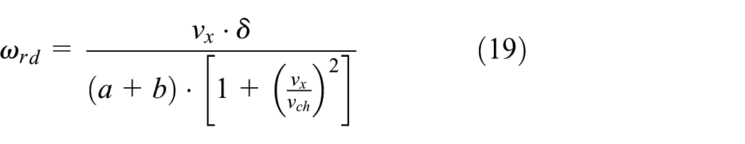
where

In addition, the desired yaw rate should be constrained by the road friction coefficient

To prevent rollover, the desired side slip angle can be chosen as

The 2-DOF model is discretized as the following prediction model

where

TMPC is sampling time.
The predictive output vector

where

where Hp and Hc are the prediction and control horizons, respectively, and Hc ≤ Hp.
Considering the following cost function
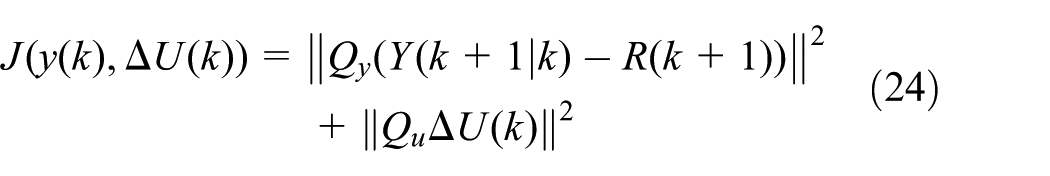
where Qy and Qu are weighting matrices and R(k + 1) is the reference for the output tracking variable

At each time step, the following optimization problem is solved

subjected to


where the inequalities (27) limit the control inputs, (28) constrain the changes of the control input, while (29) are constraints on system output variables.
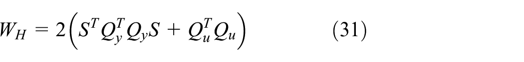
Obviously, this is a typical constraint optimization problem, and it can be transformed into a quadratic programming problem and easily solved by standard programs

where


Aconst and bconst are the constrained matrices.
Then, the first sample of the results is used to compute the optimal steering and braking torques and the result state feedback control law is


Control allocation of the direct yaw moment
The direct yaw moment is implemented by the differential braking control. Most of the existing methods used for the DYC distribution are rule-based. A rule-based allocation method calculates and applies the active brake force onto a specified wheel to produce the desired yaw moment. Researches have shown that when a vehicle is turning, the braking force applying on the front outer wheel or the rear inner wheel is more efficient than forces being applied to others. 27 For a vehicle showing under-steer, a compensation yaw moment in the same direction of the yaw rate can be obtained by imposing the brake control on the rear inner wheel. While if there is an over-steer trend, it can be reduced by applying the brake force on the front outer wheel to generate a correction yaw moment in the opposite direction of the yaw rate.
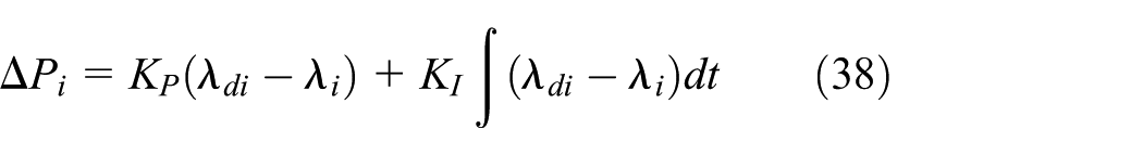
After the brake wheel is specified, its target slip ratio λdi should be calculated according to the desired yaw moment, and the target brake pressure Pi can be calculated based on the target slip ratio λdi and the actual slip ratio λi consequently. At last, the brake pressure Pbrake can be realized by the accurate control of the hydraulic brake actuator. The yaw moment control architecture used in this article is shown in Figure 8.

Yaw moment control architecture.
When a vehicle is at risk of rollover, it is under the over-steer state. Therefore, active braking on the front outer wheel is applied. The compensation yaw moment is
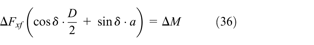
where ΔFxf is the longitudinal force increment of the controlled wheel.
The tire longitudinal force increment can be written as a function of the slip rate and its increment 27

where λ is the tire longitudinal slip ratio.
Thus, the target slip ratio of the specified tire can be obtained. A proportional integral (PI) controller is used to get the increment of desired brake pressure according to the error between the target and the actual tire slip ratio
At last, the yaw moment distribution can be achieved by the accurate control of the hydraulic brake actuator.28,29
Simulation
The rollover warning and ICC-based rollover prevention algorithms were validated using MATLAB/Simulink and Carsim co-simulation platform. The parameters of the vehicle model used in simulation are listed in Table 3.
Parameters and values of the vehicle model.

In order to evaluate the effectiveness of rollover prevention algorithms, complex open-loop maneuvers which can trigger the vehicle rollover are selected. 30 Kou et al. 31 tried to find a worst-case maneuver to describe the most dangerous situation without the drivers intervene for integrated chassis control system evaluation. In this article, the fishhook maneuver and step steer maneuver are chosen, which are shown in Figures 9 and 10, respectively, the maximum steering wheel angle is 294° for fishhook maneuver and 180° for step steer maneuver.
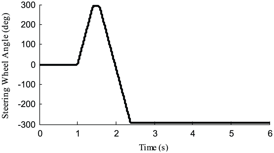
Fishhook maneuver.
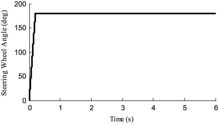
Step steer maneuver.
Rollover warning
In order to investigate the performance of the rollover warning algorithms, simulations were carried out. The vehicle was driven on the road with adhesion coefficient of 0.85, and the initial speeds of 80 and 110 km/h were specified for both fishhook and step steer maneuvers.
The simulation results about the rollover warning algorithms are illustrated in Figure 11, and the statistical results are shown in Table 4.

Simulation results of rollover warning algorithm based on NN-TTR: (a) Fishhook(80km/h) simulation results, (b) Fishhook(110km/h) simulation results, (c) Step steering(80km/h) simulation results, and (d) Step steering(110km/h) simulation results.
Statistical analysis results for rollover warning algorithms.
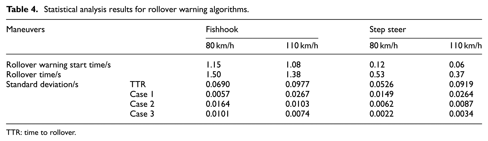
TTR: time to rollover.
It can be seen that all of the proposed rollover warning algorithms can predict impending rollover danger in the future, but obviously, the slope of the conventional TTR is not −1 in rollover cases. It means it will output a false alarm when the slope is steeper and cause the drivers too nervous or trigger the active controller too frequently. Instead, if the slope is smoother, it will fail to predict the danger and there would not be enough time to prevent the rollover for the active controller.
The detailed view shows that the slopes of the NN-TTR are closer to −1. Compared with the conventional TTR, the standard deviations of the errors between NN-TTR warning time and ideal rollover warning time are significantly reduced, which indicates that the introduction of the vehicle state parameters can improve the accuracy of rollover warning.
It is seen that the standard deviation of Case 3 is minimum, which is because the roll angle and roll rate can describe the vehicle roll state directly.
Although the longitudinal speed and front wheel steer angle are the inputs of the 3-DOF vehicle model for LTR calculation, the correction effect of Case 1 is not satisfied as the roll response is greatly influenced by the vehicle’s nonlinear characteristics. It is seen that the standard deviation of Case 1 is larger than the other two cases.
The yaw rate and lateral acceleration are important vehicle parameters which affect the vehicle roll state indirectly, so the correction effect of Case 2 is also satisfied.
At present, the vehicles are not equipped with roll acceleration sensor generally, but the yaw rate sensor and lateral acceleration sensor can be shared by the stability control system ESC or chassis dynamics management system which are widely used in modern vehicles. Although the correction effect of Case 2 is not the best, it has more advantages in practical usage.
Rollover prevention control
The performance of the ICC anti-rollover controller was evaluated through simulations carried out under both the fishhook maneuver and the step steer maneuver.
Figures 12–16 show the simulation results of fishhook maneuver for the vehicle with and without anti-rollover control. The vehicle was driven at an initial velocity of 90 km/h on the road with adhesion coefficient of 0.85.

Steering wheel angle for fishhook maneuver.

Yaw rate of the vehicle for fishhook maneuver.

Side slip angle of the vehicle for fishhook maneuver.

Roll angle of the vehicle for fishhook maneuver.
Controlled brake forces for fishhook maneuver.
Figure 12 shows the steering wheel angle input with and without active steering control. It should be noticed that the uncontrolled vehicle cannot finish the 6-s procedure and the uncontrolled steering wheel angle only depicts the open-loop input of the steering wheel, which is the same in the next simulation.
Figures 13–15 show the yaw rate, side slip angle, and roll angle for the controlled and uncontrolled vehicle separately. Figure 16 shows the brake forces applied on each wheel.
It could be seen that the roll angle and the side slip angle increased sharply as soon as the vehicle without control went into the “hook” process. Furthermore, the yaw rate also reached a valley value of −1.2 rad/s. Finally, the vehicle rolled over at 3.46 s and the simulation terminated. When a vehicle with higher CG steers sharply on a high-friction road, rollover might happen because of the overlarge lateral acceleration, which is determined by its large longitudinal velocity and small turning radius. In other words, the vehicles are always over-steering extremely when rollovers happen. It is why rollover is always accompanied by large yaw rate and side slip angle. Thus, the NN-TTR can use side slip angle and yaw rate as modification factors effectively, and the integrated chassis control method based on 2-DOF reference model can work well on anti-rollover control.
With control, the ICC controller was triggered properly and both active steering angle and brake forces were applied. As a result, the magnitudes of yaw rate, side slip angle, and roll angle of the vehicle were all reduced and maintained at a lower value. The vehicle kept stable and did not roll over in the 6-s simulation.
Figures 17–21 show the simulation results of step steer maneuver. The vehicle was driven at an initial velocity of 100 km/h on the road with adhesion coefficient of 0.85.

Steering wheel angle for step steer maneuver.

Yaw rate of the vehicle for step steer maneuver.
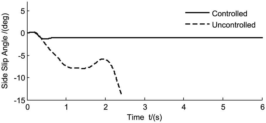
Side slip angle of the vehicle for step steer maneuver.

Roll angle of the vehicle for step steer maneuver.

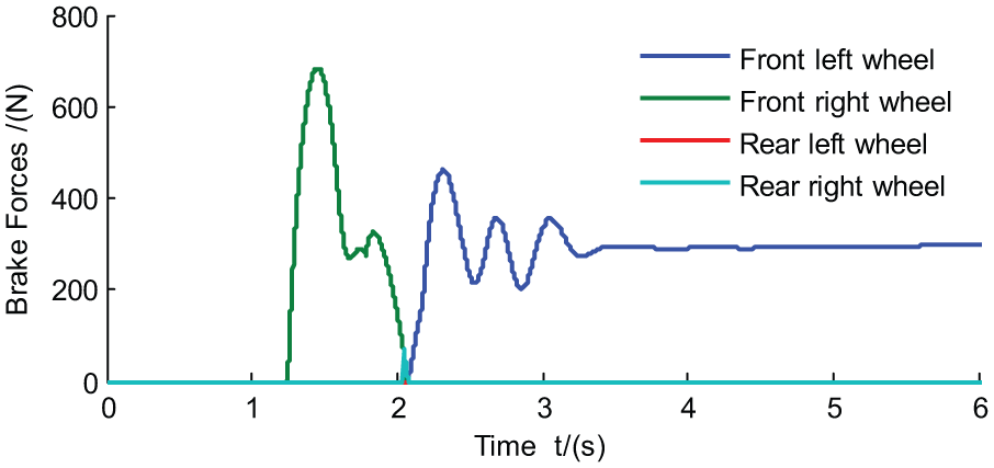
Controlled brake forces for step steer maneuver.
Figure 17 shows the steering wheel angle with and without control. Figures 18–20 show the yaw rate, side slip angle, and roll angle for the controlled and uncontrolled vehicle separately. Figure 21 shows the brake forces on each wheel.
It is seen that the vehicle without any control is also unstable. It side-slipped and rolled even more severely than it performed in the fishhook maneuver simulation. The vehicle rolled over at 2.42 s finally when the simulation terminated.
While the controlled vehicle kept stable in the 6-s simulation, the roll angle and side slip angle of the vehicle were restricted in stable fields with the reduced yaw rate.
The results indicate that the algorithm proposed in this article can predict the rollover risk and avoid impending rollover effectively.
Conclusion
The TTR-based rollover warning algorithm can achieve the rollover warning. However, it is not precise enough and might lead to premature or delayed warning. The establishment of the NN-TTR metrics based on the BP-NN technology and the vehicle state parameters improved the accuracy of rollover precaution time and laid a good foundation for the active anti-roll control. The effect of Case 3 which uses the roll angle and roll rate to modify the TTR metrics is the best. The Case 2 utilizing yaw rate and lateral acceleration also works satisfied and has more advantages in practical use.
A rollover prevention control system composed of rollover warning and integrated chassis control algorithm is proposed. Simulation results indicate that the rollover risk can be predicted and avoided effectively. The roll angle, side slip angle, and yaw rate of the vehicle under severe steering maneuvers can be restricted in stable fields, and the overall vehicle performance can be improved.
Footnotes
Academic Editor: Yaguo Lei
Declaration of conflicting interests
The author(s) declared no potential conflicts of interest with respect to the research, authorship, and/or publication of this article.
Funding
The author(s) disclosed receipt of the following financial support for the research, authorship, and/or publication of this article: This work is partially supported by National Natural Science Foundation of China (51105169, 51205156, and 51475206) and Jilin Province Science and Technology Development Plan Projects (20140204010GX).