
Abstract
The working state of equipments such as wind turbines, cranes, and excavators is directly affected by the damage of the slewing bearing. Condition monitoring system is a good method to identify the defects; however, the measuring range and distribution of the sensors have important influence on the monitoring efficacy. Due to the thin-wall and cyclic structure characteristics of a slewing bearing, the defect characteristic response is unusual and unknown. To solve this problem, a finite element model for local defect on the raceway of a slewing bearing was established by ABAQUS, and the operating process of the slewing bearing was simulated based on the explicit dynamic finite element algorithm. The pulse waveforms of vibration responses under different defect sizes are obtained, and the influencing mechanism of the damage sizes on the slewing bearing was studied. The simulation results show that the increase in defect length is the dominant influence on the operation of a slewing bearing and the effect of height is negligible under the same conditions. Furthermore, the explicit dynamic finite element analysis model was reasonable by comparing the simulation results with the test results. Therefore, the localized defect on the raceway surface of a slewing bearing can be reflected by finite element simulation analysis, and the analytical results can help develop the raceway damage monitoring system of a slewing bearing.
Introduction
Slewing bearing, as a key component, connects the machine structural parts, transfers loads, and allows relative rotation between them. It is widely used in excavator, cranes, mining equipment, port hoist and military, scientific research equipment, and so on. 1 Especially in the wind industry, the single-row four contact-point slewing bearing is adopted as the yaw bearing 2 to transfer axial (Fa), radial (Fr), and tilting moment (M) loads, and the rotational movement between generators and tower is realized. Given the importance of the slewing bearing on the mechanical structures and the complicated working condition, it may directly affect the normal operation of equipment once a failure happens and even causes huge economic losses and casualties. Because the damage mechanism and its development situation are not clear, the range and distribution of the detecting elements are selected mainly by experience rather than by theoretical guidance. It leads to weak signals, low signal-to-noise ratio, and poor accuracy of the fault identification. Therefore, the dynamic simulation of the slewing bearing with localized defect and the exploration of dynamic response caused by the defect have important practical guiding significance for monitoring system construction on the raceway damage of the slewing bearing.
As the important components of engineering equipment, slewing bearing is widely studied by many scholars. Amasorrain et al. 3 analyzed the difference between the two and four contact-point slewing bearing and gave the load distribution of a four contact-point slewing bearing and then got maximum load of the rolling elements. Kania 4 applied the finite element method to calculate and analyze the load capacity for rolling elements of the slewing bearing and gave the load deformation of rolling elements under the working conditions. Flasker et al. 5 carried out the numerical analysis on the raceway surface crack propagation of the slewing bearing and studied the crack propagation situation and raceway contact pressure distribution when the contact angle is different. Liu 6 conducted the condition monitoring experiment of the slewing bearing and the grease has been analyzed to find out the content of iron. Finally, the wear status of the internal raceway and the service life are studied according to the results of the analysis. Caesarendra et al. 7 performed the accelerating life test for slewing bearing to make it damage naturally, and the extracted vibration signals are analyzed by the empirical mode decomposition (EMD) and ensemble empirical mode decomposition (EEMD) method, respectively, in order to obtain the accurate damage information of the slewing bearing. Žvokelj et al. 8 collected the vibration and acoustic emission signals based on the slewing bearing condition monitoring experiments. The EEMD–multi-scale principal component analysis (MSPCA) method was applied in adaptive signal decomposition, and the fault feature components were extracted to identify local defect of the slewing bearing.
These studies mostly focus on the load distribution, condition monitoring, and signal processing rather than the raceway damage mechanism, damage development, and its impact. But if the damage mechanism is unknown, the type and range of sensors is difficult to choose; therefore, the choosing of sensors is baseless in the previous researches. In addition, the finite element dynamic simulation method has been used in the bearing research and analysis9,10 more and more widely. These references indicate that this work mainly focuses on the static analysis of the slewing bearing rather than dynamic research of the bearings. However, all of the static researches of the bearings provide a lot of help for the next dynamic research of the bearings. For example, based on this work, Li et al. 11 research the dynamic mechanical properties of single-row slewing bearing by the explicit dynamic algorithm. The distribution and variation of obtained Mises stress provide theoretical foundation for researching the bearing raceway damage. Therefore, it is necessary to apply the dynamic simulation analysis method for slewing bearing study with the localized defects and explore the influence mechanism of the damage sizes. It is a new important research field and can provide powerful basis for online evaluation of the raceway damage.
Type 010.40.1000 slewing bearing 12 was taken as the research object and the geometry sizes of damage were considered in this article. This slewing bearing can satisfactorily fulfill the requirements of the experimental verification, and the experimental verification can be easily carried out because the dimension of this slewing bearing is quite small. The defect models of different parameters were constructed to simulate the raceway spalling damage. According to the actual working condition, the external load, rotational speed, and other constraints were imposed to the models. The explicit dynamic finite element algorithm was adopted during the simulation analysis, and the influence mechanism of the damage size was obtained by analyzing the stress distribution on the surface of the slewing bearing raceway and the vibration acceleration response around the defect.
Finite element analysis and basic theory
3D solid model
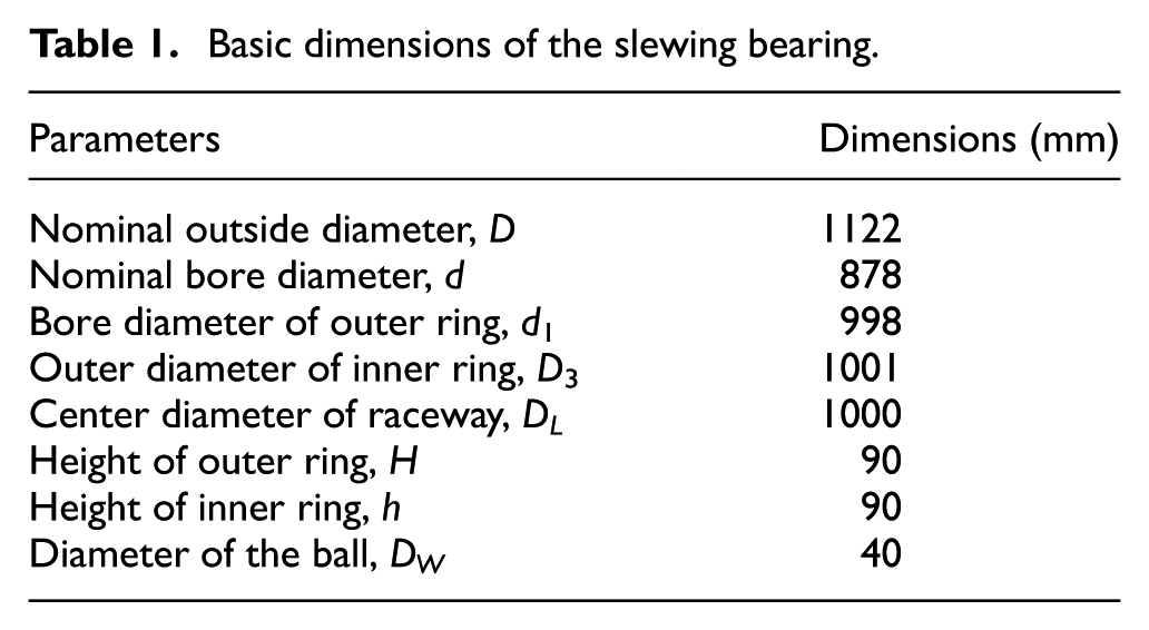
The single-row slewing bearing is mainly composed of outer ring, inner ring, cage, and rolling elements. Type 010.40.1000 slewing bearing is taken as the research object, and the finite element analysis (FEA) model is established according to the basic dimension parameters provided by the mechanical industry standard document JB/T 2300-2011 12 and the basic dimensions are shown in Table 1.
Basic dimensions of the slewing bearing.
The single-row slewing bearing model is established in the finite element software ABAQUS, and the precise modeling of inner and outer ring raceway is very necessary because the local spalling defect on the raceway is the key part of the analysis. The groove curvature radius r, contact angle

where Z is the number of rolling elements; the actual engineering parameter a usually takes 1.25 13 and the other parameters are as shown in Table 1.
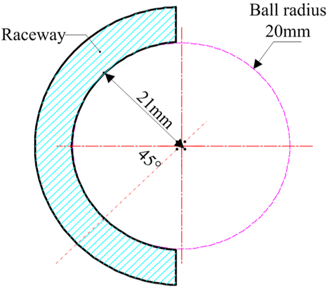
Horizontal cross section of a slewing bearing.

3D model of the slewing bearing.
Local defect of the raceway
Usually, slewing bearing does not make the whole circle movement but moves within a certain angle range, and it is commonly found in the slewing bearings of excavator and wind yaw bearings. In the range of the movement, there is a high intensity of periodic contact load between rolling elements and raceway. Therefore, it easily causes wear, crack, pitting, and the other fatigue defects, and with the contact fatigue becoming worse, it will eventually lead to fatigue spalling. 14 Especially in the overloading area and the quenching soft belt of the raceway, the local spalling defect appears easily which will reduce the carrying capacity and service life of slewing bearing.
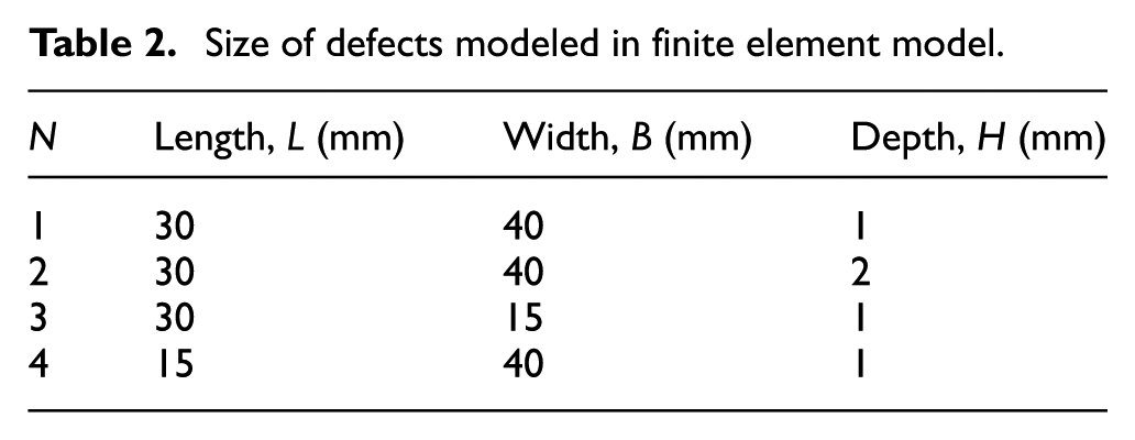
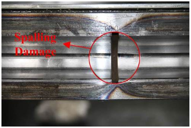
Once the spalling appears on the raceway and develops into a certain scale, the transient impact will be induced by the mechanism of the local unloading and overloading. The stress and acceleration with certain regularity will form on the outer surface of the rolling ring if the transient impact strength is enough. Figure 3 shows a spalling photo which is an intermediate state provided by the slewing bearing manufacturer. The spalling damage on the raceway is mainly composed of continuous spalling pits, and it will grow until a whole pit forms. According to the spalling sizes on the raceway and its approximate shape, for the modeling’s sake, a rectangular spalling damage model was created on the inner ring raceway surface as shown in Figure 3(b). Based on the basic sizes of the continuous spalling shown in Figure 3(a), the basic size of the rectangular spalling damage was obtained as listed in Table 2. N1 and data for N2–N4 were derived from N1 to find out which dimension has influenced the slewing bearing operation mostly. By analyzing the stress and acceleration corresponding to the defects on raceway surface and comparing the values with the simulation results without any defects, the effects of local spalling defect on the raceway are obtained.
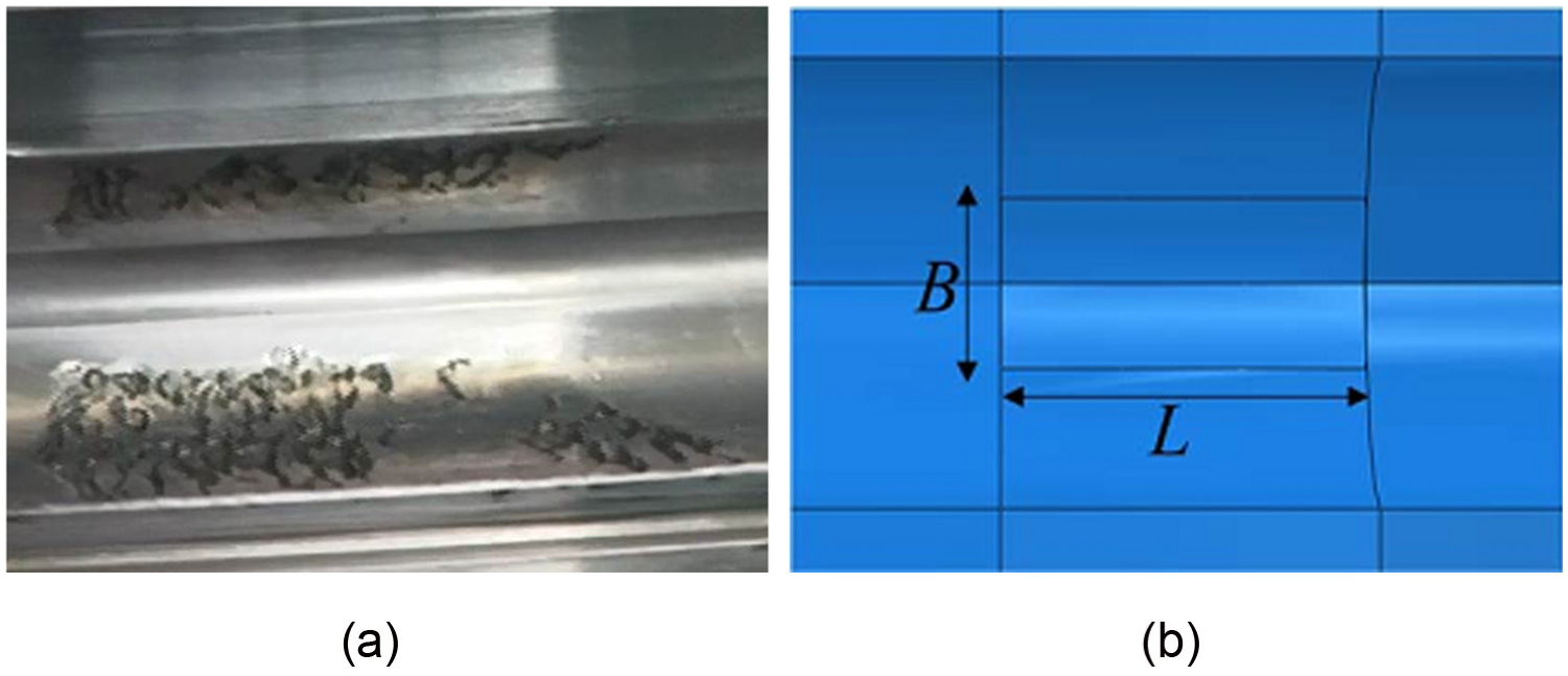
Spalling damage on the surface of inner raceway: (a) continuous spalling pits and (b) rectangular spalling damage.
Size of defects modeled in finite element model.
Materials and mesh
According to the standard file, 42CrMo is usually taken as the rolling ring material for a slewing bearing in order to ensure the low-cycle fatigue characteristics. GCr15SiMo and nylon 1010 are often used to produce the rolling elements and isolation block, respectively. 15 The differences of material properties of the quenching layer of the raceway surface are ignored herein. The main mechanical parameters of the materials are listed in Table 3.
Material mechanics parameters.

The accuracy of the simulation results is mainly dependent on the quality of the mesh generation. A lot of components are contained in a slewing bearing, so the contact mechanism of slewing bearing motion is complex. In order to accelerate the computational speed, the mounting holes for bolts have been ignored without influencing the accuracy of the analysis and the raceway, especially the spalling area is meshed finely. The partition technology is used to cut the inner ring and separate the defect area from the whole model. The element type C3D8R is chosen to ensure the ability of large deformation and stress strengthening, where C means continuum, 3D means three-dimensional unit, and 8 represents the node number of an element. In order to achieve a convergence analysis, the mesh should be structured with a higher density at the position of contact, such as the rollers, which is illustrated in Figure 4(b). Especially at the defect position, finer local mesh is utilized as shown in Figure 4(a). The medial axis algorithm and sweep meshing technology are used to the meshing in order to ensure that the finite element mesh is homogeneous and high quality. The inner ring is finally divided into about 8217 hex elements. The meshing method is applied to other parts similarly, and part of the finite element mesh is shown in Figure 4.

Finite element mesh of major components: (a) raceway with defect and (b) ball.
The explicit dynamic theory
The central difference method 16 has been adopted to solve the motion equation in ABAQUS/Explicit. The dynamic condition of a time period is utilized to calculate the dynamic conditions of the next period time. This means that the results of the initial iterative step are used to be the computational condition of the next iterative step. The final iterative results are obtained by such analogy. At the beginning of the increment step, the dynamic equilibrium equation is

where M is the mass matrix, P is the external force, I is the element force, and

The acceleration

In the same way, the displacement changing value is obtained by time–velocity integral and added to the displacement value at the beginning of the increment step. So, the displacement value u at the end of increment step is as follows

In conclusion, at the beginning of the increment step, an acceleration which meets dynamic equilibrium conditions is provided. According to the known acceleration, the node velocity and displacement are obtained through the explicit time integration. Herein, the explicit means that the results only depend on the initial value of acceleration, velocity, and displacement at the beginning time.
In order to ensure that the acceleration is approximately constant during the period, the time increment needs to be small enough which leads to tens of thousands of time increments in an analytical problem. However, the computational cost of every increment step is very low because it is not necessary to solve the simultaneous equations at the same time. Therefore, the explicit dynamic algorithm takes less computer burden and the calculation speed is faster. If adopting the implicit algorithm, the increment steps are less than the ones in explicit method; however, the static equilibrium equations have to be solved by iterative solution method in every increment step. So, a set of equilibrium equations needs to be solved at each iteration, and the computer burden of each step is much larger than adopting the explicit algorithm.
For the slewing bearing with local spalling damage on the inner raceway, its motion simulation process belongs to nonlinear multi-body dynamic contact problem. The implicit algorithm will be limited by the numbers of iteration and the nonlinear contact problem and take up a lot of computing resources. Therefore, the explicit dynamic analysis is more appropriate to solve this problem.
Contact and boundary conditions
During the motion process of slewing bearing, the contact relationship exists between the raceway, the rolling elements, and the isolation blocks. So, the surface to surface contact type is selected. The tangent contact between raceway and balls is set as the penalty contact, the friction coefficient is about 0.05, and the normal contact is set as the hard contact.
The reference points (RPs)—RP inner, RP outer, and RP load—are set at the geometry center of the inner ring, the outer ring, and the up surface of outer ring. The coupling constraints are established between the RPs and the corresponding surfaces. According to the actual engineering application of the slewing bearing, the axial force
Simulation results and experimental verification
Simulation results
The finite element model of a single-row four contact-point slewing bearing with a localized defect on the raceway is analyzed using the explicit dynamic algorithm. The stress distribution on the raceway surface of slewing bearing with different size defects and the dynamic responses due to the defect will be obtained.
The stress distributions of the raceway with a spalling damage on the surface are shown in Figure 5, and it is obvious that the maximum stress is mainly concentrated on the edge of defects when the rolling elements run over the local defect on the raceway surface. This result is consistent with the conclusion of Liu et al., 17 and it also shows that the analytical model is reliable. According to stress distribution (Figure 5), it can be found that the shapes of stress distribution present as an ellipse and the stress concentration phenomenon is more obvious on the edge of local defect and the stress value is higher if there is a spalling defect on the raceway surface. In addition, the balls and damaged area on the raceway are contacted with each other during the slewing bearing rotation process.

Stress distribution around the damage area: (a) defect N1, max stress 270.3 MPa; (b) defect N2, max stress 431.5 MPa; (c) defect N3, max stress 315.2 MPa; and (d) defect N4, max stress 385.1 MPa.
A node-path was created on the up surface of the inner ring, and the contact point of ball and damage edge was set as the vibration source, which is shown in Figure 6. Along the path, the change trend of the acceleration of the FEA model N1–N4 is illustrated in Figure 7. As discussed earlier, N1 is the original sizes of the continuous spalling area and N2–N4 were derived from N1 by changing the length, width, or depth. The length of N4 is half of the length of N1 and the depth of N2 is double the length of N1. Although the variation trend of the curves illustrated in Figure 7 is similar to each other, it is obvious that the maximum value of curve N4 is much less than the maximum values of other three curves. And the maximum value of curve N2 is similar to the maximum value of curve N1. Through comparison, it can be found that the length variation has the greatest influence on the operation of slewing bearing.
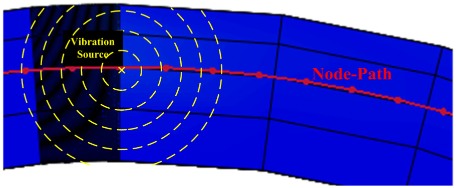
Path on the outer surface.
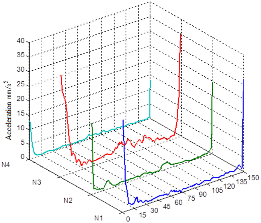
Change trend of acceleration.
In addition, the dynamic response was studied based on the N1 defect model (shown in Table 2). Along the node-path, any four nodes were selected and the node numbers in the finite element model are, respectively, 4139, 4130, 499, and 3635. The four nodes are numbered 1–4, respectively, and node 3 is corresponding to the damage location as illustrated in Figure 8. Moreover, the distances between node 3 and nodes 1, 2, and 4 are 45, 15, and 30 cm, respectively. Based on the finite element simulation, the acceleration of the four selected nodes can be extracted and the acceleration values corresponding to nodes 1–4 are, respectively, 1.7156, 8.4837, 15.3623, and 2.3799 mm/s2.

Selected node locations.
Experimental verification
In order to confirm the results obtained by FEA, a test was carried out based on the slewing bearing test table which is shown in Figure 9. The cylinder M1 and cylinder M2 are used to apply overturning moment Mt mainly and axial force Fa partly. The loading cover and upper flange also apply axial force partly by their own weight. The radial load is mainly provided by cylinder R. At last, all the loads applied to the slewing bearing are equivalent to the loads of FEA model.

Slewing bearing test table.
Furthermore, an artificial spalling defect was made on the bearing raceway surface by electrical discharge machining (EDM) as illustrated in Figure 10. The geometry size of the artificial defect was the same as the size of FEA defect model, which is shown as the first row in Table 2. The defect is small corresponding to the size of the slewing bearing whose nominal outside diameter is 1122 mm as listed in Table 1.
Spalling defect on the slewing bearing raceway surface.
During the test process, the rotational speed of the slewing bearing is set as 3 r/min to ensure that the test condition is the same as the FEA model. Due to the large size, high load, and low speed, the failure frequency is very low and the damage signal can be easily affected by noise signal. Then, a low-frequency acceleration sensor as illustrated in Figure 11 is selected to detect the failure signal. Comparing with other acceleration sensors, the resonance frequency of this sensor is very low, and this acceleration sensor is very sensitive to the low-frequency signal corresponding to the high-frequency signal. The major technical parameters are listed in Table 4.

Low-frequency acceleration sensor.
Major technical parameters of the acceleration sensor.

In order to validate the FEA results, there are also four mounting points for the sensor which are selected as illustrated in Figure 12, and the position of the selected four points is kept consistent with the position of the selected FEA nodes which is illustrated in Figure 8. The actual mounting position of the acceleration sensor is as shown in Figure 13. The vibration signal collected by the sensor in 1–4 mounting points is illustrated in Figure 14.

Sensor mounting points.
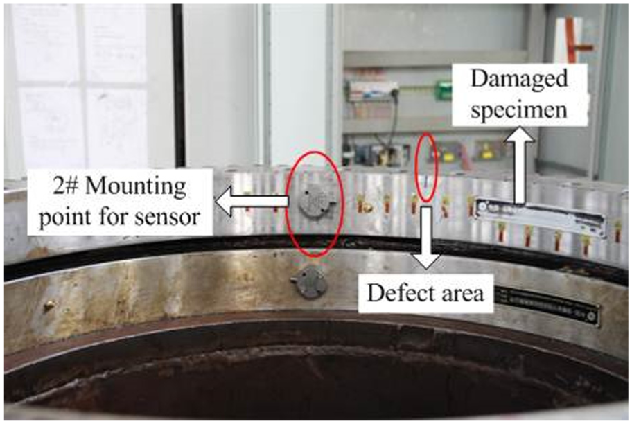
Actual sensor mounting position.

Vibration signal of mounting points 1–4: (a) mounting point 1, (b) mounting point 2, (c) mounting point 3, and (d) mounting point 4.
It is obvious that the vibration amplitude of mounting point 3 is much larger than the other three mounting points. However, the damaged signal can be easily affected by the noise signal which is induced mostly by factors such as test environment and mechanical structure. In order to extract the damage signal, the wavelet de-noising has been applied to the vibration signal processing. According to the previous research, the original vibration signal has been decomposed into seven frequency bands by the wavelet base db10. The fifth frequency band has been reconstructed by wavelet technique because the damaged signal mainly existed in this frequency band. The vibration signal after wavelet de-noising is illustrated in Figure 15.
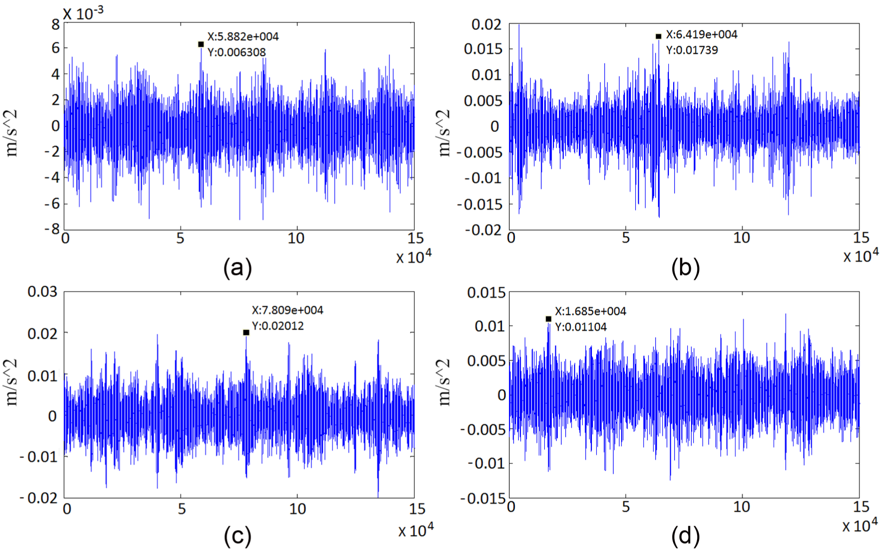
Vibration signal after wavelet de-noising: (a) mounting point 1, (b) mounting point 2, (c) mounting point 3, and (d) mounting point 4.
According to Figure 15, the vibration amplitude of the four measured points can be arranged in order of value, such as 3 > 2 > 4 > 1. It is apparent that the vibration amplitude measured in point 3 is the largest and the value is 0.0201 m/s2. The vibration amplitude of point 1 is the smallest value and it is 0.0063 m/s2. By comparing the vibration amplitudes after wavelet de-noising with the FEA results, the variation trends of test results and FEA results are consistent as shown in Figure 16. The FEA results are just relatively small. Therefore, the FEA results are reliable relatively and instructive for researching the raceway damage of the slewing bearing.

Comparison of test results and FEA results.
Conclusion
The multi-scale defects on the inner raceway surface of a slewing bearing have been created and simulated by the finite element software ABAQUS. A test for the slewing bearing with a spalling defect on the raceway has been presented. The conclusions are as follows:
The stress concentration and deformation appear on the area obviously where the rolling elements contact with the defect when the rolling elements run over the raceway. The existence of defects on the raceway surface can be identified by recognizing the pulse amplitude.
According to the comparison of changing trend of the acceleration which is induced by the four defects, it can be concluded that the length of defect is the greatest influence factor and the change of the depth has the least effect on the dynamic responses. In actual engineering, the damage propagation along the length direction should be prevented preferentially.
The results of the FEA are reliable and the analytical results obtained from the simulation provide effective theory basis for the establishment of the defect monitoring system of the slewing bearing.
Footnotes
Academic Editor: Nao-Aki Noda
Declaration of conflicting interests
The author(s) declared no potential conflicts of interest with respect to the research, authorship, and/or publication of this article.
Funding
The author(s) disclosed receipt of the following financial support for the research, authorship, and/or publication of this article: The authors gratefully acknowledge the support provided by the National Natural Science Foundation of China (51105191 and 51375222) and sponsored by QingLan Project of Jiangsu Province.