
Abstract
As fuel temperature increases, both its viscosity and surface tension decrease, and this is helpful to improve fuel atomization and then better combustion and emission performances of engine. Based on the self-regulated temperature property of positive temperature coefficient material, this article used a positive temperature coefficient material as electric heating element to heat diesel fuel in fuel pipeline of diesel engine. A kind of BaTiO3-based positive temperature coefficient material, with the Curie temperature of 230°C and rated voltage of 24 V, was developed, and its micrograph and element compositions were also analyzed. By the fuel pipeline wrapped in six positive temperature coefficient ceramics, its resistivity–temperature and heating characteristics were tested on a fuel pump bench. The experiments showed that in this installation, the surface temperature of six positive temperature coefficient ceramics rose to the equilibrium temperature only for 100 s at rated voltage. In rated power supply for six positive temperature coefficient ceramics, the temperature of injection fuel improved for 21°C–27°C within 100 s, and then could keep constant. Using positive temperature coefficient material to heat diesel in fuel pipeline of diesel engine, the injection mass per cycle had little change, approximately 0.3%/°C. This study provides a beneficial reference for improving atomization of high-viscosity liquids by employing positive temperature coefficient material without any control methods.
Keywords
Introduction
With the rapid growth of vehicles worldwide, people not only restrict its fuel consumption, but also constitute more rigid regulations to decrease vehicle emissions. Since nearly 50%–80% hydrocarbon (HC) and carbon monoxide (CO) emissions are emitted during cold start of vehicles, many countries have the regulations to test vehicle emissions at −7°C or lower.1–3 Furthermore, there is a cold start trouble on diesel engine. 4 Many researches illustrated that elevation of diesel fuel temperature not only improves cold-start emissions of engine, but also was beneficial for its cold start.2,5
Effective atomization of diesel fuel could increase the contact area with in-cylinder compressed air, fuel evaporates quickly and mixes with air extensively, and finally, there is a more complete combustion and less pollution production. There are lots of factors affecting diesel fuel atomization, such as fuel temperature, in-cylinder air temperature and pressure, fuel injection pressure and nozzle structure, and so on.6,7 Among these factors, fuel temperature is one of the most important factors, which could influence the diesel surface tension and viscosity and then affect its atomization.8,9
Yoon and colleagues10,11 investigated the relationship between fuel property and temperature that fuel density declined linearly while kinematic viscosity decreased exponentially as fuel temperature increased. Kawano et al. 12 tried to adopt experimental and numerical methods to research the effect of initial temperature on the flash boiling of multicomponent fuel, and they found that due to the evaporation of low-boiling point fuel, the spray penetration distance decreased along with the initial fuel temperature reduction. Park et al. 13 researched the relationship between fuel temperature and bio-diesel spray by experiment and simulation software KIVA-3V, and they concluded that rising fuel temperature (from 300 to 360 K) had little influence on the fuel spray penetration distance, but it had a dramatic impact on the fuel spray evaporation. The study also found that the vapor concentration of atomization increased apparently at the axial direction. With fuel temperature rising, the quantities of large diameter spray particles increased at both axial and radial directions within the selected volume, due to the rapid evaporation of small fuel particles. However, the velocities of fuel particles decreased at axial direction. Zuo et al. 14 researched the factors, such as superheated degrees of liquid, injection pressure and external environments, how to influence Sauter mean diameter (SMD) and spray cone angle, and the results showed that elevating liquid temperature could improve its atomization.
Superheated fuel is produced until its temperature is higher than the saturation temperature in corresponding in-cylinder pressure. As soon as superheated fuel is injected into the cylinder, flash boiling happens. This phenomenon is helpful for liquid atomization and mixture formation.15–17 Yamazaki et al. 18 researched the properties of flash boiling atomization of various fuels in superheated state and found that the atomization was better as fuel temperature increased, which could promote premixed combustion and shorten combustion duration, and all these resulted in a significant improvement on engine performance. Many investigations indicated that heated fuel, whether flash boiling spray happened or not, had lower viscosity and smaller surface tension, and these were beneficial for atomization and engine-emission reduction.19–21
The present methods of heating fuel could be divided into three categories, including heating fuel in tank,22,23 heating fuel in injector,24,25 and heating fuel in fuel pipeline. 26 Among these methods, the heating apparatus for fuel in tank is easy to be installed, which might utilize the waste heat from exhaust gases, 22 but it needs more heat and its heating speed is slow. Different from the above-mentioned method, heating fuel in injector needs less energy and shorter heating time, but its structure is complicated. Compared with these two methods, heating fuel in fuel pipeline has the advantages, such as its simple apparatus, appropriate energy consumption, and rapid heating speed. Some investigations employed positive temperature coefficient (PTC) material as electrical heating element for excellent heating effect, which utilized its self-regulated temperature property.23,26 The self-regulated temperature property is that within a certain temperature range, its resistivity remains constant or changes slightly; once its temperature exceeds the Curie temperature, the resistivity dramatically increases suddenly. Therefore, PTC material is regarded as a heating element without any control methods.27,28
As an important basic control element and heating element, PTC material has been extensively applied in many fields. According to the application of PTC material, it can be divided into two categories, one is the power type as an electrical heating element and other is the sensor type as a sensing element. PTC material includes polymer-based composites, high expansive ceramics, and semi-conducting ceramics29–31 Additionally, the operating temperature of PTC ceramic as heating element ranges from 0°C to 400°C.
Since using PTC material as heating element has some advantages, such as without thermostatic control or over-temperature protection, this article uses PTC ceramic to heat diesel in fuel pipeline by its self-regulated temperature property. A PTC material was specially developed and analyzed for experiments; its resistivity–temperature and heating characteristics were tested on a fuel pump bench, and the injection mass per cycle was also gauged and analyzed.
Preparation of PTC material
Based on our prior research, 26 PTC ceramic was prepared in co-operation with Haining Yongli Electrical Ceramics Co. It was a BaTiO3-based PTC material with 230°C Curie temperature, 3 × 15 × 35 mm size, 24 V rated voltage and 100 W power, as shown in Figure 1. Its surface was coated by silver for better electrical conductivity.

PTC ceramics.
The grain boundary of PTC material plays a very important role in determining the PTC effect, and therefore, its grain size needs to be critically controlled. It requires the BaTiO3 powder to have small particle size with a very narrow size distribution. In order to understand the element micrograph of developed PTC material and compositions, this study employed a JSM-5610LV scanning electronic microscope (SEM), manufactured by the Japanese Electronics (JEOL). Its fracture appearance is shown in Figure 2. The photograph shows that the compounds are substantially spherical particles with an average particle size of 4 µm in diameter.
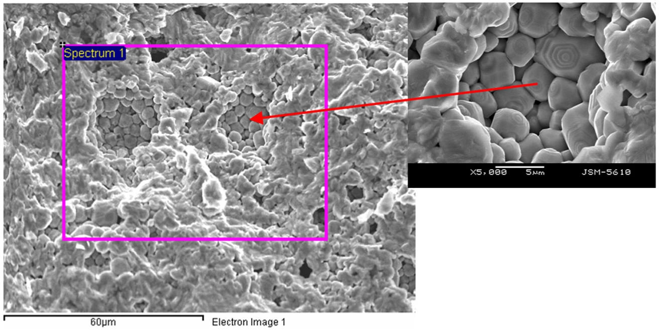
Micrograph of PTC ceramic under SEM.
This BaTiO3-based PTC material contained Si, Ca, and Pb, as shown in Figure 3 and Table 1. Since the pure BaTiO3 is an insulator and its room temperature resistance is very high, doping semi-conducting additive Si in BaTiO3 improves its conductivity. Adding Ca and Pb makes BaTiO3 having a proper Curie temperature for this study.
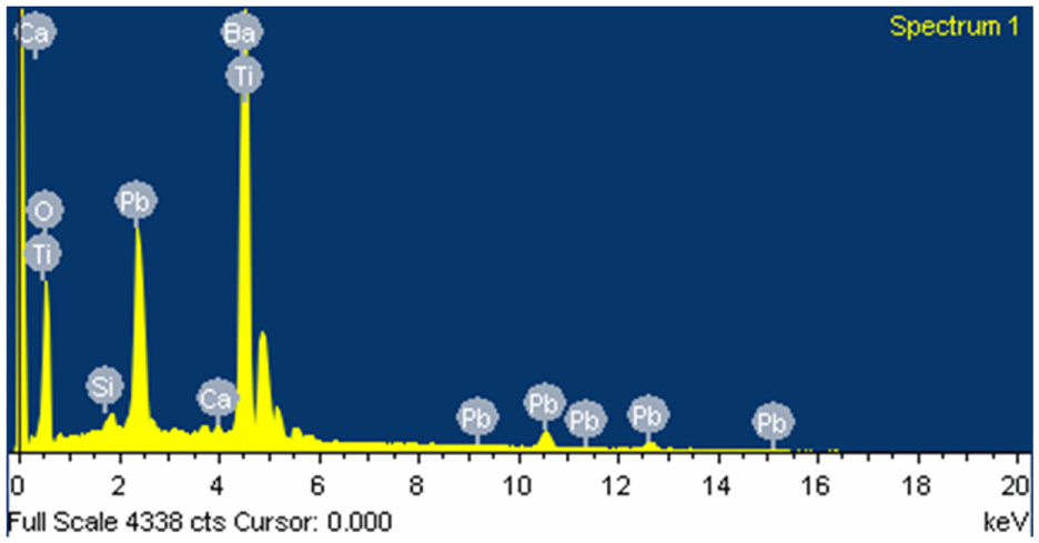
Energy spectrum of PTC material.
Elementary compositions of PTC material.

Experimental equipments and procedure
Experimental equipments
The schematic diagram of experimental apparatus is illustrated in Figure 4, and its picture is shown in Figure 5. The test system mainly consisted of a fuel pump bench, fuel pump, injector, DC stabilized power supply, temperature sensors, data acquisition system, and an electrical balance. The experiments were completed in the LBD860-075 fuel pump bench, manufactured by Shandong Rabotti Experiment Equipment Co. A BH4Q85-65-85-R8 fuel pump was selected, which was made by Shandong Kangda Group Co. The fuel pump bench is able to provide different rotating speeds for the fuel pump so as to adjust the diesel flowrate in fuel pipeline. The mechanical injector with 210 bar injection starting pressure was made by Longkou Hongchang Mechanical Manufacture Co. in which type KBAL-P028 was modified with a 0.3 mm diameter nozzle.
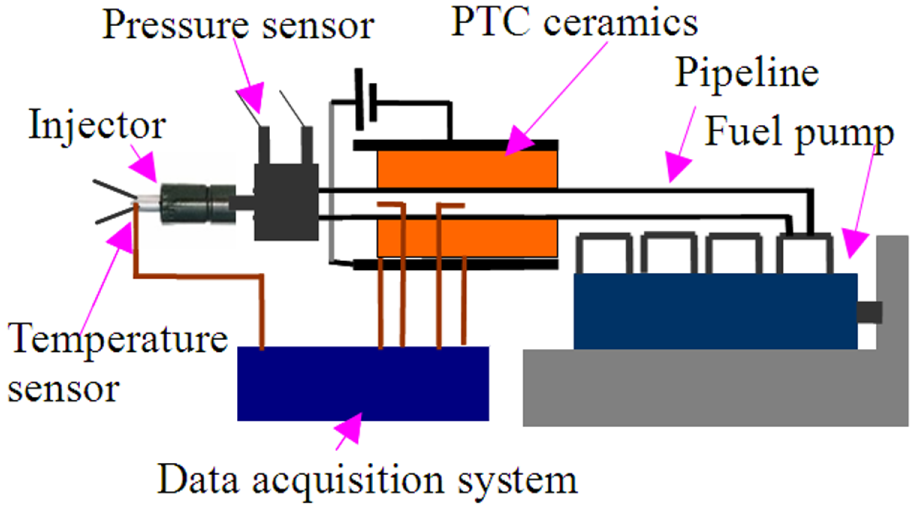
Schematic diagram of experimental apparatus.
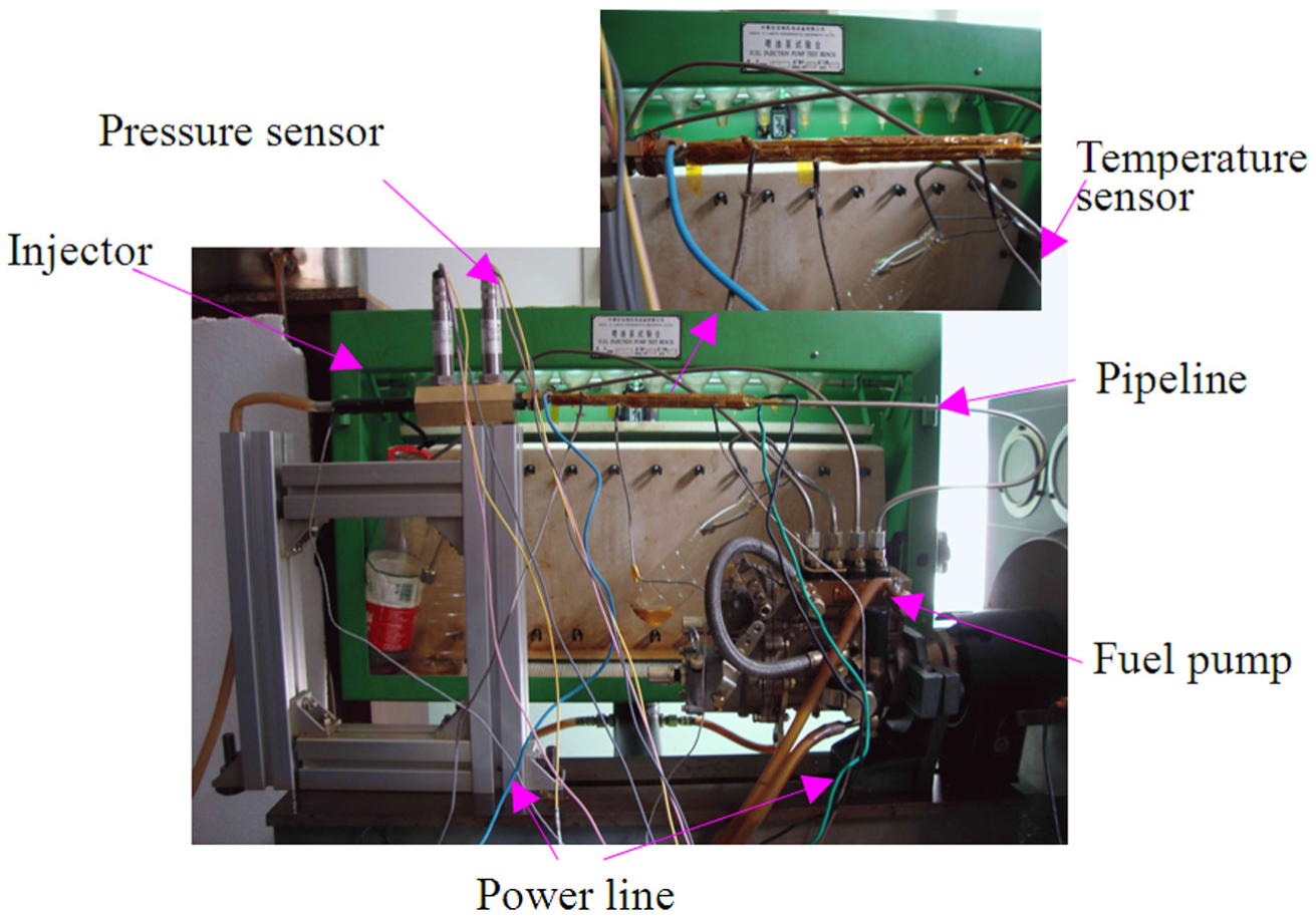
Picture of experimental apparatus.
In experiments, six PTC ceramics were installed on the surface of fuel pipeline with three pieces each side, and the length of wrapped pipeline was 10.5 cm, as shown in Figure 5. The measuring temperature points on the surfaces of fuel pipeline and PTC ceramics are shown in Figure 6. Point A and point B were located at the surface of fuel pipeline, and point C and point D on the surface of PTC ceramics. The distance from point A to point B was 5.25 cm as same as that from point C to point D.
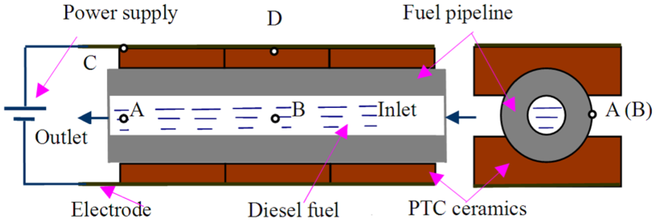
Schematic diagram of PTC ceramics installed on pipeline.
An APS3005Si power source with digital display was employed as the DC stabilized power supply for PTC ceramics, produced by Beijing Art Technology Development Co. This stabilized power source has a high-precision single output voltage and current, which could be continuously adjusted and automatically switched between constant voltage and constant current (CV/CC), and its output range is 0–30 V and 0–5 A. Six K-type thermocouples were used as the temperature sensors in which measuring range is 0°C–300°C with ±1°C measuring error and 0.3 s response time. Before measuring, these thermocouples were calibrated under 25°C environment temperature by a Fluke 9173 Metrology Well. The data acquisition system was a DAM-3000M data acquisition module with an eight-channel acquisition card, 10 Hz sampling frequency, and 0.1% accuracy, made by Beijing Art Technology Development Co., while its operating temperature is −30°C to 80°C. The injection fuel mass was weighed by a LT10KA-1 electrical balance, which is fabricated by Changshu Tianliang Instrument Co., and its weighing scope is up to 10 kg while its accuracy is 0.1 g. As indicated in Figure 4, two pressure transducers installed between the heated section and the injector for detecting the differential pressure signals would be employed to identify fuel flow-pattern intelligently for future research.
Test fuel
Commercial number zero diesel oil was bought from market (National Standard of China GB17147-2009) whose physical and chemical properties are shown in Table 2.
Physical and chemical properties of number zero diesel fuel.

Test procedure
In experiments, the total resistance R of six PTC ceramics was tested first; then the temperature changes of PTC material, heated fuel pipeline, and injection fuel were recorded, and the injection mass per cycle was also gauged.
The equivalent-circuit diagram of six PTC ceramics is shown in Figure 7. A self-made bleeder circuit was made to measure the total resistance R of PTC ceramics.

Acquisition principle diagram of resistance R of PTC ceramics.
The total resistance R of PTC ceramics and fixed value resistance R1 were connected in series and supplied by the stabilized power supply V0. The voltage V1 was recorded every 1 s. Therefore, the total resistance R of six PTC ceramics is calculated as

Under 15, 20, and 24 V power supplies, the temperature changes on the surface of fuel pipeline were measured as the fuel pump was not started up. This aim was to evaluate the heating speed of PTC ceramics and heating capacity under different power supplies. As the fuel pump was in operation, the temperature changes of fuel pipeline and PTC ceramics were read under suitable power supply.
With the rotating speeds of fuel pump as 200, 300, and 400 r/min and preheating times as 10, 15, and 20min, the injection fuel temperatures were recorded and analyzed. At last, the injection fuel mass per cycle was checked and compared under the conditions of different equilibrium temperatures and room temperature.
Experimental results and analysis
Temperature–time and resistivity–temperature characteristics of PTC ceramics
Under 15, 20, and 24 V power supplies, the temperature–time and resistance–temperature characteristics of PTC ceramics were recorded at point D, as shown in Figures 8 and 9, respectively. The temperature of PTC ceramics could reach the equilibrium temperature under different voltages, which had different heating durations, such as 100 s for 24 V while above 300 s for 15 V. Notably, under 20 and 24 V power supplies, there was a shorter heating duration for arriving at the equilibrium temperature than under 15 V power supply. Figure 9 indicates that there were similar resistance–temperature features under different power supplies, and its minimum resistance was 8.12 Ω. The higher the power supply was, the shorter the heating time was. Before the temperature of PTC ceramics arrived at 170°C, the higher the power supply was, the smaller the heating resistance was. But after 170°C, the tendency was contrary. However, as the temperature of PTC heating elements exceeded the equilibrium temperature nearby, the resistance increased sharply.

Temperature–time curves of PTC ceramics as different power supplies.

Temperature–resistance curves of PTC ceramics as different power supplies.
The formula of heating power of PTC elements is listed as

where P is the heating power, V0 is the power voltage, R is the resistance of PTC ceramics, D is the dissipation coefficient, T is the temperature of PTC ceramics, Tamb is the ambient temperature, and V0 and D are the fixed values. According to formula (1), as the PTC ceramic resistance R rising, both the power P and temperature T decrease. Once the temperature T decreases, the resistance R is also descending, and this results in the power P rising, and then the temperature T is also increasing. This is the self-regulated temperature effect of PTC material. As shown in Figure 9, under 24 V power voltage, the resistance of PTC ceramics changed most rapidly, this is to say, it needed a shorter time to adjust the equilibrium temperature. Compared to 15 and 20 V power supplies, 24 V power supply was more suitable for heating diesel in fuel pipeline to a new equilibrium temperature as soon as its flowrate changed (i.e. the rotating speed of fuel pump was adjusted).
In order to understand how the resistance of PTC ceramics changed with the fuel flowrate changing, an experiment was completed as shown in Figure 10. After 400 s heating duration under 24 V power supply, the resistance remained 8.12 Ω. In fact, this is due to the self-regulated temperature effect. In Figure 9, the initial temperature of PTC is about 25°C, and its resistance is about 15 Ω. After 400 s heating duration under 24 V power supply, its temperature rose up to the equilibrium temperature, and the resistance dropped down to 8.12 Ω. Then starting up the fuel pump for getting a certain fuel flowrate, the total resistance of PTC ceramics fluctuated anxiously. The reason was that PTC ceramics adjusted its resistance consistently so as to achieve the self-regulated temperature effect.

Resistance of PTC ceramics as fuel pump operating.
Variation and analysis of fuel pipeline temperature
Figures 11–13 show the temperature changes at point A and point B under different power supplies as the fuel pump is not started up. Under 15, 20, and 24 V power supplies, the equilibrium temperatures at point A were 168°C, 182°C, and 175°C, and the equilibrium temperatures at point B were 180°C, 193°C, and 185°C, respectively. Since point B was located at the middle of heated section of fuel pipeline, the equilibrium temperature was higher than at point A. In the view of these equilibrium temperatures, it was found that the equilibrium temperature differences at point A and point B were almost same, approximately 12°C, 11°C, and 10°C, respectively.

Temperatures of fuel pipeline as 15 V power supply.

Temperatures of fuel pipeline as 20 V power supply.

Temperatures of fuel pipeline as 24 V power supply.
It was interesting that not under 15 or 24 V power supply, but under 20 V power supply, there was a higher equilibrium temperature regardless of at point A or at point B. This could be explained from Figure 8. From this temperature–time characteristic chart, the equilibrium temperature was 225°C at 20 V power supply, while the equilibrium temperatures are 220°C and 212°C at 24 and 15 V power supplies, respectively. So, the higher heat source under 20 V power supply would result in the higher temperature at the surface of fuel pipeline. Of course, this might be explained through PTC microstructure and so on.
In order to understand the process of heating fuel pipeline by PTC ceramics, three stages were divided as the rapid heating duration, slow heating duration, and constant heating duration, as shown in Figure 11. In the rapid heating duration, the heating speed was most rapid, while in the constant heating duration, the temperature was constant.
For comparing their heating speeds, the temperature rising rate α1 in the rapid heating duration is defined as

where O is the initial heating time, E is the turning time from the rapid heating duration to the slow heating duration, TE and TO are the temperatures at E time and O time, respectively, and ΔtEO is the rapid heating duration from O time to E time.
The temperature rising rate α2 in the slow heating duration is defined as

where F is the turning time from the slow heating duration to the constant heating duration, TF is the temperature at F time, and ΔtFE is the slow heating duration from E time to F time. Notably, the location of E or F is determined by the error of α1 or α2, which is less than 5%. That is to say, the uncertainty of the location of E or F is less than 5%.
Under 15, 20, and 24 V power supplies, the rapid heating durations ΔtEO were 600, 350, and 200 s, while the slow heating durations ΔtFE were 700, 125, and 100 s, respectively. With the increasing power supply, both the rapid heating duration ΔtEO and the slow heating duration ΔtFE decreased. Under 20 and 24 V power supplies, there were small differences in ΔtEO and ΔtFE, especially in ΔtFE. In order to compare the temperature rising rates at point A and point B, α1 and α2 were computed in Table 3.
Comparisons of α1 and α2 at point A and point B.
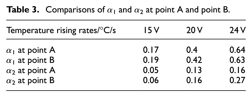
As shown in Table 3, both α1 and α2 were going up with the power supply increasing. The temperature rising rate α1 at point A was up to 0.64°C/s under 24 V power supply, approximately four times under 15 V power supply. Under the same power supply condition, the temperature rising rates α1 at point A and point B were similar. At the same position and power supply conditions, the value of α1 was approximately three times as that of α2. In the views of the equilibrium temperature and heating speed, the power supply should be selected 24 V rated voltage for this PTC ceramic.
In order to consider the temperature changes of fuel pipeline and PTC ceramics as the fuel pump was in operation (note diesel fuel in pipeline was fluctuating), an experiment was conducted. Before testing, PTC ceramics was in operation by 24 V power supply so as to preheat fuel pipeline up to the equilibrium temperature. Then, the fuel pump started up at 200 r/min. The temperatures of fuel pipeline and PTC ceramics were recorded under 24 V power supply, as shown in Figures 14 and 15.

Temperatures of fuel pipeline.
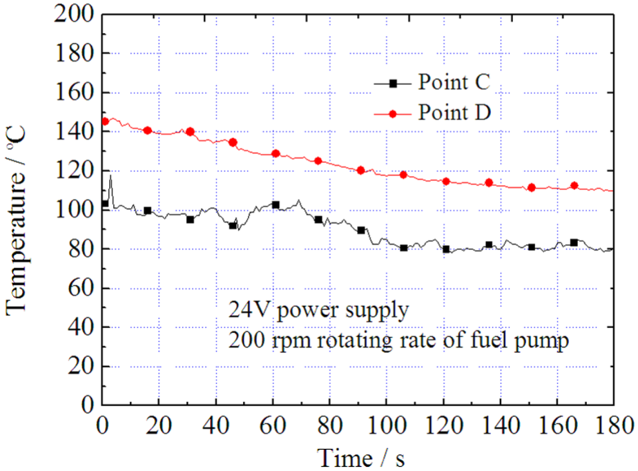
Temperatures of PTC ceramics.
With the fuel pump starting up, the temperatures at point A and point B were declining down to new equilibrium temperatures. From the temperature of fuel pipeline, as shown in Figure 14, there was somewhat sluggish for several seconds to heat fuel pipeline due to consuming time for heat conduction. The temperature at point B descended more quickly than at point A, and the cause was that due to diesel fuel flowing from point B to point A, its temperature increased gradually, and the consuming heat at point A was less than at point B. Therefore, the equilibrium temperature at point B was lower.
With the fuel pump starting up, the temperatures at point C and point D were also declining down to new equilibrium temperatures. From the temperature of PTC ceramics as shown in Figure 15, there was a slow fall within 3 min. Due to point D positioned at the middle of heating section, more heating energy improved and balanced the temperature at point D, its temperature was higher than the temperature at point C, and its fluctuation is also more gentle.
Variation and analysis of injection fuel temperature
According to the analysis of above results, the power supply should be selected for 24 V as measuring the injection fuel temperature. With the rotating speeds of fuel pump at 200, 300, and 400 r/min and preheating times at 10, 15, and 20 min, respectively, the injection fuel temperatures were gauged, illustrated in Figures 16–18. Notably, during preheating diesel fuel, the fuel pump did not start up so as to the temperature of diesel fuel in pipeline could reach an equilibrium temperature. Certainly, the temperature of fuel pipeline also achieved a balance.

Temperature of injection fuel.

Temperatures of injection fuel.

Temperatures of injection fuel.
It could be seen that under the above experimental conditions, the injection fuel temperatures could all be promoted in the range of 21°C–27°C within approximately 100 s and then kept constant. Under 200, 300, and 400 r/min conditions, the rapid heating durations were 32, 29, and 28 s, while the slow heating durations were 52, 34, and 27 s, respectively. With the rotating speeds of fuel pump increasing, both the rapid heating durations and the slow heating durations decreased. There was a small difference for the rapid heating durations, but the difference was apparent for the slow heating durations. During the rapid heating duration and slow heating duration, the fuel filled in the pipe between the wrapped section of pipeline and the injector was injected first, so its temperature was lower than the equilibrium temperature. As indicated in formula (2), the ambient temperature would have influence on the temperature of heating section, and then on the temperature of heated fuel. When the PTC elements are working on a much higher temperature, the effect of the ambient temperature might be minor. It must be pointed out that the pump’s work will generate heat to warm the fuel up, and this makes a contribution to the fuel’s temperature increase. Under the condition of 400 r/min pump speed, the test showed that the most fuel’s temperature increase due to the pump’s energy was less than 0.9°C. In order to compare the temperature rising rates under different rotating speeds of fuel pump and different preheating times, α1 and α2 were computed as shown in Table 4.
Comparisons of α1 and α2.

Under the same preheating time condition, the temperature rising rate of injection fuel increased with the rotating speed of fuel pump going up, while its equilibrium temperature decreased. The reason might be that with the rotating speed of fuel pump rising, the heating time for diesel was shortened, which lowered its equilibrium temperature. Meanwhile, the high rotating speed of fuel pump was helpful for the heated fuel accomplishing injection. For example, with 10 min heating duration, values of α1 were rising from 0.44°C/s to 0.52°C/s, while values of α2 were decreasing from 0.14°C/s to 0.09°C/s. However, under different rotating speeds of fuel pump and different preheating times, α1 was in the range of 0.44°C/s–0.61°C/s.
Moon et al. 20 investigated the influence of injector temperature on combustion and emission characteristics of engine, and they found that during the first 200 cycles as the engine speed was 200 r/min, the concentrations of particulate matter and total HC all decreased with fuel temperature rising, but CO concentrations appeared to be first increasing and then decreasing with fuel temperature going up. Tan et al. 32 researched cold-start emissions of diesel fuel car in real world and disclosed that total HC and nitrogen oxide (NOx) emissions produced during warm start were less than during cold start, and the fuel consumption was also fewer.
Analysis of injection fuel quantity
According to Figure 16, as the rotating speeds of fuel pump were 200, 300, and 400 r/min, the equilibrium temperatures of injection diesel fuel were approximately 49.5°C, 48.5°C, and 46°C, respectively. Injection fuel mass per cycle was checked and compared under the conditions of preheating for 10 min and about 25°C room temperature, as shown in Figure 19. With the rotating speed rising, the injection fuel mass per cycle was increasing apparently. At the same rotating speed of fuel pump, there was more injection fuel quantity at room temperature condition than at equilibrium temperatures by PTC ceramics heating. The temperature influence on the injection fuel mass per cycle was approximately 0.3%/°C. Dernotte et al. 33 argued that fuel density and fuel viscosity affected the discharge coefficient and fuel injection rate. High fuel temperature lowered fuel density and fuel viscosity, so this decreased the injection fuel mass per cycle.
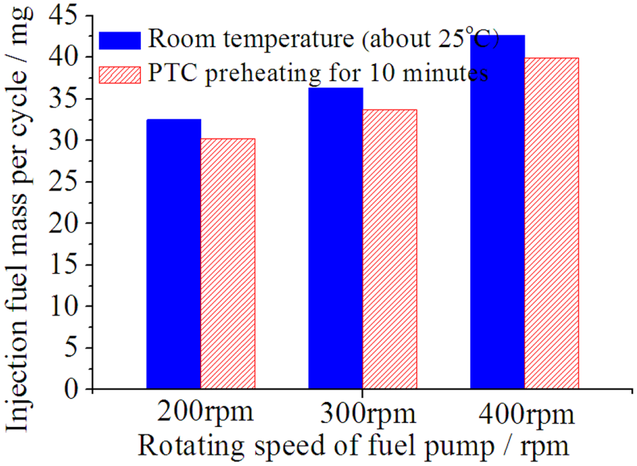
Comparison of injection fuel mass per cycle.
Conclusion
In this article, the experiments of using the PTC material to heat diesel in fuel pipeline of diesel engine were conducted. The resistivity–temperature characteristics of BaTiO3-based PTC material were tested and analyzed. On a fuel pump bench, its heating characteristics were understood, and the injection fuel mass per cycle was also tested and compared. The obtained conclusions are as follows:
The PTC material with 230°C Curie temperature and 24 V rated voltage is prepared for the experiment. Employing it to heat diesel in fuel pipeline provides an effective method on controlling diesel temperature.
Compared to other power supplies, the rated power supply is more suitable for heating speed and heating capacity. Under the rated power supply, there are more rapid heating speed and more suitable equilibrium temperature.
The fuel temperature improvement is in the range of 21°C–27°C in 100 s, and then the fuel temperature remains unchanged.
Using the PTC material to heat diesel in fuel pipeline of diesel engine, the injection fuel mass per cycle has little change. The temperature influence on the injection fuel mass per cycle is approximately 0.3%/°C.
As a kind of smart heating element without any control methods, PTC material can provide a beneficial choice for improving atomization of those high-viscosity liquids.
Footnotes
Acknowledgements
Dr Lao Liyun of School of Energy, Environment and Agrifood, Cranfield University is thanked for his help in discussion and revision of the article. Professor Wang Lan of Key Laboratory of Advanced Textile Materials and Manufacturing Technology, Ministry of Education, Zhejiang Sci-Tech University is also acknowledged for analysis and discussion of micrograph and compositions of PTC material.
Academic Editor: Jose Ramon Serrano
Declaration of Conflicting Interests
The author(s) declared no potential conflicts of interest with respect to the research, authorship, and/or publication of this article.
Funding
The author(s) disclosed receipt of the following financial support for the research, authorship, and/or publication of this article: This work is supported by the Zhejiang Province Natural Science Funds, P.R.C. (LY14E050023), and authors also acknowledge Haining Yongli Electrical Ceramics Co. for preparation of PTC ceramics.