
Abstract
Two-phase cavitating flow in the diesel nozzle has been widely concerned by researchers for a long time. Most of the attention has been paid to irregular geometry-induced cavitation, while the research on string cavitation induced by vortex is relatively less. The two cavitating patterns often occur simultaneously in the nozzle, which are still not understandable for their interaction characteristics. In this paper, it is analyzed that the characteristics of string cavitation and geometry-induced cavitation in the transparent nozzle based on the visual scale-up test bench. In the study of hole-to-hole string cavitation, it is found that when needle lifts elevate, geometry-induced cavitation and hole-to-hole string cavitation are observed all together under the same working condition. The development and stability of hole-to-hole string cavitation are further improved with the increase of fuel temperature. The geometry-induced cavitation and string cavitation interact with each other, that is, geometry-induced cavitation at the nozzle inlet interrupts the hole-to-hole string cavitation inception. The tail of hole-to-hole string cavitation is disturbed by cloud cavitation shedding after its developing into the nozzle hole, leading to fracture in serious cases. At high temperatures, there is a periodic transformation between the needle-originated string cavitation and hole-to-hole string cavitation.
Introduction
Fuel economy and emission cleanliness have gradually become the primary factors to be considered in diesel engine with proposing the concept of “energy saving” and “environmental protection.”1,2 The electronic high-pressure common rail fuel injection system is equivalent to the “heart” and “brain” of the internal combustion engine, and is regarded as a landmark technology to improve fuel economy and reduce pollutant emissions.3,4 Injector nozzle is the most critical core component in high-pressure common-rail fuel injection system,5–7 which is related to the accuracy and stability of fuel injection system. Cavitation phenomenon performs the most common two-phase flow in the nozzle with high turbulence and strong compression. 8
Cavitating patterns present significantly dissimilarity under different fuel conditions and developing stages. The cavitation phenomenon is often caused by the flow shrinkage and the wall backflow low-pressure zone, and then further extends to the nozzle outlet, which is called geometry-induced cavitation. 9 And another type of linear cavitation (string cavitation) is led to the strong vortex in the flow and the central low-pressure region. 10 Researchers have carried out extensive studies on the two cavitating patterns.
Among them, the most common affecting factors are geometric structure, such as hole inclination angle, 11 hole shape,12,13 SAC volume structure 14 and needle lift. 15 The vortex structure in the diesel nozzle were observed under the constant needle lift and flow rate.16–18 It is generally believed that injection pressure 19 and back pressure 20 belong to the category of hydrodynamic factors. With the research deepening, the factors of needle valve movement are also gradually classified into this category. 21 The research focuses on the promotion and restriction of injection pressure and back pressure on cavitation patterns, as well as cavitating flow in each nozzle hole with needle valve eccentricity.22,23 The medium factors of cavitation two-phase flow mainly include two aspects: gas content 24 and physical properties. 25 Research methods for adding gas content through ventilation operation are mostly focused on hydraulic machinery such as hydraulic turbine, which is to suppress cavitation erosion and reduce flow resistance.26,27 And the effect of air flow on vortex structure and the effect on improving flow pattern are studied based on numerical simulation methods in diesel nozzle. Suppressing cavitation erosion and promoting spray atomization can be achieved by the ventilation operations within diesel nozzles.
There are few researches on fuel properties, especially fuel temperature in the diesel nozzle, and accurate control of fuel temperature is a technical problem to be solved. During the single injection period, fuel needs to flow through the tank, common rail, injector and other components. The temperature loss along the way is difficult to control.28,29 The fuel temperature in the nozzle changes with the diesel engine operating, which ranges from 0°C to 150°C. 30
The substantial temperature change affects the physical parameters such as saturated vapor pressure, viscosity and density, and then affects the flow characteristics and spray combustion process in the combustion volume.31–33 Therefore, the research on fuel temperature has its unique practical significance. The researchers analyzed the evaporation of the liquid bubble during the liquid growth from the cavitating thermodynamic effect, resulting in a phase change latent heat such that liquids near the two-phase regions. 34 Furthermore, as the injection pressure increases due to the local pressure reducing, the swelling effect of diesel fuel affects the temperature change in the two-phase. 35 Then the huge shear force on the nozzle wall causes a viscous heating effect, leading to an increase in enthalpy and fuel temperature. Specifically, the greater the injection pressure develops, the more obvious change of fuel temperature reaches in the nozzle. 36 When the fuel temperature at the injector inlet exceeds the critical value, the fuel is super-cooled in the steady-state injection phase, while below the critical value causes laminar or transitional flow states, resulting in significant fuel heating. The investigation of near-field spray characteristics shows that spray droplet size increases in both axial and radial directions with fuel temperature increasing, accompanied by the deterioration of fuel evaporation characteristics.37,38
In general, most of the current researches on fuel temperature factors focus on energy conversion at the micro scale, and a few focus on near-field atomization, while the atomization effect is directly limited by the cavitating two-phase flow characteristics inside the nozzle hole. Unfortunately, it is rare to explore the relationship between fuel temperature and cavitation in the hole. 39 Based on the basis of previous studies, 40 the occurrence and development of geometry-induced cavitation and string cavitation at different fuel temperatures and special cavitating phenomena were comparatively studied in this paper. The data obtained are rich and reliable in the experimental study, providing real and effective data support for cavitating model and atomization mechanism, and providing a brand-new theoretical background for the new generation of high hydraulic and mini-type injector.
Experimental setup and methodology
Facilities and fuel
Based on the experimental platform with internal flow and spray atomization of high pressure common-rail nozzle, the paper takes the diesel nozzle processed with polycarbonate transparent material as the research object, and carries out the visualization of cavitating structure in the diesel nozzle considering the injection pressures and fuel temperatures. The actual size of the transparent nozzle is only about 0.2 mm, combined with the high fuel velocity, which is difficult to capture the transient cavitating conditions inside the nozzle. Based on this, the origin-size nozzles are scaled up to 10 times, according to the flow similarity principle, which tends to clearly capture cavitating structures and precisely control critical geometries. It should be noted, the Reynolds number becomes exact to the greatest extent in the enlarged nozzle under the premise in geometric similarity, given that not all parameters (Strouha number, Reynolds number Euler number, Froude number) can be considered.
Figure 1 shows the visualizing test platform of the transparent nozzle in 10 times scale-up platform. The injection pressure is adjusted to the test pressure of different working conditions by adjusting the pressure-control valve on the pipeline. When the injection pressure is stable, the cavitating flow and spray structures are recorded in real time by high-speed digital camera and LED light source (the nozzle is placed between high-speed digital camera and LED light source). The diesel fuel from the nozzle hole is collected by the fuel receiving tank, and all the fuel in the regulator tank is recovered to the fuel receiving tank, completing a working cycle. The diesel fuel is required to be heated in the test, and the heating device is an electric heating tube mounted in the fuel receiving case bottom. To reduce heat loss during this time, the pipeline and the pressure regulator tank are insulated. The temperature difference between the fuel tank and the upstream pipe of the nozzle reaches 6°C after calibration. Different fuel temperatures are obtained through a touch thermometer. The screen display on the temperature gets a stable temperature value after the stylus placed in the center of the fuel for about 10 s. Therefore, the temperature involved in the test analysis is subject to the temperature of the upstream pipeline. The main setting parameters are as follows: frame rate (20,000 frames), spatial resolution (2.7 μm) and resolution (1024 × 1024). Experimental parameters shown in Table 1. The physical property parameters of diesel fuel also shows significant differences at different temperatures, and the main physical parameters affecting cavitation phenomena are listed in Table 2.

Experimental schematic of the visualization system in diesel nozzle.
Features of diesel fuel and experimental cases.

Physical property parameters of diesel fuel at three temperatures.

Optical nozzle tips
Transparent nozzles are made in two ways: 3D printing and high-precision machining. In particular, the external profile of the nozzle is obtained by high-precision machining, while the internal dimensions such as the SAC volume and the inlet rounded corners are obtained by the former. The geometric dimensions are shown in Table 3.
Parameters of the nozzle.

The typical image and post-processing methodology
The original image is obtained by the shadow method in Figure 2. The gas phase of the cavitation region prevents light from passing through freely, so that the corresponding region on the camera appears black. Since the fuel and the nozzle material keeps similar refractive index (The refractive indices of both are 1.44–1.47 and 1.49, respectively), light passes through the fuel area freely, which is white in the original image.

The sample graph of cavitating flow with shadow method.
Matlab software is used to independently write a post-processing solution program to extract the specific data information (cavitation intensity, spray angle, etc.) in the original image. Taking string cavitation as an example, string cavitation intensity (Istring) is defined as follows:

Sstring represents the cross-sectional area of cavitation in the hole, and Shole represents the area of the hole in a two-dimensional image. The cross-sectional area corresponds to the area in the plane defined by injector axis and orifice axis. The hole area is obtained from the diameter and length, and the area of string cavitation is to be solved. As shown in Figure 3, First, select the region to be solved (I). A blank image without fuel injection is saved as the background image before each test (II). Then in the loop program, the blank background image is used to subtract the cavitating image at different time successively (III). The image after superposition is treated by binarization, that is, the string cavitation region (IV) in the hole is obtained.
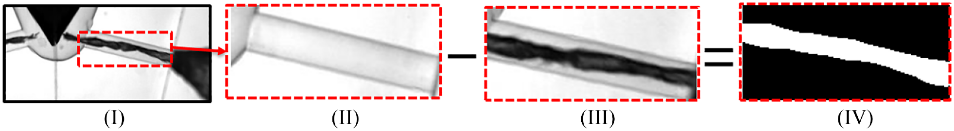
Post-processing for string cavitation intensity: (I) Processing area, (II) Image without cavitation, (III) Image with cavitation, and (IV) The binary image.
Results and discussion
The cavitation inception under different fuel temperature conditions
The pre-test data found that when two cavitating patterns coexist, the needle-originated string cavitation occupies absolute dominance, while geometry-induced cavitation achieves insufficient development. The needle-originated string cavitation inception can be considered as a fully-developed form of hole-to-hole string cavitation. When the vortex intensity in the nozzle remains weak, the vortex region where the string cavitation locates is in the SAC volume, forming the hole-to-hole string cavitation. After strengthening the vortex intensity in the nozzle, the vortex region runs through the entirety nozzle hole, and the low-pressure region in the center of the vortex region meets the condition of cavitation inception, forming a coarse needle-originated string cavitation extending out of the nozzle hole. At this time, even if there is a weak gas core at the hole inlet that induces a small range of geometry-induced cavitation, the gas core can be sucked up and converged to the center of the vortex under the effects of strong eddy current, transforming geometry-induced cavitation to string cavitation. Therefore, the inception and interaction of two cavitating patterns are investigated between them.
Figure 4 shows the inception and development of two cavitating patterns at different temperatures and 1.5 mm needle lift. At room temperature, the flow pattern is single-phase flow in the hole at 0.10 MPa injection pressure, and there is neither geometry-induced cavitation nor hole-to-hole string cavitation. It belongs to the early preparation stage for cavitation inception at this time. The injection pressure still persists low with limited growth rate of eddy current strength, and the pressure is slightly lowered in the vicinity of the inner axis. The vicinity of the fuel saturated vapor pressure is always uneven that leads to hole-to-hole cavitation occasionally disappearing. Therefore, it is achievable to observe the cavitation patterns (0–0.9 ms, 0.15 MPa) in the development stage of the hole-to-hole cavitation in the original image. However, no geometry-induced cavitation is observed except for the unstable hole-to-hole cavitation at the 0.15 MPa injection pressure. So far, two cavitation patterns present obvious divergences. In other words, hole-to-hole string cavitation occurs firstly and initiates easier at low injection pressures. Geometry-induced cavitation is observed on the upper wall of the nozzle as the injection pressure increases to 0.25 MPa. At this time, the primary geometry-induced cavitation occurs more unstable than the hole-to-hole cavitation. Subsequently, the geometry-induced cavitation is observed on the upper wall of the nozzle at 0.25 MPa, and the primary geometry-induced cavitation presents additional instability compared with the hole-to-hole cavitation, which is entrained by the upstream fuel toward the nozzle outlet and then re-generates the new one in the original area. In a single injection condition, it can be observed that the change presents a periodicity.

Comparative study on the inception characteristics of two cavitating patterns at different temperatures (h = 1.5 mm).
When the fuel temperature rises to 40°C, the hole-to-hole string cavitation occurs at the 0.10 MPa injection pressure, while the geometry-induced cavitation initiates at 0.20 MPa. The injection pressure of two cavitating patterns decreases with the increase of fuel temperature, which is similar to the previous discussion, mainly due to the increased fuel saturated vapor pressure and reduced viscosity with temperatures, which reduces the requirement of cavitation inception.
It should be explained that the reason why hole-to-hole cavitation is easier to be generated is determined by the special structure of vortex flow field where string cavitation locates. The convergence effect of the vortex flow field converges the free gas to the center of the vortex and bind it inside, then the low-pressure region in the center of the vortex provides the premise for cavitation inception. The adsorption of free gas in the surrounding area by vortex flow field on the one hand affects the decreasing trend of pressure in the geometry-induced cavitation region, and on the other hand changes the distribution of gas core in the geometry-induced cavitation region, thus leading to the hole-to-hole cavitation inception under the similar conditions.
Interaction characteristics of two cavitation patterns
For the two cavitation patterns discussed in this paper, geometry-induced cavitation and string cavitation, the strong swirling flow in the nozzle makes the cavitation pattern appear as the needle-originated string cavitation under low needle lifts and high injection pressures, and there is only one cavitation pattern in the nozzle. As the needle lift enlarges, geometry-induced cavitation begins to occur, and the two cavitation patterns exist simultaneously. Due to the micro-scale characteristics of the nozzle, the positions of two cavitating patterns bound to be close to each other, which inevitably interact each other. At the low injection pressure in Figure 4, the vortex strength in the hole persists fragile, and the hole-to-hole cavitation seems stable. Figure 5 shows the specific coexisting situation of cavitating patterns as the injection pressure increases to 0.35 MPa.

Development characteristics of two cavitating patterns coexisting at room temperature (h = 1.5 mm, Pinj = 0.35 MPa).
Under this condition, cavitating shedding phenomenon (cloud cavitation) always exists at the tail of geometry-induced cavitation. The cloud cavitation after shedding develops with the fuel toward the hole outlet (0.25 ms-partial enlarged drawing). The pressure environment gradually recovers during cavitation developing, that is, the pressure near the hole outlet rising, basically returns to the normal situation. Therefore, cloud cavitation tends to collapse at this time (0.35 ms-local enlargement). However, its own pressure is still relatively low, which has an attractive effect on the hole-to-hole cavitation. The huge energy is released during the cloud cavitation collapsing, and the generated pressure shock wave disturbs the hole-to-hole cavitation tails attracted to the adjacent area, resulting the fracture (2.15 ms-local magnified image). The part of the fracture evolves into cloud cavitation, which is similar to the cloud cavitation that falls off from geometry-induced cavitation, and then collapses at the hole outlet after the same process (2.2 ms-partial enlargement). This phenomenon strengthens the effect on the hole wall, thus aggravating the cavitation erosion of the nozzle wall. The vortex region where the hole-to-hole string cavitation locates is not affected by the collapse. Similar to geometry-induced cavitation, new string cavitation still generates after the tail fracturing, indicating that the effect is transient produced by the cloud cavitation collapse.
In addition, the presence of geometry-induced cavitation at the nozzle wall surface also has a significant effect on the hole-to-hole cavitation inception. The initial position of the hole-to-hole cavitation is usually at the hole inlet. It begins to accelerate to the downstream and finally reverses into the SAC volume to connect the two holes After growing slowly to a certain length. In other words, if the structure destroys at the beginning, it will not have the opportunity to continue to grow and develop. As shown in Figure 6, hole-to-hole cavitation is immediately adsorbed near geometry-induced cavitation area on the upper wall (0.1 ms) after occurring at 0 ms. Finally, it is destroyed and dissipated in its periphery (0.3 ms) before entering the interior of the geometry-induced cavitation region. It should be noted that the phenomenon of position shift caused by string cavitation being attracted under the action of low pressure has little effect on the vortex region where string cavitation originally locates.

Effect of geometry-induced cavitation on hole-to-hole string cavitation inception at room temperature (h = 1.5 mm, Pinj = 0.35 MPa) .
As shown in Figure 7, when the fuel temperature increases, the stability of hole-to-hole cavitation is enhanced with the maintained time significantly prolonging in the SAC volume (hole-to-hole cavitation often cannot penetrate the SAC volume at 20°C). From the perspective of cavitation region, both the geometry-induced cavitation and hole-to-hole string cavitation increases are sensitive to temperature factors. Under conditions that have no other external factors, the increase in cavitation intensity means that the respective effective low-pressure region (local pressure below the saturated vapor the fuel pressure) expands, resulting in outstanding stability in the hole. However, the rate of cloud cavitation shedding also increases as fuel temperature increases. Although the cloud cavitation intensity cannot be controlled in a single shedding period, increased shedding rate means that disturbed numbers to hole-to-hole string cavitation increases per unit time, thus enhancing its instantaneous effect. On the other hand, the decrease of fuel viscosity also makes it easier for the hole-to-hole string cavitation to respond to the instantaneous changes in the surrounding pressure field. Therefore, it can be observed that the fracture phenomenon occurs in the junction area with the falling cloud cavitation even though the tail of the hole-to-hole string cavitation developing to the hole outlet (0.1 ms). The string cavitation breaks away from its inherent vortex center and collapses the hole downstream with the fuel ejecting after fracturing (0.3 ms).

Fracture phenomenon of hole-to-hole string cavitation at 40°C (h = 1.5 mm, Pinj = 0.35 MPa).
The effect of fuel temperature on hole-to-hole cavitation development at high injection pressure
Hole-to-hole string cavitation is observed in the SAC volume with 1.5 mm needle lift. Figure 8 shows the variation characteristics of hole-to-hole string cavitation intensity in the whole process at 0.90 MPa injection pressure and three fuel temperatures. The hole-to-hole string cavitation cannot continue to exist in the whole injection process at three fuel temperatures, and sometimes disappears in the SAC volume, which is related to the transient variation of the local pressure field in the cavitation region. At 20°C, the hole-to-hole string cavitation is the most unstable and lasts only 15 ms, accounting for 30% of the whole injection process. With fuel temperature increasing, its duration increases significantly. At 40°C, it occupies about 75%. With the further fuel temperature increasing, the hole-to-hole string cavitation, once appearing in the nozzle, will be stable until the end of injection. Comparing the cavitation intensity at three fuel temperatures, the average strength value from low to high is 0.03, 0.05, 0.07, which shows that increasing fuel temperature promotes the hole-to-hole string cavitation.

Variation characteristics of cavitation duration and cavitation intensity between holes under single working condition (h = 1.5 mm, Pinj = 0.90 MPa).
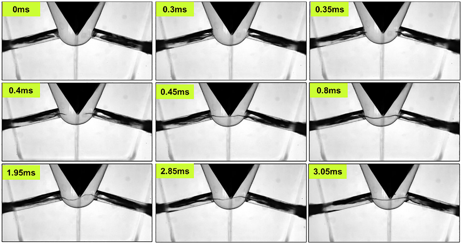
Figures 9 to 11 show the coexistence development of two cavitation patterns in the nozzle at 20°C, 40°C, and 60°C, respectively, which are dominated by geometry-induced cavitation on the upper wall and supplemented by cavitation on the middle position of the nozzle. In Figure 9, during a single injection, string cavitation in the middle of the nozzle is intermittently attracted by geometry-induced cavitation on the upper wall of the nozzle due to the respective low-pressure action in the center of the vortex field and the low-pressure area near the upper wall formed by the flow at the nozzle inlet (0.25 ms). At this point, the string cavitation in the middle of the hole develops toward the SAC volume against the flow direction on the side near the SAC volume, which is relatively short during the development (0.25–0.4 ms). However, when it develops into SAC volume, the development is blocked and repeated at the junction between the nozzle entrance and SAC volume (0.65–0.8 ms). In fact, after diesel fuel flows into the SAC volume from the upstream, part of the fuel first flows through the bottom of the SAC volume, and then changes the flow direction to flow into the hole under the restriction of the arc region at the bottom. The SAC volume is divided into left and right parts by the needle valve head, corresponding to two holes. Therefore, the rotational motion of upstream fuel in the middle area of the two holes in the SAC volume forms a regular vortex motion with the cumulative effect. At 1.5 mm needle lift, the vortex motion is less intense, which causes the pressure in the low-pressure region inside the vortex to oscillate around the saturated vapor pressure. When the local pressure in the vortex region is lower than the saturated vapor pressure, the string cavitation develops into the SAC volume, and in turn, returning into the hole. As the fuel continues to enter the SAC volume, the local pressure in the vortex region will eventually be reduced to below the saturated vapor pressure at a certain point, so that the string cavitation takes on a fully-developed state. As can be seen from the Figure 9, the string cavitation finally penetrates through the SAC volume and connects the two holes at 1.05 ms. However, as the fuel continues to flow in, it lasts 0.6 ms (1.05–2.65 ms), and finally the hole-to-hole string cavitation breaks at 2.65 ms and gradually disappears into the SAC volume (3.1 ms).

Cavitation flow pattern in nozzle at 20°C (h = 1.5 mm, Pinj = 0.90 MPa).
Cavitation flow pattern in nozzle at 40°C (h = 1.5 mm, Pinj = 0.90 MPa).

Cavitating flow pattern in nozzle at 60°C (h = 1.5 mm, Pinj = 0.90 MPa).
At 0.90 MPa injection pressure, the geometry-induced cavitation on the upper wall has developed to the point where the nozzle outlet is transformed into super-cavitation, and its axial development lasts with fuel temperature varying at the same injection pressure. The increase of fuel temperature is mainly promoted in the radial direction, making its strength slightly enhanced. On the other hand, the effect of string cavitation on the middle of the hole is only reflected in the downstream area (the mutual attraction increases between the two cavitation patterns).
In Figure 10, the string cavitation intensity at the hole central position also increases (0 ms), which means that its own vortex convergence effect enhances. Under the effect, the surrounding bubbles are more likely to converge into its interior. At the same time, the fuel viscosity is reduced with fuel temperature increasing, so that the free bubbles are more easily escaping from the fuel and entering the center of vortex flow field. Therefore, the combination of lower viscosity and higher saturated vapor pressure promotes the development of string cavitation. the movement speed of string cavitating toward SAC volume increases obviously with fuel temperature increasing, which only takes 0.150 ms (0.3∼0.45 ms) from the beginning to the complete penetration of SAC volume. The period develops smoothly without the repeated extension and shortening of the string cavitation observed at 20°C.
Further, the local pressure in SAC volume tends to develop easier to be lower than the saturated vapor pressure as fuel temperature increases, combined with the effect of low fuel viscosity, which promotes the inception and development of hole-to-hole string cavitation. The hole-to-hole string cavitation intensity is slightly stronger (0.8 ms) than that at 20°C, thus improving the stability of vortex structure. The duration of hole-to-hole string cavitation in SAC volume is also prolonged for 0.26 ms. It is worth mentioning that the stability of eddy current structure is not the stable position of eddy current region in the common sense, but the continuity of eddy current region still exists even if the position of eddy current region changes. And the continuity shows that the string cavitation does not destabilize and fracture with the oscillation of its local position. As shown in Figure 10, the string cavitation has oscillated into an S-shape in the SAC volume, but the cavitation still shows an inherent continuous shape (1.95 ms). Unquestionably, such violent oscillations last short—if the state sustains for a long time, the vortex structure will still be affected. Together, it is also found that even if fracture occurs in the hole-to-hole string cavitation, the local pressure around it will soon fall below the saturated vapor pressure again, and the string cavitation pattern restores to stability.
In Figure 11, the hole-to-hole string cavitation intensity further enhances at 60°C, and the vortex structure becomes more stable in SAC volume. The situation of the hole-to-hole string cavitation is similar to that at 20°C and 40°C, and also experiences the oscillation period (0.35–1.05 ms). In addition, there is no cavitating fracture occurring at low fuel temperature, although the hole-to-hole string cavitation intensity is observed (1.05–3.55 ms). The duration of hole-to-hole string cavitation in SAC is further increased to 4.9 ms (0–4.9 ms), again suggesting that high fuel temperature promotes the development and eventual stabilization of hole-to-hole string cavitation.
Periodic variation of string cavitation
Periodic characteristics of pressure fluctuations under three cavitation patterns
In Figure 12, a periodic transformation is observed between needle-originated string cavitation and geometry-induced cavitation at 60°C and 0.60 MPa. When the needle-originated string cavitation is transformed into geometry-induced cavitation, it is often accompanied by the hole-to-hole string cavitation appearing. Taking the first period as an example, the cavitating pattern is geometry-induced cavitation at the nozzle entrance at 0 ms. On the basis of geometry-induced cavitation, the hole-to-hole string cavitation begins to appear at 0.3 ms. However, its pattern presents unstable, appearing and disappearing intermittently. Combined with the amplitude of pressure fluctuation, the effect of hole-to-hole string cavitation is continually weak on the whole fluctuating cycle. After maintaining this state for a period, the cavitation pattern suddenly transforms to thick and strong needle-originated string cavitation appears at 0.95 ms. This type of string cavitation keeps good stability in the hole, sometimes accompanied by weak geometry-induced cavitation at the upper wall of the nozzle entrance. However, similar to the hole-to-hole string cavitation, the cavitating pattern also has little effect on the pressure fluctuations in the nozzle.

Periodic fluctuations of the pressure (h = 1.16 mm).
The same cavitating pattern converts differently with time in different cycles. Taking the string cavitation pattern as an example, in the first cycle, the fluctuation pressure first decreases and then increases; In the second cycle, the changes are relatively less drastic and remain stable as a whole. In the third cycle, the fluctuation pressure first increases and then decreases; In the fourth cycle, the pressure fluctuations continue to decrease. Geometry-induced cavitation pattern has no similar rules, in other words, the periodic appearance of string cavitation itself means the instability of cavitation pattern, even in the same pattern also shows a diversity of variation trends. Furthermore, the spray atomization in the near-hole area greatly depends on the flow in the nozzle and the initial flow conditions at the nozzle outlet. Different cavitating pattern has obvious effect on the near-field spray angle. Therefore, the periodic variation between the types of cavitation improves the uniform mixing extent of spray and air. The higher fuel temperature (60°C) makes the fuel easier to evaporate and further improves the distribution of the fuel in cylinder.
The effect of exfoliation cavitation on string cavitation at hole outlet
Under the small needle lift and low injection pressure, the cavitation in the hole regularly presents as the hole-to-hole string cavitation, and its morphology is demanding to maintain stability, which is based on the premise that the fuel keeps standard temperature. However, the primary string cavitation pattern performs variance at other fuel temperatures.
As shown in Figure 13, the cavitation phenomenon primarily in the SAC volume under the 60°C fuel temperature and 0.15 MPa injection pressure, there needs to be pointed out that, in addition to the case that cavitation pattern manifests as the needle-originated string cavitation when strong eddy current exists, the initial position of the other types of string cavitation usually lasts in the SAC volume or near the hole inlet (such as the hole-to-hole cavitation, as mentioned earlier). The reason is, the nozzle hole is the venting port of the fuel in the direction of the SAC volume, and the direction of its transition just happens near the hole inlet. The fuel transition forms a larger diversion curvature, causing string cavitation to be incepted in the SAC volume. In the swirling field, only the primary conditions are met by the local pressure regions due to strong transformation in the fuel direction. Therefore, string cavitation region during the period appears erratic and unstable. Due to the minimal centrifugal binding force, the post-primary peripheral region separates from the main region of string cavitation by upstream fuel (0 ms). However, the swirling flow region still exists in the hole, so it still moves to the hole outlet in the vortex region, and the part that falls off here is the upstream cavitating group mentioned above (0.1–0.3 ms). Although the low-pressure area recovers as it moves toward the hole outlet, the pressure it carries stands lower than the surrounding fuel pressure due to the swirling flow field. In this way, when moving to the hole outlet, the varied pressure distribution promotes the string cavitation incepting at the hole outlet (0 ms). However, due to the limitation of low injection pressure, string cavitation ceases to develop toward the hole inlet, but stays at the outlet (1.25 ms), which presents a periodic behavior (1.4–1.650 ms).

The string cavitation at the outlet caused by the falling cloud cavitation (h = 1.2 mm, Pinj = 0.15 MPa).
Conclusions
Based on the cavitation phenomenon and spray visualization in the diesel nozzle, the effects of constant injection pressure and fuel temperature on the inception and development of string cavitation and geometry-induced cavitation, especially the special string cavitation patterns in the nozzle are investigated. The main conclusions are as follows:
(1) Under medium high needle lifts, geometry-induced cavitation and hole-to-hole string cavitation simultaneously exist in the nozzle, and the inception of both cavitation patterns is compared and analyzed. Although the cavitation state of the hole-to-hole string cavitation is unstable at low injection pressure, it is relatively easier to incept. Under the same needle lift, increasing fuel temperature promotes the development of hole-to-hole string cavitation, whose structure persists more stable.
(2) The micro-size of the nozzle limits the fuel flow space in the nozzle. Therefore, when geometry-induced cavitation and hole-to-hole string cavitation occur simultaneously, the interaction inevitably occurs. After the hole-to-hole string cavitation incepts at the hole inlet, it is easy to be attracted by geometry-induced cavitation region during the constricting zone at the hole inlet. The vortex structure at the string cavitation inception is destroyed, and the vortex structure area reaches the cavitation incepting condition again with the fuel flow pulsation.
(3) Under high temperature conditions, low fuel viscosity weakens the hole-to-hole string cavitation retention, which is reflected in the cavitation structure under external interference. Therefore, the cloud cavitation that falls off the geometry-induced cavitating tail disturbs hole-to-hole string cavitation and leads it to fracture.
(4) In the case of weak cavitating intensity, there is a periodic change between the needle-originated string cavitation and geometry-induced cavitation. The instability of cavitation pattern promotes the fuel distribution in space, thus enhancing the uniform mixture of spray and air, and improving the spray atomization.
Footnotes
Handling Editor: Chenhui Liang
Declaration of conflicting interests
The author(s) declared no potential conflicts of interest with respect to the research, authorship, and/or publication of this article.
Funding
The author(s) disclosed receipt of the following financial support for the research, authorship, and/or publication of this article: This research was supported by Research Start-up Funds for High-level Talent in Wuxi Vocational College of Science and Technology (No.005000010).