
Abstract
Severe wear is a common damage mechanism in railway turnouts, which strongly affects the dynamic performance of railway vehicles and maintenance costs of tracks. This article explores the effects of profile wear on contact behaviors in the wheel–rail/switch contact and dynamic interaction, and nominal and measured worn turnout rail profiles are used as boundary conditions of wheel–rail contact. The calculation of the dynamic loads and the resultant contact stresses and internal stresses makes it possible to rationally design railway turnouts and correctly select the material to be applied for their components. For these reasons, the multi-body system SIMPACK and finite element software ANSYS are used to calculate the features of load and subsequently distributions of contact stresses and internal stresses in the regions of wheel–turnout components. The results show that profile wear disturbs the distribution of wheel–rail contact point pairs, changes the positions of wheel–rail contact points along the longitudinal direction, and affects the dynamic interaction of vehicle and turnout. For the measured profile in this article, profile wear aggravates vertical dynamic responses significantly but improves lateral dynamic responses. Profile wear disturbs the normal contact situations between the wheel and switch rail and worsens the stress state of the switch rail.
Keywords
Introduction
Turnouts (switches and crossings) are essential components of railway infrastructure, which provide flexibility to traffic operation. They are consisted of a switch panel, a crossing panel, and a closure panel, see Figure 1. 1 In the switch panel, multiple wheel–rail contacts are common and there is a disturbance to nominal wheel–rail contact conditions due to wheels’ transfer from stock rail to switch rail. 2 Dynamic interaction between the train and turnout is more complex than that on tangent or curved tracks and severe impact loads can occur, generating serious damage of the contact surfaces and transmission of noise and vibrations to the environment. In the case of a degraded turnout (e.g. severe wear of switch rail and stock rail), such wear causes a great change in rail profile and, therefore, strongly affects the running behavior of railway vehicles, such as motion stability, riding comfort, and derailment safety.3,4 The calculation of the dynamic load and the resultant contact stresses and internal stresses makes it possible to rationally design railway turnouts and correctly select the material to be applied for their components. In the literature, the effects of profile wear on wheel–rail contact behaviors and dynamic interaction of vehicle and turnout are investigated.

Components of a turnout. 1
Wheel–rail contact behaviors in the switch have been studied with a number of laboratory experiments and numerical procedures. For instance, Kassa and Nielsen5,6 used the commercial multi-body system (MBS) software, GENSYS, to model the dynamic interaction between the railway vehicle and turnout; in this model, the multiple wheel–rail contacts were considered and stochastic analysis methods were integrated to reach a robust design for wheel–rail contact conditions in the turnout. Wiest and Kassa assessed four models for wheel–rail rolling contact at a given cross section in the crossing panel of a selected turnout design, namely, Hertz and the non-Hertzian models implemented in the computer program CONTACT, elastic, and elastic-plastic finite element models. It is found that the contact pressure distributions calculated using Hertz and CONTACT correlate well with those results obtained from the finite element method as long as no plasticization of the material occurs. 7 Pletz et al. 8 presented a finite element model for the process of a wheel passing a crossing in which the rolling/sliding behavior between the wheel and crossing, impact loading, and equivalent plastic stress/strain were studied at the different train speeds and in different passing directions. Alfi and Bruni 9 proposed a mathematical model of train–turnout interaction in the mid-frequency range and presented comprehensive results of train–turnout interaction during the negotiation of the main and diverging lines, including the effect of wheel–rail profiles and presence of track misalignment. Sebes et al. 10 described the semi-Hertzian method to solve the wheel–rail contact problem, which enabled the derivation of more arbitrarily shaped contact patches than the elliptic ones supplied by the Hertzian theory, taking the changing rail profile into account via an interpolation process function of the distance. Aniołek and Herian used the Universal Mechanism and MSC MARC computer applications to determine the characteristics of load and subsequently distributions of contact stresses and deformations in the places of the wheel–crossing component contact. This model made it possible to rationally design railway turnouts and correctly select the material to be used for their components. However, only nominal rail profiles and one cross section of frog are considered in the simulation. 11 Ren made full use of the wheel–rail spatial geometry contact theory and Hertzian nonlinear elastic contact methods to study the wheel–rail two-point contact relationship. He also used these to simulate the characteristics of the wheel–rail forces’ distribution and transfer from one rail to another. 12 Wang 13 and Wang et al. 14 proposed a spatial coupling model for railway turnout systems to compare the differences in dynamic characteristics between the turnout with movable frog rail and the turnout with rigid frog on the basis of the characteristics of the idealized turnout structures. Zeng et al. 15 built the rail-turnout-tie-bridge spring-damping vibration model using finite element method, and they derived the spatial vibration equation sets of the system using the principle of invariant total potential energy in elastic system dynamics and the “set-in-right-position” rule for formulating matrixes to study the response of the vehicle and turnout. The above reviews showed that most of the current researches on the contact behaviors in wheel–rail/switch contact were based on contact models of nominal profiles, while the realistic profiles varied all the time due to wheel–rail wear. It is noticed that there is little study about the effects of profile wear on wheel–rail contact behaviors and the dynamic interaction of vehicle and turnout.
In this article, the effects of profile wear are accounted for in the simulation. The profiles of switch rail are obtained by sampling several cross sections at certain positions along the turnout. Nominal and measured worn switch rail profiles are used as boundary conditions of wheel–rail contact. First, the geometric parameters of wheel–rail contact are calculated to analyze the effects of profile wear on the distribution of wheel–rail contact points and the positions of wheel–rail contact points along the longitudinal direction. Then, an MBS model of the vehicle and a space-dependent model for the railway turnout are built in SIMPACK and both nominal and measured worn switch rail profiles are accounted for. The dynamic responses of the vehicle–turnout system are acquired and compared with each other. Finally, the finite element software ANSYS is implemented to calculate the distributions of contact stresses and internal stresses in the regions of wheel–turnout component by taking the dynamic response as inputs. The elastic-plastic material properties have been taken into consideration.
Measurement of switch rail profiles
The large contribution of reported track faults is associated with turnouts and this leads to higher maintenance costs than for other parts of the track. Furthermore, failure or disturbance of a turnout may lead to an indirect cost in the form of a traffic shutdown. One of the common damage mechanisms in railway turnouts is severe wear. Examples of damage are illustrated in Figure 2. In Figure 2, severe wear has occurred at the switch rail and the stock rail. The measurement was performed at a CN60-350-1:12 turnout on Meichi No. 1 Bridge of the Zhejiang–Jiangxi Railway Line in China. The measured switch rail profiles are used in the through route. The stock rail has severe vertical wear and the rail corner shows fine cracks and shelling defects; the shape of the rail head got into flat and the height reduces. The switch rail has serious side wear, the width of the rail head decreases, and the point almost becomes flaked. The rail wear makes the transition of loadings unreasonable, and a wheel flange may climb the switch rail resulting in a vehicle derailment.

Rail profiles’ wear.
The nominal geometry of the studied turnout is a standard design CN60-350-1:12 (curve radius 350 m, turnout angle 1:12). The variation of rail profiles along the turnout is accounted for by sampling the rail cross sections at several positions, as shown in Figure 3. Worn rail profiles are measured using the device MiniProf and the wear loss of measured rail profiles in the switch panel is shown in Figure 4, in which the scatter points, respectively, stand for the positions of the seven rail sections. The side wear is measured at gauge line and the vertical wear is measured at the center of the rail profile. It could be seen that both stock rail and switch rail had serious wear. The wear loss was not constant along the turnout’s longitudinal dimension. The side wear of the switch rail occurred before the distance of 5.0 m from the point of the switch rail and it got to maximum 3.51 mm at the distance of 1.15 m. The vertical wear of the switch rail occurred from the distance of 0.96 m. The vertical wear of the stock rail occurred along the turnout and decreased at the distance of 1.68 m.

Positions of measured rail profiles.

Wear loss of rails in the switch panel.
The nominal and worn rail profiles are compared in Figure 5 and rail profiles at seven positions are taken as example. For nominal profiles, the stock rail has the uniform cross sections, while the cross sections of the switch rail change gradually until it has the same width and height as the stock rail, so that the wheel load could transfer from stock rail to switch rail smoothly. But for worn profiles, the stock rail has non-uniform cross sections due to material loss. The switch rail profiles have large and complicated changes, and this will strongly affect the wheel–rail contact behaviors and dynamic interaction of vehicle and turnout.
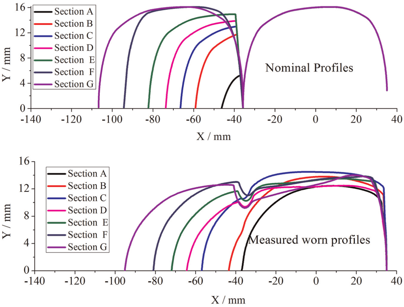
The comparison of nominal profiles and worn profiles.
Calculation of wheel–rail contact geometry
Calculation principle
The calculation of wheel–rail contact geometry is used to analyze the influence of the profile wear on the distribution of wheel–rail contact points and the positions of the wheel–rail contact points along the longitudinal direction. The calculation is based on the wheel–rail contact points’ trace principle. First, potential contact point pairs (or contact point traces) on both the wheel profiles of a single wheelset are to be obtained with the calculation of pure geometry form, and second, the minimum distances between contact points’ traces and turnout rail profiles are to be computed. When the minimum distances at both sides get the same value, the locations of contact points could be determined. 16
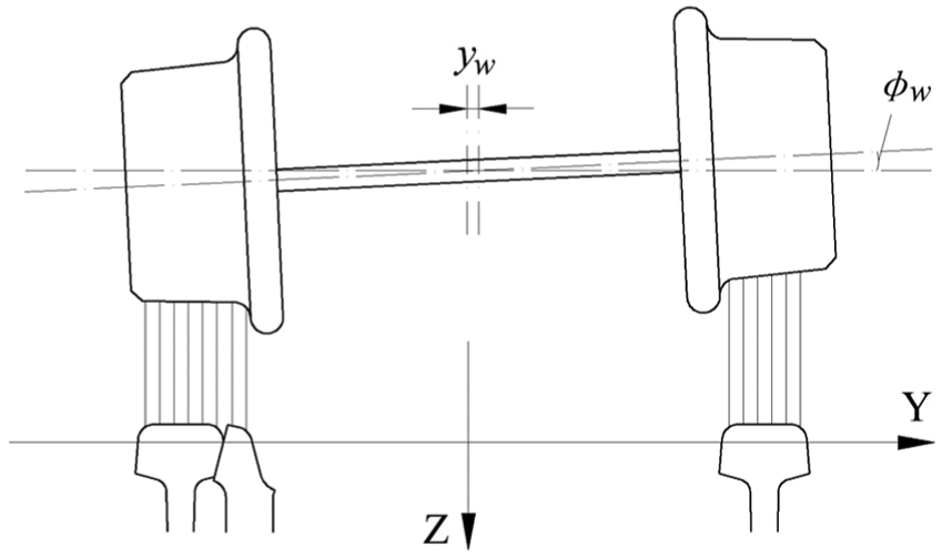
Figure 6 schematically depicts the wheel–rail contact points’ trace calculation. In the diagram, the X-axis represents center lines of the track, whose positive direction is the advancement direction of the vehicle. The Y-axis represents transverse direction of the track, which is perpendicular to the X-axis. The Z-axis is the vertical direction of track; its positive direction is downward; the O is the point of origin for global coordinate system; Cr and C are the wheel–rail contact point and the lowest point of real rolling circle, respectively; O1, A, and O2 are the center point of real rolling circle, point of intersection for contact normal and the center line of the wheelset, and the center point of the wheelset, respectively;

Schematic diagram of wheel–rail contact points’ trace.
The wheel–rail contact point Cr is located in the three space planes: the plane of rolling circle with the center O1, plane of

where lx, ly, and lz denote the direction cosine of coordinate system of the wheelset. The trace of wheel–rail contact points is the set of potential contact points on the different rolling circle, which can be determined through changing the lateral distance
Determination of wheel–rail contact points.
Calculation results
Based on wheel–rail contact points’ trace principle, the wheel–rail contact point pairs are obtained at different wheelset’s lateral displacements from −12 to 12 mm. Sections A, B, D, and E shown in Figure 5 are selected to compare the results, and the calculation results are shown in Figure 8.

Distribution of wheel–rail contact point pairs.
The profile wear has a great influence on distribution of wheel–rail contact point pairs. For nominal profiles, the distribution of wheel–rail contact point pairs on the rail profiles is more scattered and it is good for the rail even wear. The wheel will contact with the switch rail at large lateral offsets and with the switch rail getting higher and wider; the probability that the wheel contacts with the switch rail will increase, as the wheel only contacts with switch rail of nominal profile E. For measured worn profiles, the distribution of wheel–rail contact point pairs on the rail profiles is concentrated and it will lead to groove wear on rail profiles. The wheel begins to contact with the switch rail of worn profile D, and it only contacts with switch rail of worn profile E. It can be concluded that profile wear shortens the range of the wheel load transfer from stock rail to switch rail and concentrates the distribution of contact points.
The positions of wheel–rail contact points along the longitudinal direction without the lateral offset of the wheelset are calculated and shown in Figure 9. The maximum amplitude of the variation of wheel–rail contact points in the lateral direction is 36.01 mm for nominal profiles; it is 11.42 mm for the measured worn profiles and falls by 60% due to the concentration of contact point pairs. The maximum amplitude of the variation of wheel–rail contact points in the vertical direction is 1.54 mm for nominal profiles. But there are two peak values for measured worn profiles and the maximum amplitude is 2.06 mm, and these will increase the dynamic interaction between the vehicle and turnout.

The positions of wheel–rail contact points along the longitudinal direction without lateral offset of the wheelset: (a) lateral direction and (b) vertical direction.
Dynamic interaction of vehicle and turnout
Calculation model
The vehicle–turnout dynamic interaction is simulated in the validated commercial software SIMPACK. The calculation model includes two interactive parts: a three-dimensional multi-body model of the Chinese high-speed vehicle CRH2 (see Figure 10) and a space-dependent model of railway turnout with flexible track foundation (see Figure 11), which are connected by a local model of wheel–rail contact. The varied rail profiles are realized by sampling several cross sections of switch rail and point rail at certain positions along the turnout. Normal wheel–rail contact conditions are disturbed at various locations along the turnout. The largest disturbances occur when the wheels transfer from stock rail to switch rail in the switch panel and in the crossing when the wheels transfer from wing rail to point rail. Such deviations from the normal wheel–rail contact geometry may lead to high-impact loads.
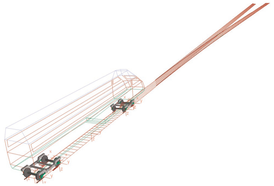
The multi-body model of vehicle.

Track foundation flexibility.
The calculation model of the vehicle includes modeling of carbody, suspension elements, bogies, and the wheelsets. In this article, a three-dimensional multi-body model of the vehicle is implemented. Carbody, bogie frames, and the wheelsets are modeled as rigid bodies; the parameter values of the vehicle model are listed in Table 1. The simulated turnout model is based on a standard design CN60-350-1:12 turnout (curve radius 350 m, turnout angle 1:12) and both nominal and measured worn profiles are accounted for. Furthermore, the specific features of a turnout, such as sudden changes in track curvature due to the absence of transition curves, cant deficiency, and the variations in rail cross section, are considered. The vehicle is switching into the turnout track in facing move in the simulation.
The parameter values of vehicle model.

The variation of rail profile makes the wheel–rail contact in the railway turnout more complex. Multipoint contact conditions are common because of the geometry of the rail profiles and the large lateral wheelset displacements that lead to flange contact on the outer rail. The contact geometry problem is solved in advance. The precalculated contact point functions are saved in tables and used in the integration analysis. The locations of the contact points and the corresponding contact angles determine the locations and the orientations of the contact forces, respectively. Hertz contact theory is applied for calculation of the normal contact force and the FASTSIM algorithm is used to solve the tangential contact problem.
The dynamic simulation could predict the motions of vehicle and wheelsets and wheel–rail contact forces. The dynamic responses, such as the locations of wheelsets and the normal forces, are used as inputs for the following finite element model to simulate distributions of contact stresses and internal stresses in the regions of wheel–turnout component.
Dynamic responses
The effects of profile wear on the dynamic interaction between vehicle and turnout are analyzed and the simulation is carried out at the speed of 120 km/h for the vehicle. The calculation results include the vertical and lateral wheel–rail contact force at the side of switch rail, the vertical vibration acceleration of carbody (the vibration acceleration is calculated at the center of mass of carbody), and the lateral displacement of wheelset, as shown in Figure 12.
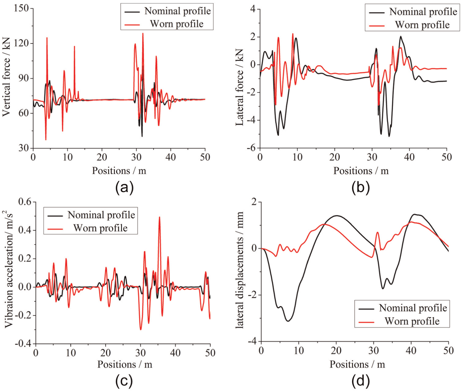
The comparison of dynamic interaction: (a) vertical contact force, (b) lateral contact force, (c) vertical acceleration of carbody, and (d) lateral displacement of wheelset.
It is concluded that profile wear has a great influence on dynamic interaction between the vehicle and turnout. For the worn profiles measured in this study, profile wear aggravates the vertical dynamic responses and improves the lateral dynamic responses. In the switch panel, the maximum vertical contact force is 88.1 kN for nominal profile and it is 124.88 kN for worn profile, increased by 41.75%. The maximum vertical vibration acceleration of the carbody is 0.09 m/s2 for nominal profile and it is 0.2 m/s2 for worn profile, increased by 122%. It could be explained by the variation of wheel–rail contact points for worn profile; it aggravates the wheel–rail dynamic interaction and increases the carbody’s vibration response due to the abrupt changes of wheel–rail contact points in the vertical direction.
However, the profile wear slows down the lateral dynamic interaction between the vehicle and turnout due to the decreasing degree of the variation of wheel–rail contact points in the lateral direction for worn profile. In the switch panel, the maximum lateral contact force is 5.08 kN for nominal profile and it is 2.89 kN for worn profile, decreased by 43.11%. The maximum lateral displacement of the wheelset is 3.13 mm for nominal profile and it is 1.02 mm for worn profile, decreased by 67.41%.
Determination of contact patch and distribution of contact stresses
Finite element model
The switch rail profiles have been designed to be varied along the switch panel and are combined together with the stock rail. The variation in rail profiles changes the boundary conditions of wheel–rail contact, which makes the contact conditions in turnout more complicated than the ordinary track. Finite element method is able to describe the contact behavior by considering material plastic property. 18 So it is applied to determine the contact patches and calculate the contact pressures.
In this article, ANSYS software is applied to build the finite element model of wheel–rail contact, and nominal and measured worn turnout rail profiles are used as boundary conditions of wheel–rail contact. The wheel and rail bodies are divided into a finite number of elements in the simulation, see Figure 13. The rails between two fastener systems are taken to build the model and the rail elements are supported by a distributed layer of springs with the stiffness of 50 kN/mm at the fastener position. The wheel elements are allowed to take place displacement vertically and laterally; the wheelset lateral displacements and dynamic normal contact forces simulated in SIMPACK are inputs for the same locations of the finite element model; finally, static analysis at given locations along the switch is calculated. Due to the obvious deformations occurring in the wheel–rail contact patch, the contact of two bodies is treated to be flexible. There is large stress concentration in the contact patch and it leads to great stress gradient at the boundary of contact region. The accuracy of calculation mainly depends on the sizes of the elements, but there is always a trade-off between accuracy and computational efficiency. To overcome this problem, the contact bodies are meshed finely in the potential contact region with a minimum element size of 1 mm on the surface. However, those far away from contact region are meshed badly with bigger element sizes, as shown in Figure 14.

The whole model of wheel–rail contact.

The local model of wheel–rail contact.
In the finite element model, bilinear kinetic intensify (BKIN) model is adopted to describe the elastic-plastic characteristic of wheel and rail material, which obeys Von Mises yield criterion and kinetic hardening rule. The Von Mises yield criterion is expressed by

where
When the equivalent stress

where

Equivalent stress–strain curve of wheel–rail material.
Calculation results
The vehicle–turnout dynamic responses such as the normal contact forces and lateral offsets of the wheelset are used as inputs for the finite element model. Also Sections A, B, D, and E are selected to compare the results, and the calculation results are shown in Figure 16.

Distribution of wheel–rail contact pressures (the above for nominal profile and the below for worn profile): (a) profile A, (b) profile B, (c) profile D, and (d) profile E.
It can be seen that the profile wear has a great influence on distribution of contact pressures and contact patches. The contact pressures for worn profiles are smaller than those for nominal profiles. The profile wear improves conformal contact between wheel and rail; the conformal contact can increase the contact patches and reduce the contact stresses. But there are three peak values of stresses existing on contact surfaces for worn profile A; it makes the contact patch and stresses larger at the same time due to abnormal wear. Also, the profile wear changes the state of stresses for switch rail. In the simulation, the wheel begins to contact with the switch rail at nominal profile D; the stock rail and switch rail bear wheel load together at nominal profile D and nominal profile E. But the wheel contacts with the switch rail at worn profile E and the two rails bear wheel load together. The calculation results do not agree with the results in section “Calculation results” (under section “Calculation of wheel-rail contact geometry”), because the wheel and rail are regarded as rigid bodies and contact region assumes to be a point in the calculation of wheel–rail contact geometry, while the finite element method can consider elastic-plastic material properties, and while contact regions are more accurate.
The finite element method is able to simulate the internal stresses of wheel and rail, the calculations of Von Mises stresses for selected profiles are shown in Figure 17, and the distributions of Von Mises stresses along the x3-direction (vertical direction) are shown in Figure 18.

Von Mises stresses of wheel–rail contact (the above for nominal profile and the below for worn profile): (a) profile A, (b) profile B, (c) profile D, and (d) profile E.

The distribution of Von Mises stresses along the x3-direction.
The maximum Von Mises stresses of wheel and rail are located at the region of 2.7–4.5 mm right under the rail surface, and plastic strains will occur in this region. The internal crack initiation begins when the cumulative plastic strains reach the limit value. The profile wear cannot always decrease the Von Mises stresses. For profile A, the profile wear increases the contact roughness which will lead to the increase in Von Mises stresses. For profile D, the profile wear makes the wheel contact with the stock rail only and increases the Von Mises stresses. For profile E, the profile wear worsens the conditions of wheel and rail contact; the wheel contacts with the edge of switch rail which makes the Von Mises stresses larger than nominal profile.
Conclusion
The effects of profile wear on the wheel–rail contact behaviors and dynamic interaction of vehicle and turnout are simulated in this article. Both nominal and measured worn profiles are taken as inputs for the simulation. The profile wear strongly affects the wheel–rail contact behaviors and the dynamic interaction of the vehicle and turnout. The outcome of this article could provide some theoretical guidance for the profiles optimization and grinding of switch rail and modify dynamic performance of the vehicle and thus increase ride quality. According to the simulation, it can be summarized that
For the measured worn profiles in this article, the profile wear shortens the range of wheel load transfer from stock rail to switch rail and concentrates the distribution of contact points. It decreases the amplitude of the positions’ variation of wheel–rail contact points in the lateral direction but increases in the vertical direction.
The profile wear has a great influence on dynamic interaction between the vehicle and turnout. Due to the abrupt changes in wheel–rail contact points in the vertical direction, the profile wear aggravates the wheel–rail dynamic interaction and increases the carbody’s vibration response; the maximum vertical contact force and vibration acceleration of the carbody for worn profile increase by an amplitude of 41.75% and 122%, respectively. Similarly, the improvement of the variation of wheel–rail contact points in the lateral direction slows down the lateral dynamic interaction between the vehicle and turnout; the maximum lateral contact force and the lateral displacement of the wheelset for worn profile decrease by amplitude of 43.11% and 67.41%, respectively.
The profile wear affects strongly the distribution of the wheel–rail contact stresses and the internal stresses. Usually, profile wears could improve conformal contact between the wheel and rail and decrease the contact stresses, but in wheel–rail/switch contact, the profile wear may increase the surface roughness of wheel–rail contact, which leads to the increase in contact stresses.
The rail wear in railway turnouts is a long-term and complicated process, which is remarkably affected by the dynamic interaction between the vehicle and turnout and affects the dynamic interaction in reverse. In the future work, the rail profile evolution at different positions along the longitudinal direction for different total tonnages will be simulated. At each simulation step of dynamic interaction between the vehicle and turnout, dynamic responses such as wheel–rail contact forces and local creepages are the inputs for the wheel–rail rolling contact model. The simulation of wheel–rail rolling contact can provide the contact patches’ information for the wear model to calculate the volume of removed material in contact patches, and the wear distribution along turnout’s longitudinal dimension and wear depth in the rail profile can be obtained by the simulation of accumulated wear. With the smoothing of wear depth, the rail profiles can be updated and then fed back to the simulation of dynamic interaction between the vehicle and turnout.
Footnotes
Academic Editor: Shan-Tung Tu
Declaration of Conflicting Interests
The author(s) declared no potential conflicts of interest with respect to the research, authorship, and/or publication of this article.
Funding
The author(s) disclosed receipt of the following financial support for the research, authorship, and/or publication of this article: This work was supported by the National Natural Science Foundation of China (51425804 and 51378439) and the Key Project of the China’s High-Speed Railway United Fund (U1334203 and U1234201).