
Abstract
The design methodology and validation of a compliant translational joint–based force/displacement integrated sensor is presented in this article. The stiffness analysis of the large displacement high precision compliant translational joint is developed, in which the screw theory–based symbolic formulation method for structures is employed. By combining the stiffness matrix of the single compliant beams and components in this joint, the entire stiffness matrix is derived. The stiffness matrix is validated by finite element analysis (FEA) method. Finally, the compliant translational joint was fabricated with a three-dimensional printer and equipped with a linear position sensor and microcontroller. The displacement of the translational joint is measured and then the force is calculated using the stiffness matrix. A calibration is conducted so that the sub-Newton precision of the sensor is achieved.
Introduction
In certain special applications such as redundantly actuated parallel manipulators as shown in Figure 1, the displacement/force integrated sensor is of great use for measuring both displacement and force simultaneously, and improving the safety of the mechanism in the presence of internal redundant actuating forces. A mechanical element or equipment with the ability to conduct displacement/force transmission is indispensable in this kind of application. Moreover, compared with the traditional mechanism, compliant mechanisms have significant characteristics including monolithic manufacturing, high precision, no need of lubrication, and no pollution.1–3 And the compliant mechanism can also overcome the high cost of the processing and assembly of traditional mechanism, the clearance of the kinematic pair and the friction, and so on. Therefore, compliant mechanisms have found wide applications in the micro manipulation, 4 medical instrumentation, 5 precise positioning, 6 micro-electromechanical systems (MEMS) devices,7,8 and so on. A compliant joint (also known as flexure) is one of the basic components of the compliant mechanisms, which utilizes the small deformation and self-recovery characteristics of compliant elements to eliminate the backlash and mechanical friction, thus obtains ultra-high displacement resolution, and compact mechanical structure, high stiffness, and quick response.
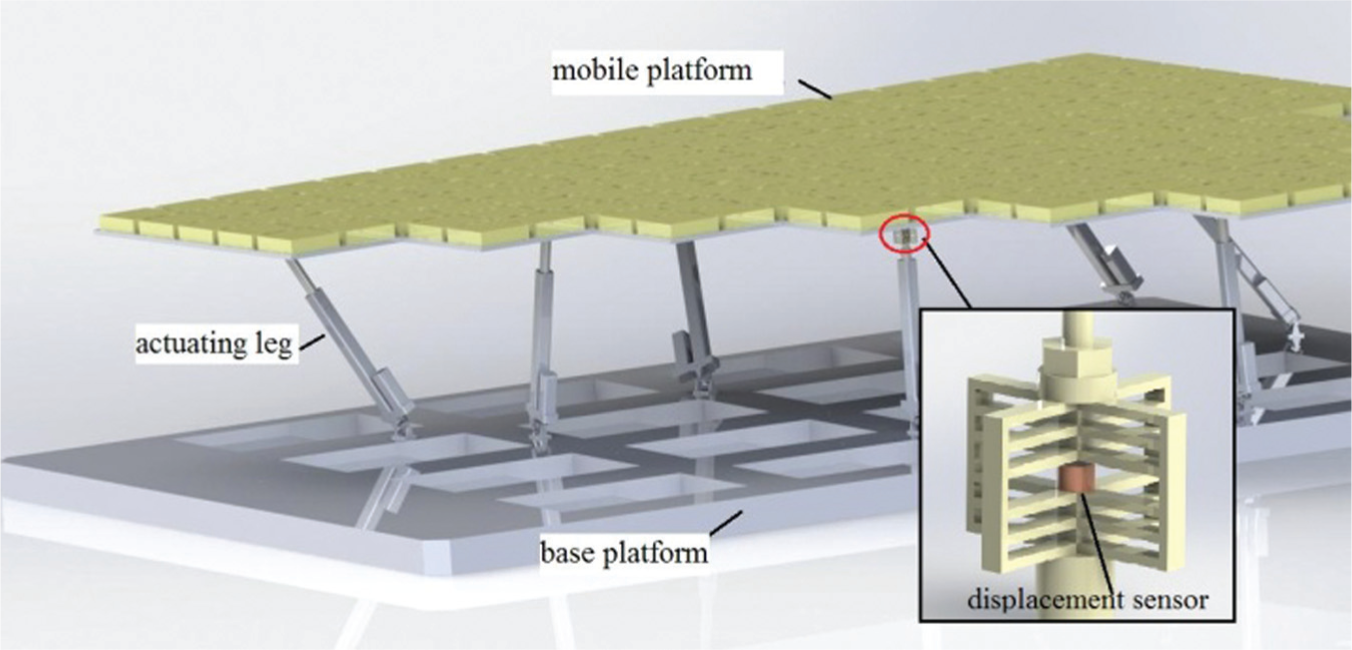
A displacement/force integrated sensor in a radar system.
As being subject to the constraints of the permissible stresses and strains in the material, the motion range of compliant joints is relatively small. When the yield stress of the material is reached, elastic deformation becomes plastic, after which the behavior of compliant joint is unstable and unpredictable. Therefore, the range of motion is determined by material property and geometry of the joint. Trease and Moon et al. 9 proposed the configuration of a large displacement complaint translation joint (CTJ), which has a lot of advantages illustrated in their research, such as the large stroke, the small axial drift, the weak effect of stress concentration, the strong shaft stiffness, and the compact structure.
Once the CTJ is used as a transmission element from force to displacement, the computation of stiffness (or compliance) of the compliant joint is critical in the design process. The fundamental task of the stiffness analysis is the mathematical description of the load and deformation relation of the compliant joint. This article adopts the analytical method of compliance of the compliant joint based on the screw theory,10–12 in which the stiffness matrices of multiple compliant components are combined, through the decomposition of the component of the complex compliant joint, and then the entire stiffness matrix of the compliant translation joint is formed. Finally, the effectiveness of the result is verified through the finite element analysis (FEA) simulation. Finally, a microcontroller-based measuring and displaying system is equipped on the CTJ to achieve the goal of force/displacement measurement.
The remaining of this article is organized as follows. The structure description of the large-stroke CTJ is given in section “Structure description of the large-stroke translational joint”; The detailed analysis of the stiffness matrix of the compliant joint is developed in section “Analysis of stiffness matrix of the CTJ”; The verification via the FEA method is carried out in section “Verification via the FEA”; The fabrication of and experiment on the compliant translational joint–based displacement/force sensor are elaborated in section “Fabrication and experiment”; As a summary, some meaningful conclusions are drawn in section “Conclusion.”
Structure description of the large-stroke translational joint
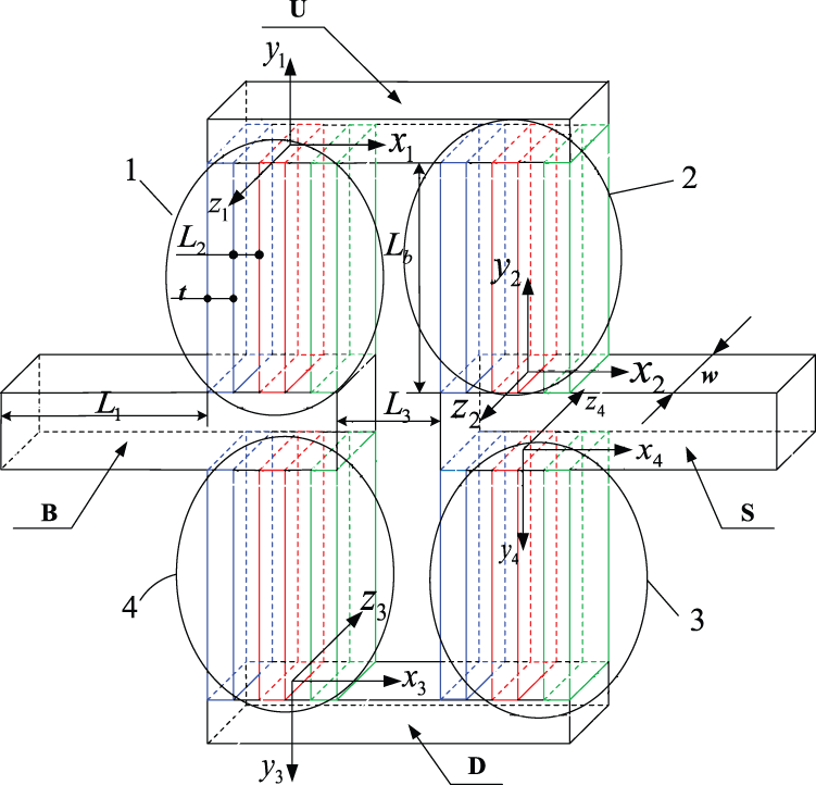
The compliant translation joint (CTJ) shown in Figure 2 is an entirety that is composed of two identical parts in quadrature as shown in Figure 3. The entire CTJ consists of 24 flexible beams in the middle and the rest six connecting rods regarded as rigid bodies. Components labeled with B and S are respectively connected to different parts, and the sliding motion between these two components is realized by the lateral deformation of the thin flexible beams.

Large-stroke CTJ.
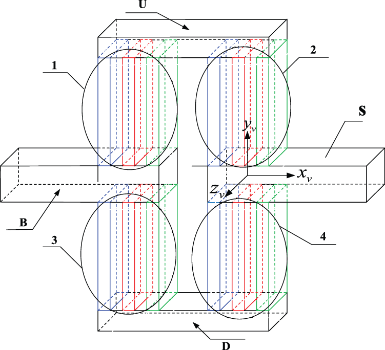
Components topology in the CTJ.
Two hypotheses on the CTJ component are made firstly to derive the stiffness: (a) six connecting rods are ideally rigid and (b) 24 flexible beams satisfy the linear elastic model and the small deformation conditions in the operation of CTJ. These two identical parts in quadrature of the CTJ work together so that they are of parallel relation concerning stiffness. The entire stiffness matrix of the CTJ can be formed by the stiffness matrices of these two identical parts represented in the same coordinate system. To start with, therefore, the entire stiffness matrix of the vertical part shown in Figure 3 needs to be derived.
The four substructures (or parts) in the circles in Figure 3 comprise totally 12 flexible beams, and they also have a parallel relationship among the other three flexible beams in each circle. Both ends of these parts are fixed to the two rigid bodies. Four substructures labeled by 1, 2, 3, 4 in Figure 3 are constituted by the rigid body at both ends of the three flexible parts parallel. The substructure numbers are referred to hereinafter. The substructures in Figure 3 are connected by four rigid parts labeled U, D, B, S, respectively. Parallel substructures 1 and 2 are connected in series by the rigid body U, while parallel substructures 3 and 4 are connected in series by the rigid body D. Then the above-mentioned two serial substructures are connected in parallel by the rigid bodies S and B. Here the rigid body B is considered as the fixed reference base, while the rigid body S is the actuating body to be studied. Eventually, the relationship between the force screw and the displacement screw generated at the origin of a coordinate system on the rigid body S will be derived (i.e. the stiffness matrix or compliance matrix).
Analysis of stiffness matrix of the CTJ
Stiffness matrix of the parallel substructures 1 and 2 in O 1 X 1 Y 1 Z 1
For the parallel substructure 1 shown in Figure 4, one end of its flexible beams is fixed to the rigid body B, while the frame O 1 X 1 Y 1 Z 1 is established with the origin at the center of the other end (fixed to the rigid body U). In this case, the stiffness matrix of the flexible beams in O 1 X 1 Y 1 Z 1 is also the stiffness matrix at the center of the free end of cantilever beam. By the knowledge of mechanics of materials, 13 one can obtain

where the left vector
Relationship of the CTJ compliant components.
The origins of local coordinate systems of the first and the third flexible parts in substructure 1 are located at the center of the end plane by which they are fixed to the rigid body U. Their orientations are identical to that of O
1
X
1
Y
1
Z
1. Therefore, the expression of either stiffness matrix of these two parts is the same as

where
The stiffness matrix

Since the stiffness matrix of the second flexible part is already described in the coordinate system of
Combinational stiffness matrix of serial structure 1 and 2 in
The compliance matrix of structure 1 is

The compliance matrix of the parallel structure 1 transformed into O 2 X 2 Y 2 Z 2 is

As the compliance matrix of the parallel substructure 2 is expressed in the coordinate systems of
Combinational stiffness matrix of serial substructures 1 and 2 in
Figure 4 shows the difference between the local coordinate system of
By the property of the upper and lower symmetry of the CTJ, the entire stiffness matrix obtained by the connection of substructures 3 and 4 in series in the coordinates of
Combinational stiffness matrix of the compliant structure
As shown in Figures 4 and 5, the origin of the coordinate of

Compliant beams in the horizontal plane.
The transformation from the coordinate of
where
where

The combinational stiffness matrix converted from

Entire stiffness matrix of the compliant translational joint
Figure 3 is a schematic diagram of the vertical part of the compliant translational joint, which has derived the entire stiffness matrix in the coordinate of
The transformation from the coordinates of

where

The subscript htv indicates horizontal to vertical. Therefore, once

where KCTJ
denotes the entire stiffness matrix of the CTJ represented in coordinate of
Verification via the FEA
In order to verify the effectiveness of the stiffness matrix of the CTJ under the assumption of the small deformation and the linear elastic material, the static analysis is made using finite element method with SolidWorks Simulation module. An comparison between the results from the analytical model and the FEA model is implemented. The following parameters and their values are adopted to build the compliant translational joint model in the FEA simulation (Table 1).
Values of the design parameters of the CTJ.

In the FEA simulation, the meshing grade was set as Finest as a result 2880 Quadratic hexahedron (Solid186) elements were generated. And the material is polylactic acid (PLA), whose elastic modulus is
In order to validate the aforementioned analytical stiffness result, L 1 (illustrated in Figure 3) is decreased purposely here. The smaller size will yield the smaller deformation of the both end rods and make analytical model and FEA model more consistent to each other. It is also noted that this extra operation is particularly for model validation in this research, and it is thus no need to put in more consideration in practice for the following two reasons. Firstly, the assumption that some of the parts are rigid in this article has a small effect on the deformation of the flexible prismatic in practice; Secondly, the theoretical error caused by the small deformation and elastic material hypothesis and the error introduced by the rigid hypothesis in the formula will be compensated for by the immediately following sensor calibration altogether.
The deformation ratio for displaying is set to 50 and displacement plot along the axial direction is shown in Figure 6. From this figure, one can observe that the maximum displacement (displacement at the end plane where the axial loading pressure is applied) is 8.7734 mm.

Axial displacement under the 40 N load.
Figure 7 shows that the largest von Mises stress in the compliant translational joint under the axial pressure of 40 N is

Von Mises stress under the 40 N load.
Additionally, through the entire stiffness matrix of the CTJ obtained above, one can obtain

In fact, this result agrees with our intuition and can be explained as follows. Under the loading force F perpendicular to a beam axis at the free end, the deflection of a cantilever beam is
Fabrication and experiment
To fabricate the prototype of this research, a MakerBot Replicator 2 model 3D printer with PLA material was employed. This 3D printer has a printing layer resolution of 0.1 mm. The PLA material has a density of 1250 kg/m3 and Young’s modulus of about 400 MPa from the data sheet. The measurement of displacement is conducted with a KSP-5 mm round self-recovery linear displacement sensor, which has a displacement range of 3 mm and repeatability of 0.01 mm. A BST-V51 microcontroller kit is used to read the displacement value, calculate the force, and display the result. The microcontroller is STC89C52 with main frequency of 11.0592 MHz. The on-board 8-bit A/D converter is utilized to implement the conversion of analog signal of voltage to digital signal.
After the fabrication and setting up of the force/displacement integrated senor. The calibration of the sensor was conducted as follows. A series of loads were applied on the vertically mounted sensor, the displacement of the sensor was recorded from the readings of the liquid crystal display. The force and displacement data pairs were recorded, so that the stiffness curve from linear data fitting was shown in Figure 8.

Axial stiffness curve fitting of CTJ.
It is also noted that the total stiffness matrix of the integrated displacement/force sensor includes the stiffness of linear displacement sensor
Eventually, the equivalent value of stiffness
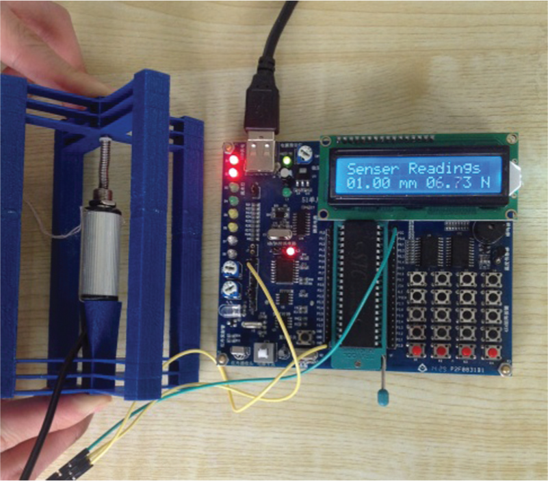
Measurement of the integrated sensor.
Conclusion
This article elaborates the development and verification of a large-stroke compliant translational joint–based force/displacement integrated sensor. The analytical stiffness matrix of the compliant translational joint is derived with screw theory. Then the sensor is implemented with a microcontroller and achieved the design specifications. Some meaningful conclusions can be drawn as follows:
Based on the assumption of small deformation for the compliant components, the stiffness matrix of the compliant joint can be analytically formulated using screw theory.
From the result obtained in FEA method, the derived stiffness matrix is of high accuracy and can be effectively applied to the stiffness analysis and synthesis of this kind of compliant joints.
In terms of inaccuracy of the material property of the prototype and other electronic equipments, the calibration of the integrated sensor on the stiffness should be conducted after fabrication. The performance out of the linear range of the force/displacement sensor can also be calibrated by experiment and accomplish the desired precision.
As a technical alternative solution, it is possible to use force sensor instead for the force/displacement measuring of the proposed integrated sensor. That is the future work by the authors, in which the precision, range, and response rapidity between these two types of technical solutions will be compared.
Footnotes
Academic Editor: Pedro AR Rosa
Declaration of conflicting interests
The author(s) declared no potential conflicts of interest with respect to the research, authorship, and/or publication of this article.
Funding
The author(s) disclosed receipt of the following financial support for the research, authorship, and/or publication of this article: This work was supported by National Natural Science Foundation of China under Grant Nos 51405362 and 51490660, and “111 project” under Grants No. B14042. The authors would also like to appreciate the Editor, Associate Editors, and the reviewers for their valuable comments and suggestions.