
Abstract
To work towards an advanced model of the bicycle-rider-environment system, an open-loop bicycle-rider model was developed in the commercial multibody dynamics software ADAMS. The main contribution of this article to bicycle dynamics is the analysis of tyre and rider properties that influence bicycle stability. A system identification method is used to extract linear stability properties from time domain analysis. The weave and capsize eigenmodes of the bicycle-rider system are analysed. The effect of tyre properties is studied using the tyre’s forces and torques that have been measured in several operating conditions. The main result is that extending simplified models with a realistic tyre model leads to a notable decrease in the weave stability and a stabilization of the capsize mode. This effect is mainly caused by the twisting torque. Different tyres and tyre inflation pressures have little effect on the bicycle’s stability, in the case of riding straight at a constant forward speed. On the other hand, the tyre load does have a large effect on bicycle stability. The sensitivity study of rider properties shows that body stiffness and damping have a small effect on the weave and capsize mode, whereas arm stiffness destabilizes the capsize mode and arm damping destabilizes the weave mode.
Introduction
Bicycling is a healthy, 1 effective and popular means of transportation. Furthermore, it is frequently used for social and recreational purposes. Even if the development of the bicycle was based on a trial-and-error process, dynamics of bicycles has drawn the interest of scientists and engineers for many years. In 1899, Carvallo and Whipple independently showed with the use of rigid-body dynamic models that some bicycles could balance themselves when riding at a certain speed.2,3 This linear model contained four rigid bodies, 3 degrees of freedom (DOFs) and a simplified tyre–road contact model: rigid-knife edge, pure-rolling and no-slip contact. The rider is modelled as a rigid body, rigidly attached to the rear frame.
In recent years, computer simulation proved to be a useful tool for studying bicycle dynamics and stability.4–6 Major contributions were made by Meijaard et al. 4 and Schwab et al., 7 who published and benchmarked the linearized equations of the Carvallo–Whipple bicycle model (CWBM). Their studies recently led to important insights into stability of a rider-less bicycle, which have been confirmed experimentally. 8
The CWBM is able to represent the capsize and weave modes, which play the main role in uncontrolled bicycle stability at low speed. Improvement of simulation requires extensions of the model such as the non-linearity of the bicycle dynamics, the passive rider dynamics and the interaction with the environment (i.e. tyre–road contact), which increase the complexity of the system considerably. Some efforts to extend the CWBM with realistic tyre–road contact models and rider models have been made. Sharp 6 numerically demonstrated that a more realistic tyre model strongly influences the weave and wobble modes of the bicycle. Similarly, Dressel and Rahman 9 showed the importance of upgrading existing bicycle models with the dynamic properties of tyres. Adding the rider’s dynamics changes the properties of the system significantly, and modelling of tyre properties could become even more important. 6 Recently, Plöchl et al. 10 gave details of a linear tyre model that includes self-aligning and twisting torques. The results showed a significant effect of tyre and rider properties on the stability of the wobble mode. Schwab et al. 11 incorporated passive properties of the rider into an open-loop bicycle model, without increasing the DOFs. They studied different rider postures, and it was shown that an upright passive rider could destroy the stability of the system by an unstable capsize mode. Recently, Doria and Tognazzo 12 experimentally determined the passive properties of the rider’s body and integrated the derived models in the benchmark model. Klinger et al. 13 combined a realistic tyre model with a passive rider model and studied the effect of different postures of the rider on the wobble mode, in the case of a racing bicycle.
Even if some recent bicycle models were developed by means of multibody dynamics software that is able to generate and solve non-linear dynamics equations, 11 in most researches, equations were linearized and a linear stability analysis was carried out. Also, in the field of motorcycle dynamics,14–16 it is a common practice to develop, by means of multibody dynamics software, models that take into account non-linear kinematics and tyre properties; the full non-linear model is used for performing time domain handling simulations only, while a linearized model is used for stability analysis.
This article is part of a research that aims to improve bicycle safety, with special emphasis on safety of elderly cyclists. To work towards an advanced model of the bicycle-rider-environment system, it was chosen to develop a non-linear model by means of a commercial multibody dynamics software. Operating in this way, it is possible to model a complex three-dimensional (3D) system and eventually simulate complex situations, for example, the behaviour of elderly cyclists in critical situations. In the next section, the multibody open-loop bicycle-rider model will be described; this model was developed in the software system MSC ADAMS and included bicycle dynamics, a passive rider model and a tyre–road contact model. For this last component, a specific version of the ‘Magic Formula’ tyre model 17 was used.
Stability is the main issue of single-track vehicle dynamics and it is related to safety, because on one hand uncontrolled unstable behaviour may lead to dangerous conditions, and on the other hand a skilled rider can obtain nice and quick manoeuvres by controlling an unstable system. This article focuses on stability analysis and the non-linear model is used for extracting linear properties in the case of riding at a constant forward speed. It appeared that for this specific modelling problem, the linearization within the commercial software package yielded rather muddled results; therefore, a system identification method was used to study the stability of two eigenmodes: weave and capsize. The weave mode is a combination of steer rotation and roll rotation of the whole bicycle, and the capsize mode is dominated by roll rotation. 7
The main contribution of this article to bicycle safety is the analysis of the parameters that influence stability, which can be grouped into tyre and rider properties. The effect of tyre properties is studied using the tyre’s forces and torques that have been measured in several operating conditions. 18 Regarding the rider’s properties, the effect of stiffness and damping properties of the limbs is dealt with. The body is represented with a lumped element approach using inertial values found in the literature 19 and recently measured stiffness and damping properties.14,20
Methods
The bicycle-rider model
The bicycle-rider model is in its entirety depicted in Figure 1. The bicycle’s dynamics is represented by four rigid bodies (the rear frame, the front assembly, the rear wheel and the front wheel). A revolute joint at the steering axis connects the front assembly to the rear frame. Both wheels are interconnected to the frame by revolute joints.

The open-loop bicycle-rider model developed in ADAMS. m1: rear frame; m2: front assembly including lower arm mass; m3: rear wheel; m4: front wheel; m5: pelvis; m6: upper body (including trunk, head and upper arm mass); m7: left leg; m8: right leg; K a: linear spring–damper representing the arms; Kw : rotational spring–damper around the longitudinal axis of the upper body at the waist; Kr : rotational spring–damper around the sagittal axis of the upper body at the waist; Kp : rotational spring–damper around the frontal axis of the upper body at the waist; Kl : rotational spring–damper around the line connecting the hips and the ankles.
The rider’s dynamics is also represented by four rigid bodies: the pelvis; the upper body containing the head, trunk and mass of the upper arms; and both legs. The pelvis is rigidly attached to the rear frame and the upper body connects to the pelvis with a spherical joint, at the L4–L5 vertebral joint position. The arms are modelled as linear spring–dampers between the handlebars and the shoulders, similar to Cossalter et al. 14 The linear spring–dampers generate a torsion stiffness and damping around the steering axis (coefficients Ka and Ba , respectively). The mass and inertia of the lower arms are added to the front assembly. In this way, all rotational DOFs of the upper body are maintained and the passive dynamics of the rider’s arms on the steering is taken into account. Passive springs and dampers are added to the rider’s joints. The values are adopted from Doria and Tognazzo 12 and are given in Table 3 of Appendix 1. Each leg is modelled as one rigid part and has 1 DOF: rotation around the line connecting the hip and the ankle. This allows for lateral knee movements, a movement which becomes interesting when rider control at low speed is considered. 21
Hence, the rider model contains 5 DOFs. The bicycle model has 9 DOFs, due to the modelling of the tyres as force and torque generators instead of constraints as being used in the CWBM. These are the positions (in all three directions) and orientations of the rear frame (roll, pitch and yaw), the spin angles of the wheels and the steering angle. Both the bicycle and rider model are fully parameterized, to enable modelling of any bicycle and any rider. Furthermore, it allows for parameter and optimization studies for improvement of the bicycle design (and possibly control) in order to increase safety. The bicycle used in this study is a regular bicycle with low entry (Twade T3001; Flexaim, Hengelo, The Netherlands). The geometry and mass properties of the bicycle are physically measured using the methods described in Moore et al. 22 The geometry and mass properties of the rider are estimated from the total weight and height of the person, using linear scaling and regression equations.19,23 The rider model used in this study is based on a male with a height of 1.80 m and a mass of 80 kg. See Appendix 1 and Figure 11 for the parameter values, as used in the model.
The tyre–road contact model estimates the forces acting between the road and the tyre. The actual load distribution in the contact area between the road and the tyre is recalculated into a set of forces and torques in one contact point. The inputs and outputs of the tyre model are given in Figure 2. In the radial direction, the tyre is considered to behave like a linear spring–damper, with one point of contact with the ground, point C in Figure 3. Tyre longitudinal and lateral forces and tyre torques are calculated by means of the Pac MC (Pacejka motorcycle) model of the package ‘ADAMS/tyre’, which is based on the so-called Magic Formula of Pacejka.17,24 In the next section, a more detailed description of the derivation of the tyre model properties is given.
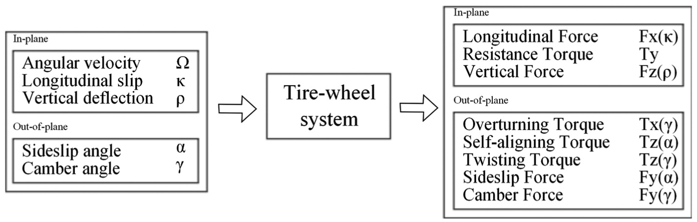
Definition of the inputs and outputs of the tyre–wheel system.

Coordinate systems, forces and torques exerted by the road on the tyre at contact point C, which is defined as the intersection of the road plane, the wheel centre plane and the plane through the wheel spin axis. (a) Coordinate system xwywzw is defined in ADAMS (ISO coordinate system: xw axis points towards the forward motion direction, zw axis points upwards and yw axis completes the tern). (b) Coordinate system xyz is defined in agreement with SAE (x-axis points towards the forward motion direction, z-axis points downwards and y-axis completes the tern). The forces and torques are measured in the xyz coordinate system (positive values are shown here) and given in ADAMS in the xwywzw coordinate system. (c) The contact point migrates to point S due to a camber angle; this effect is represented by the overturning torque.
Tyre model properties
The tyre model properties are based on the data measured by Doria et al. 18 They measured the tyre properties of four different bicycle tyres and studied the effect of working conditions, like the inflation pressure and load, on the mechanical properties of tyres. The characteristics of these tyres are given in Table 1.
Characteristics of the tested tyres in Doria et al. 18

All tyres originate from different manufacturers; note that tyre 3 has a smaller width and tyre 4 is a winter tyre, especially developed for snowy/icy roads.
For each given tyre, load and pressure, the Magic Formula coefficients are determined and used as the input to the model. The nominal load on the tyre, during the measurements, was set to 400 and 600 N. The tyre inflation pressure was varied between 2 and 5 bar.
The input for the model in ADAMS is a road property file and a tyre property file. The road property file contains the friction coefficient parameter (µr = 1.0) and dimensions of the road. The dimensions of the tyre, vertical stiffness (Kz ) and damping (Bz ) values and the Magic Formula coefficients are given in the tyre property file. Both the road and the tyre property file are included as Supplementary Material, to make it possible for other ADAMS users to use the developed bicycle tyre model.
It is worth highlighting that the non-linear description of the tyre’s behaviour, which is requested by ADAMS, could be useful for future handling simulations. For stability analysis, which is the focus of this article, a linear tyre model would be enough.
The vertical stiffness Kz of the tyre is based on a mathematical model that is used for calculating the vertical deflection of the tyre for different tyre inflation pressures and nominal loads. It is assumed that the contact patch has an ellipsoidal shape and a parabolic pressure distribution, 25 and that the tyre radius outside the contact patch maintains the unloaded value. The vertical deflection of the tyre ρ can be calculated using half the length of the measured contact patch area l and the unloaded radius of the wheel rf using the Pythagorean theorem. Subsequently, the vertical stiffness Kz can be calculated using the deflection and the known load on the wheel. The numerical value of the vertical damping Bz of the tyre is chosen sufficiently large to achieve supercritical responses and is given in Table 3 of Appendix 1.
For the calculation of the out-of-plane forces and torques acting by the road on the tyre as a function of the sideslip angle (α) or camber angle (γ), a specific version of the aforementioned Magic Formula is used, whereby the coefficient E (the curvature factor) was set to 0, see equation (1). Good fitting results were found using this simplified version of the Magic Formula 18

where y is the output variable Fx, Fy or Tz and x the input variable α, κ or γ. The B-coefficient is the stiffness factor, the C-coefficient the shape factor (>0), the D-coefficient the peak value and the E-coefficient the curvature factor.
In the linear range, equation (1) becomes

where
The lateral force Fy
(α,γ) at the contact point consists of two parts, called the sideslip force and the camber force, which are functions of the sideslip angle α and camber angle γ, respectively. The definitions of sideslip and camber angles are given in Figure 3. The self-aligning torque
The in-plane forces and torques were not measured except for the rolling resistance torque Ty . This torque was measured with the tester machine of Padova University 18 on a rotating wheel, while γ and α were set to 0. The mean and standard deviations of the measured rolling resistance torques as well as the fitting equation can be found in Appendix 1 (Table 4).
The forces generated under longitudinal slip κ are not measured by the above-mentioned tester machine. Therefore, assumptions for the longitudinal force Fx (κ) are made, which are based on motorcycle data (see Appendix 1). Since the lateral stiffness (Ka ) of bicycle tyres (about 4000 N/rad 18 ) is close to the lower limit of the lateral stiffness of motorcycle tyres, 26 the value of longitudinal stiffness Kκ of bicycle tyres is likewise chosen as the minimum value of the longitudinal stiffness of motorcycle tyres (4800 N) 26 with the same vertical load.
Since bicycle wheels are relatively thin and camber angles remain small, in the model the forces are applied at one contact point. This point (C) lies at the intersection of the wheel plane, the road tangent plane and the plane through the wheel axis (Figure 3(c)). However, in reality, due to a camber angle and the tyre cross section with radius rc , the contact point migrates and forces and torques are measured at a different point, point S in Figure 3(c). 18 For this reason an overturning torque has to be added. 6
The results of the tyre measurements presented in Doria et al. 18 show that the tyre properties are load-dependent, which is also observed for motorcycle and car tyres. 24 The scaling methods presented in Pacejka 24 are used to scale the tyre properties to the nominal load. The scaling coefficients are given in Appendix 1.
In the following sections, the discussion of the effect of tyre properties is based on the sign conventions used for measured data (according to Society of Automotive Engineers (SAE)).
Analysis of stability
As mentioned in the ‘Introduction’ section, the multibody dynamics software was not used for the linearization of the equations of motion. Alternatively, time domain numerical data were analysed by means of a system identification method. A lateral disturbance is given to monitor the response of the system. The disturbance is defined as a lateral force of 0.1 N lasting for 0.1 s applied at the position of the centre of mass of the bicycle rear frame.
The system identification toolbox of MATLAB is used to estimate a state-space model of the bicycle-rider system from time domain data generated by the ADAMS model for each defined forward speed. The input is the lateral disturbance signal, and the outputs are the steering and roll angle. The time domain results are fitted with a state-space model with four poles, corresponding to the four state variables (roll angle, roll rate, steering angle and steering rate). The weave and capsize modes are analysed. The lowest speed at which weave oscillations of the bicycle are damped (the real part of the eigenvalue is negative) is called the weave speed vw (this is the lowest speed at which the weave mode of bicycle model is stable). Below this speed, the oscillations increase and the bicycle will fall over. Capsize speed vc is the highest speed at which capsize is stable. Hence, the system is stable between the weave and capsize speed.
High-speed stability and the wobble mode are not analysed, since this research focuses on normal operations of bicycles ridden by common or elderly people.
Simulations
The ADAMS model and the system identification method are validated with the CWBM model, by implementing the benchmark parameter values. Next, the Magic Formula tyre model is implemented and comparisons are made.
Furthermore, the effect of the following extensions of the multibody model is tested: Magic Formula tyre model, rider joint properties, arm mass at the front assembly, arm damping and stiffness.
The simulations are carried out with tyre properties of different manufactured tyres and variations in tyre pressure and load. Subsequently, the effect of single tyre parameters is investigated, by changing one tyre parameter at a time (50% and 200%) while keeping the other parameters at the nominal value.
Finally, the effect of torsional arm stiffness and damping values is investigated, both with and without the Magic Formula tyre model.
Simulation results
Comparison tests
As indicated in the previous paragraph, the first step is taken by setting the parameters of the ADAMS model such that it resembles quite accurately the CWBM model with the benchmark parameters. 4 Hence, the rider is modelled as a rigid body stiffly attached to the rear frame and the rigid-knife edge, pure-rolling and no-slip contact are simulated by setting the radial and sideslip stiffness to very high values and the longitudinal force, camber force, twisting torque, self-aligning torque, rolling resistance torque and overturning torque to 0.
Figure 4(a) and (b) show that the non-linear simulation of the ADAMS bicycle model and the system identification method are valid between speeds of 4 and 10 m/s. Identification at lower speeds was poor, due to the instability of the bicycle model at these speeds.

Comparison between eigenvalues of the benchmark model found in Meijaard et al. 4 and the ones calculated by means of ADAMS and the identification method in the stiff tyre case and with the ‘Magic Formula’ tyre model: (a) real parts (black: weave mode, red: capsize mode) and (b) imaginary parts.
Subsequently, the Magic Formula tyre model is implemented in the CWBM model and comparisons are made with the stiff tyre case. The tyre model is based on the measurement data of tyre 2, with an inflation pressure of 4 bar and a nominal load of 400 N. The detailed tyre model with side slip force, camber force and torques leads to an increased weave speed vw = 7.4 m/s and a stable capsize mode in the presented speed range.
Effect of the extensions of the multibody model
In this section, the full ADAMS multibody open-loop bicycle-rider model is considered with the properties as listed in Appendix 1 (Table 3), which refers to the Twade bicycle and an 80-kg rider. The effect of several extensions of the model is studied. Table 2 lists the simulations that are carried out; the tested model extensions are displayed in bold.
Performed simulations, with the tested model extensions displayed in bold.

The mass and inertia of the arms are lumped in the rigid rider body.
Figure 5 deals with the effect of the model extensions on the weave mode and shows both the real (a) and imaginary (b) parts of the eigenvalues against forward speed.

Eigenvalues of several model extensions: (a) real parts (black: weave mode, red: capsize mode) and (b) imaginary parts.
The new bicycle-rider model with stiff tyre (no slip), rigid rider and arms off the handlebar (case 1) has a weave speed of 4.9 m/s, a bit higher than the one of the benchmark models. Capsize speed of the new model (6.8 m/s) is higher than the one of the benchmark models as well.
When the model is extended, the following results appear:
Passive rider joint properties (case 2) have a very small effect on the weave mode and show no significant effect on the capsize mode.
Arm mass (case 3) has a small effect on the weave mode; it increases weave frequency and weave speed. Furthermore, it results in a small decrease in vc .
Arm damping (case 4) causes a small increase in vw and a decrease in the weave frequency. No significant effect on the capsize mode was found for speeds above 6 m/s.
Low-speed stability is not possible with arms that have realistic stiffness (values are adopted from Cossalter et al., 14 case 5), owing to the presence of an unstable capsize mode. However, arm stiffness stabilizes the weave mode.
The Magic Formula tyre model (case 6) destabilizes the weave mode (weave speed increases to 9.3 m/s), but stabilizes the capsize mode. It is worth highlighting that in Klinger et al., 13 which considers a linear model of tyre forces and torques, weave speed is about 9.5 m/s and capsize mode is always stable.
When the full model is used (which includes the new tyre model, passive rider and arms), the capsize mode is always stable and weave speed increases a bit more with respect to case 6. This result means that the stabilizing effect of the tyre forces and torques on the capsize motion is larger than the destabilizing effect of arm stiffness.
Model sensitivity to tyre properties
The simulations carried out with different manufactured tyres and with the same tyre inflated at different pressures result in a small change in the weave speed and weave frequency. Tyre 3 (which is thinner than the others) shows a small increase in the weave speed (0.2 m/s), and tyre 4, the winter tyre, is a bit more stable over the entire speed range.
However, the vertical load on the tyre applied during the measurements of tyre properties influences the mechanical tyre properties and therefore also the stability of the bicycle. The simulation of the open-loop bicycle-rider model with the tyre model based on the measurements with a nominal load of 400 N resulted in a weave speed of 9.7 m/s. The simulation with the tyre model based on the measurements with a higher load (600 N) gave a weave speed of vw = 8.3 m/s (see Figure 6).

Eigenvalues for the open-loop bicycle-rider model when tyre parameters are based on measurements with a vertical load of 400 and 600 N, for two different tyres: (a) real parts (black: weave mode, red: capsize mode) and (b) imaginary parts.
The next step is an analysis of the sensitivity of the weave speed to the single tyre properties; Figure 7 shows the results. The variations of 50% and 200% of the nominal value of one property at a time are considered, keeping the other parameters constant. On one hand, cornering stiffness Kα has a small effect on the weave speed: doubling of the value decreases the weave speed by less than 1%. On the other hand, camber stiffness Kγ has a remarkable effect on the weave speed; if Kγ doubles, weave speed increases by 9%.

Sensitivity of weave speed to tyre parameters; it is expressed in percentage variation of the weave speed with respect to the nominal values.
Regarding the tyre torques, the twisting torque shows the largest effect on the weave stability. Parameter DTT is the coefficient that determines the linear dependency of the twisting torque on the camber angle (see equation (18)); when it doubles, weave speed increases by about 25%. Self-aligning torque has a small effect on stability, when the trail factor (Dt ) doubles, weave speed increases by 4%. Finally, the parameter DTx , which determines the linear dependency of the overturning torque on the camber angle, has a positive effect on weave stability, when it doubles the weave speed decreases by 3%.
Since the twisting torque strongly influences weave stability, this effect is further investigated and the simulation results are presented in Figure 8(a) and (b). Figure 8(a) shows the effect on the real part of the weave mode of the value of DTT , which varies between 0% and 200% of the nominal value. The weave speed increases when the value of DTT increases. Figure 8(b) deals with the large effect of DTT on the yaw torque. The yaw torque is the summation of the twisting torque (a function of camber angle) and the self-aligning torque (a function of sideslip angle), which work in opposite directions. When the yaw torque is positive, it generates a torque that tends to move the wheel along a trajectory with decreasing curvature.

(a) Sensitivity of the eigenvalues of weave mode to the twisting torque: real parts. (b) Yaw torque against sideslip and camber angle, for the following three cases: 100%, 10% and 200% of the nominal value of DTT .
The plots show the yaw torque as a function of sideslip angle under three constant camber angles (0, 0.07 and 0.17 rad), for the following three cases: 100%, 10% and 200% of the nominal value of DTT . A high value of DTT causes a positive yaw torque for high camber and low sideslip angles. The yaw torque remains negative for a low DTT value.
Up to now, only the effect of tyre properties on weave stability has been considered, since with the tyre model (cases 6 and 7) capsize is always stable. It is worth highlighting that the simulations show that a low twisting torque (10% of the nominal value) is enough to stabilize the capsize mode.
Model sensitivity to rider properties
The rider’s impedance around the steer influences the stability of the bicycle-rider model as seen in Figure 4. Hence, it is interesting to study this effect in more depth.
In the literature, a large dispersion on the data of arm stiffness and damping can be found;12,27 for this reason, a parametric analysis is carried out.
Implementation of the realistic tyre model alters the dynamics of the system, as is shown in the previous section. Therefore, first, the model’s sensitivity to the rider’s impedance on the steer is presented considering stiff, non-slipping tyres (cases 4 and 5), and then the combined effect of the tyre model and the rider’s impedance on the steer is considered (case 7).
With stiff and non-slipping tyres, arm damping increases the weave speed and has no significant influence on the capsize mode (case 4). With stiff, non-slipping tyres, the system has a very small stability range between 3.65 and 4.20 m/s for a low value of arm stiffness (case 5 with Kat = 3.2 N m/rad). For Kat > 4 N m/rad, the stability is destroyed by an unstable capsize mode.
Figure 9 deals with the combined effect of arm stiffness and tyre dynamics, whereby arm damping is set to 0. The results indicate that the tyre model causes the capsize mode to stabilize again at a certain forward speed, and this speed becomes higher when arm stiffness increases. For comparison, it is worth remembering that in case 7, Kat = 5.0 N m/rad. Arm damping destabilizes the weave mode when the tyre model is used (and arm stiffness is set to 0). Figure 10 shows that the values of damping much larger than the one of case 7 (Bat = 0.9 N m s/rad) raise weave speed up to 11.5 m/s.

Effect of arm stiffness on the capsize mode.
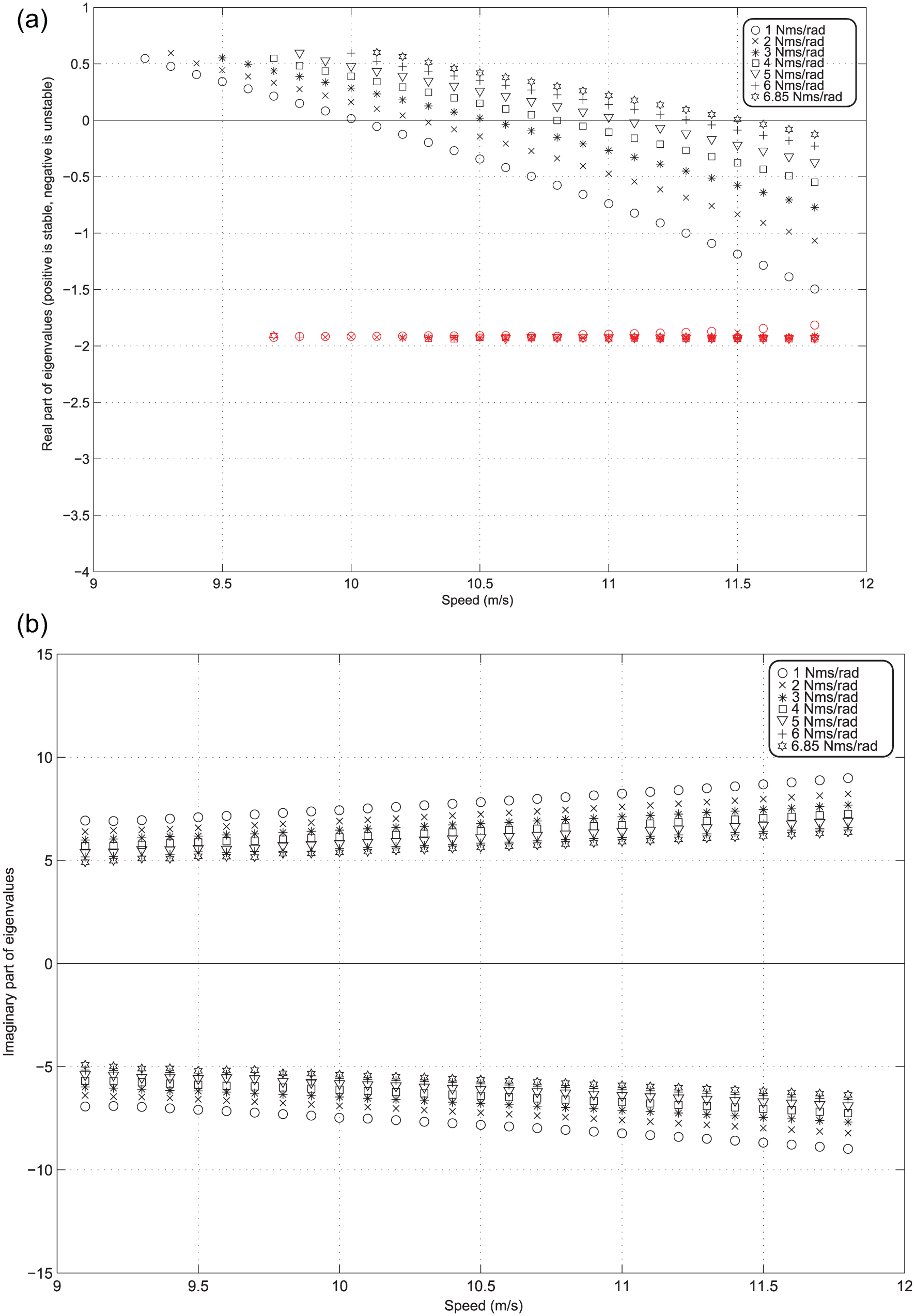
Effect of arm damping on the weave mode: (a) real parts and (b) imaginary parts.
Discussion
The good match of the results of the multibody dynamic simulation in ADAMS with the benchmark model results points out that the time domain simulations and the system identification method are valid. A limitation of this method is that it negates the possibility of calculating the eigenvalues over the full speed range. An unstable weave or capsize mode results in a simulation time that is too short to enable fitting of the signals in the time domain. Therefore, only the identified model that fits the time domain signals well is shown.
Destabilization of the weave mode and stabilization of the capsize mode by implementing the realistic tyre model can be mainly attributed to the twisting torque. Sharp 6 showed some effect of a linear tyre model on the stability of a bicycle. Notable is that he did not incorporate the twisting torque into the tyre model. In return, Plöchl et al. 10 and Klinger et al. 13 did include the twisting torque and found a significant effect of their tyre model on the capsize and weave mode. In agreement with the results presented in this article, they found that the capsize mode becomes stable and the weave mode significantly destabilizes by implementing the realistic tyre model. The sensitivity study of tyre parameters again confirms that the twisting torque is the main contributor. The twisting torque does not align the wheel, but it tends to move the cambered wheel along a trajectory with a decreasing curvature, due to a negative longitudinal slip at the inside of the contact patch and a positive longitudinal slip at the outside of the contact patch. 26 Together with the self-aligning torque (that works in opposite direction and tends to align the wheel), it represents the yaw torque (for each wheel). If the twisting torque coefficient (DTT ) is high, the yaw torque is already positive for low sideslip and camber angles. As the weave stability is closely related to the steer-in-the-fall-mechanism, 8 the shift of the stable weave speed to higher forward speeds for an increased twisting torque can be explained by the high positive value of the yaw torque that steers the bicycle into the fall too much. Furthermore, it was found that already a small twisting torque ensures a stable capsize mode. The capsize mode is usually a very slow motion and therefore easy to control for the rider. However, it determines the sign of the steering torque; at the capsize speed, no extra steering torque is necessary for a steady forward motion (straight or during a steady turn).
The large influence of the twisting torque on stability was also found for motorcycle models. 15 It is worth highlighting that the influence is large especially at low speeds, which are the most important for bicycles.
In addition to the twisting torque, the camber stiffness has a large influence on the weave stability. Plöchl et al. 10 reported this as well. Cossalter et al. 28 reported a high influence of the cornering stiffness for high speeds of racing motorcycles. These findings cannot be extrapolated to low-speed behaviour of the bicycle. They also found that different tyres and inflation pressure cause a large change in stability of a sport-touring motorcycle.29,30 For example, using different tyres may cause a change in weave damping ratio of 47%. 28 Similarly, Evangelou 29 reported that the effect of tyre inflation pressure is high for high speeds of motorcycles. Contradictory, our study shows a small effect of different tyres and inflation pressures on the bicycle stability. This fact can be explained considering the different properties of bicycle tyres and the different ranges of the variation in inflation pressure.
The effect of the vertical load on the tyre properties is more prominent; when using the tyre properties based on measurements with a higher nominal load, the weave mode stabilizes. This can be explained by the decrease in normalized twisting torque when increasing load, presented in Doria et al. 18 This indicates that the load-dependent tyre properties are important and should be taken into account in dynamic bicycle models. Scaling factors are obtained from a small data set 18 and presented in Appendix 1 of this article.
Finally, it may be stated that tyre properties change the dynamics of the bicycle to a large extent and that they should be taken into account in future dynamic bicycle models. Moore 31 performed the experiments to identify the Whipple model and found some deficiencies that might be attributed to the simplified tyre–road contact model. To verify this, more validation of dynamic bicycle models is needed.
Adding the passive joint properties of the bicycle’s rider does not significantly change the dynamic properties, compared to the rigid rider model. This is in accordance with previous studies.6,12 However, modelling the rider’s arms on the steer does drastically change the dynamic properties.12,13 In Doria and Tognazzo, 12 it was reported that a small amount (25.7 N m/rad) of passive arm stiffness is able to destroy the stability by making the steer–roll combination ineffective. However, in Doria and Tognazzo, 12 tyre dynamics were not considered and this significantly changes the influence of the rider’s impedance on the handlebars. The tyre model creates the opposite effect of the addition of arm stiffness and stabilizes the capsize mode for high speeds. This might be caused by the twisting torque that generates a yaw torque in the direction of the fall. In Klinger et al., 13 the tyre dynamics were considered, but a very small value of passive arm stiffness (3.2 N m/rad) was used in their basic hands-on model, and therefore they did not find an unstable capsize mode.
Combining passive arm damping with the new tyre model does not change the influence on the bicycle stability, compared to the addition of passive arm damping alone. In both cases, a clear tendency of a decreased weave stability is seen. The capsize mode remains always stable, when the tyre model is used together with passive arm damping.
Conclusion
In this article, a new parameterized passive bicycle-rider model developed in the commercially available software package ADAMS is presented. This is a first step in the development of an advanced dynamic model to simulate problem scenarios of elderly cyclists. Several improvements of previous models are combined into one model: the addition of passive rider properties and tyre dynamics. The simulations with this model showed that a realistic tyre model has a high influence on the stability of the system: the weave mode destabilizes and the capsize mode is always stable.
A sensitivity analysis on the influence of tyre properties on the weave speed showed that the twisting torque is the main contributor to the destabilization, followed by the camber stiffness. Tyre inflation pressure has a small influence on the weave mode, in contrast to what was found for motorcycle tyres. The tyre properties are highly load-dependent, and therefore bicycle tyre models need to include load-dependent coefficients.
Extending the benchmark bicycle model with passive rider properties does not change the dynamics of the bicycle-rider system a lot when riding at a constant forward speed. Passive arm stiffness and damping, however, drastically change the dynamics: passive arm stiffness destabilizes the capsize mode. The tyre model can, however, counteract this capsize instability.
Footnotes
Appendix 1
Academic Editor: Anand Thite
Declaration of Conflicting Interests
The author(s) declared no potential conflicts of interest with respect to the research, authorship, and/or publication of this article.
Funding
The author(s) disclosed receipt of the following financial support for the research, authorship, and/or publication of this article: This study was supported by a grant from the RVO NL.
References
Supplementary Material
Please find the following supplemental material available below.
For Open Access articles published under a Creative Commons License, all supplemental material carries the same license as the article it is associated with.
For non-Open Access articles published, all supplemental material carries a non-exclusive license, and permission requests for re-use of supplemental material or any part of supplemental material shall be sent directly to the copyright owner as specified in the copyright notice associated with the article.